【0001】
【産業上の利用分野】
本発明は、樹脂製自動車用衝撃緩衝部材に係り、バンパー、バンパービーム等に利用できる。
【0002】
【背景技術】
従来より、バンパー、バンパービーム等の自動車用衝撃緩衝部材には、金属製のものが多用されてきた。この金属製のバンパー等は、強度的には問題ないが、重量が大きい、腐食しやすいなどの欠点があった。このため、近年では、省資源の要請や軽量化の観点から、プラスチック製のバンパー等が採用されるようになってきた。
【0003】
このようなプラスチック製のバンパー等は、通常、射出成形により製造されている。しかし、射出成形による製造では、バンパー等が比較的大型の成形品であることから成形機が大型になるという問題、あるいは高い射出成形圧が必要であることから金型が高価になるという問題があった。さらに、射出成形による製造では、金型のキャビティ形状を変更することで成形品の外形形状については比較的自由に設計できるものの、衝撃緩衝を効果的に行うことができる中空構造を有するバンパー等の製造は困難であった。
【0004】
これに対し、衝撃緩衝を効果的に行うために、ブロー成形により製造される中空構造を有する各種の自動車用衝撃緩衝部材が提案されている(特開平4−120145号公報等参照)。
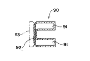
図18には、このような中空構造を有する自動車用衝撃緩衝部材の一例であるバンパービーム90の長手方向直交断面が示されている。バンパービーム90は、このような断面形状が長手方向に連続して形成されている。
このようなバンパービーム90によれば、中空部分91を有しているので、この中空部分91で衝撃を緩衝することができる。
【0005】
【発明が解決しようとする課題】
しかしながら、前述したブロー成形により製造される中空構造を有する自動車用衝撃緩衝部材では、成形方法の特殊性から、その構造や形状は例えば図18に示すように比較的単純なものが多かった。
近年、自動車用のバンパー等は、軽量化の強い要求があることに加え、安全対策上の要求が益々多様化するとともに厳しくなっているため、従来の比較的単純な構造や形状のものでは、これらの要求の全てに充分に対応することが困難となってきており、より一層軽量化を図ることができるとともに実際の衝突を想定した各種の試験に合格することができる自動車用衝撃緩衝部材が望まれていた。
【0006】
また、5MPHペンデュラム試験、バリヤ試験、ポール試験等の規格試験や一般試験に合格させるために、例えば、図18のバンパービーム90の前面部92の前方位置に図中二点鎖線のように発泡体等のエネルギー吸収用の部品93を入れたバンパーとする、あるいはバンパービーム90の肉厚を厚くする等の対策が考えられるが、これらの対策では、高価格となる、あるいは重量が増加する等の問題が発生する。このため、前述した要求の全てには対応できない。
【0007】
本発明の目的は、充分な衝撃緩衝機能を備えるとともに衝撃時の変形量が少なく、かつ軽量な樹脂製自動車用衝撃緩衝部材を提供することにある。
【0008】
【課題を解決するための手段】
本発明は、長尺部材の表面部を特殊な構造として前記目的を達成しようとするものである。具体的には、本発明の樹脂製自動車用衝撃緩衝部材は、中空部を有する長尺部材により形成され、この長尺部材の表面部には長手方向に沿って複数の凹部が、当該表面部の前面部から上面部、及び前面部から下面部に跨って千鳥状に配置形成されていることを特徴とする。ここで、表面部とは、自動車本体への取付側の部分(裏面部)を除く部分のことであり、自動車前面側の部分と上面および下面部分とを含むものである。但し、前面側とは自動車の進行方向を意味するものではなく、樹脂製自動車用衝撃緩衝部材がフロントではなくリヤに取り付けられる場合には、進行方向と逆向きの面となる。
【0009】
また、複数の凹部のうちの少なくとも一つは、長尺部材の長手方向に沿った中心線を越えて配置形成されていることが強度上の点で望ましい。ここで、「中心線を越えて配置形成」とは、中心線を跨ぐように配置形成することである。
そして、複数の凹部のうちの少なくとも一つは、長尺部材の裏面部に結合されていることが強度上の点で望ましく、特に全ての凹部が裏面部に結合されていることが好ましい。
さらに、長尺部材の裏面部にリブを形成する、あるいは長尺部材の裏面部に補強用芯材をインサートすることにより、より一層強度を向上させてもよい。
【0010】
また、以上に述べた本発明の樹脂製自動車用衝撃緩衝部材の成形方法は、ブロー成形が好適であるが、所望の形状を得ることができれば、例えば、ガス射出成形法(中空射出成形法)などの他の成形方法であってもよい。
ここで、ブロー成形に用いる材料としては、従来よりバンパー等の樹脂製自動車用衝撃緩衝部材の材料として用いられている熱可塑性樹脂の中から任意に選ぶことができる。
例えば、ポリプロピレン、高密度ポリエチレン、線状低密度ポリエチレン、ポリ塩化ビニル、ポリカーボネート、ポリアミド、ポリエチレンテレフタレート、ポリスチレン、ポリオキシメチレン、ABS樹脂、AS樹脂、ポリフェニレンエーテル、ポリフェニレンスルフィドなどの熱可塑性樹脂、およびこれらの樹脂にエチレン・プロピレンゴム、エチレン・プロピレン・ジエン三次元ゴムなどのゴム類および/または充填剤としてガラス繊維、炭素繊維、タルク、マイカ、炭酸カルシウムなどを配合したものを挙げることができる。なお、これらの樹脂、ゴム類、充填剤などは、必要に応じて複数のものを配合するようにしてもよい。
【0011】
しかし、本発明のような特定形状を有する樹脂製自動車用衝撃緩衝部材をブロー成形するための材料として、成形加工性、成形品の物性、耐衝撃性、ピンチオフ強度などの機械的強度の点で、特に好適な材料は、メルトインデックス〔230℃、2.16kgf〕が2.0g/10分以下、アイソタクチックペンタッド分率93モル%以上のプロピレン単独重合体、またはメルトインデックスが2.0g/10分以下、エチレン単位含有量15重量%以下、プロピレンホモ重合部のアイソタクチックペンタッド分率93モル%以上のプロピレンブロック共重合体、あるいはこれらのプロピレン系重合体と高密度ポリエチレン、エチレン・プロピレン系エラストマー、エチレン・α−オレフィン(プロピレン以外)系エラストマー、エチレン・プロピレン・ジエン系エラストマーなどのエラストマー、タルクなどの充填剤の中から選択された一種以上のものとの組成物である。
ここで、プロピレン系重合体60〜99重量%、高密度ポリエチレン0〜30重量%、エチレン・α−オレフィン系エラストマー0〜20重量%、タルクなどの充填剤0〜40重量%の範囲において用いられる。
また、この組成物には、さらに所望に応じ、無水マレイン酸変性ポリオレフィン、アクリル酸変性ポリオレフィンのような極性基含有熱可塑性樹脂、炭酸カルシウム、マイカ、ガラス繊維、炭素繊維のような無機充填剤、あるいは酸化防止剤、紫外線吸収剤、熱安定剤、滑剤、難燃剤、着色剤などの各種添加剤を含有することができる。
【0012】
【作用】
このような本発明においては、千鳥状に配置された複数の凹部により衝撃時のエネルギーが吸収される。この際、複数の凹部の側壁(特に、樹脂製自動車用衝撃緩衝部材の長手方向に直交する方向に延びる側壁)が、リブの役割を果たすため、一定の強度を確保しながら所望の衝撃緩衝機能が得られる。また、長尺部材としては、特に限定されるものではないが、少なくとも両端部分に湾曲部を有することが好ましく、このような湾曲形状とすることによって衝撃力を長尺部材全体で受けやすくなるため、より優れた衝撃緩衝機能が得られる。このため、従来のような中空部のみにより衝撃緩衝を行う場合に比べ、多様な衝撃条件を満足できる優れた衝撃緩衝機能が得られる。
また、衝撃緩衝機能を向上させるにあたって、エネルギー吸収用の部品を別途設けたり、あるいは部材の肉厚を厚くする必要はないので、コスト低減、軽量化が図られ、これらにより前記目的が達成される。
【0013】
また、複数の凹部のうちの少なくとも一つ、好ましくは全部を、長尺部材の長手方向に沿った中心線を越えるように配置形成した場合には、リブの役割を果たす側壁が適切な長さ確保されるため、より一層優れた衝撃緩衝機能が得られる。さらに、複数の凹部のうちの少なくとも一つ、好ましくは全部を、長尺部材の裏面部に結合させれば、強度の向上が図られる。そして、前述したように凹部を中心線を越えるように配置形成した場合には、凹部と裏面部との結合が容易に実現される。
また、長尺部材の裏面部にリブを形成したり、あるいは長尺部材の裏面部に補強用芯材をインサートすれば、より一層強度の向上が図られる。
【0014】
【実施例】
以下、本発明の各実施例を図面に基づいて説明する。
〔第一実施例〕
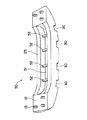
図1には、本発明の第一実施例の樹脂製自動車用衝撃緩衝部材であるバンパービーム10の斜視図が示され、図2、図3には、それぞれバンパービーム10の前面図、上面図(図2中矢印Z方向から見た図)が示されている。また、図4、図5、図6には、それぞれ図2中のA−A線、B−B線、C−C線に沿ったバンパービーム10の長手方向直交断面が示されている。
バンパービーム10は、ブロー成形による成形品であり、図1〜図3に示す如く、図中左右方向に延びかつ両端部分に湾曲部を有する長尺部材11により形成されている。
長尺部材11の長手方向両端部の裏面側(図3中下側)には、図示されない自動車本体への取付用の取付面12が形成されている。この取付面12には、適宜な本数の埋込みボルト13が設けられている。
【0015】
長尺部材11の内部には、図4〜図6に示す如く、中空部20が長尺部材11の長手方向の全体に渡って形成されている。
長尺部材11の表面部21(前面部22、上面部23、および下面部24)には、長尺部材11の長手方向に沿って複数の凹部30が千鳥状に配置形成されている。
つまり、前面部22と上面部23との角部(図2中上側位置)に四つの凹部30が配置形成され、一方、前面部22と下面部24との角部(図2中下側位置)に三つの凹部30が配置形成され、これらの凹部30は、上面部23側、下面部24側に交互に配置されている。
【0016】
各凹部30は、前面部22側から見た状態で略矩形形状に形成されるとともに、前面部22の上下の端縁位置から長尺部材11の長手方向の中心線(図2中の一点鎖線K)を越える位置まで形成されている。
また、各凹部30が中心線Kを越える分の寸法Sは、0〜50mm程度が好ましく、より好ましくは10〜30mm程度である。
【0017】
さらに、各凹部30の長手方向の幅W(図2参照)は、後述する試験用ポールの直径(7inch=178mm)よりも小さくなっており、好ましくは50〜150mm程度がよく、より好ましくは80〜130mm程度である。
そして、各凹部30の深さL1(図4参照)は、バンパービーム10の前面部22の平坦な部分から裏面部25の平坦な部分までの幅Lに対して、L1=1/5L〜1/2L程度が好ましく、より好ましくはL1=1/4L〜1/3L程度である。なお、幅Lの寸法は、バンパービーム10が取り付けられる自動車本体の種類(大きさ、重量等)に応じて決定される。
【0018】
長尺部材11の裏面部25(自動車本体への取付側)には、前面部22側に突出する突出部26が形成され、この突出部26の先端26Aは、各凹部30に結合されている。
また、突出部26の内部には、図4〜図6に示す如く、中空の補強用芯材40がインサートされている。補強用芯材40は、長尺部材11の長手方向の略全長に渡って設けられ、図3中の一点鎖線に示すように、取付面12の位置まで配置されている。しかし、必ずしも取付面12の位置まで配置されていなくてもよい。なお、本発明においてインサートされる補強用芯材の形状は、このような形状に限定されるものではなく任意である。
【0019】
この補強用芯材40の材質は、特に限定されるものではないが、例えば、特開平5−239286号で提案されているものに準じた次のようなものを用いることができる。
(A)メルトインデックス300g/10分以上のプロピレン単独重合体又はプロピレン−エチレン共重合体20〜60重量%とガラス繊維80〜40重量%とから成り、ペレット長が2〜20mmで、かつ、該ガラス繊維長がペレット長に実質上等しいペレット5〜70重量部と、(B)メルトインデックスが3〜20g/10分でアイソタクチックペンタッド分率が93モル%以上のプロピレン単独重合体又はプロピレン−エチレン共重合体95〜30重量部とを全量が100重量部になるように混合したガラス繊維強化ポリオレフィン樹脂組成物、あるいは、(A’)メルトインデックス300g/10分以上のプロピレン単独重合体又はプロピレン−エチレン共重合体20〜60重量%とガラス繊維80〜40重量%とから成る混合物100重量部に対し、酸付加量0.1〜10重量%の酸変性ポリオレフィン1〜10重量部を配合して成り、ペレット長が2〜20mmで、かつ、該ガラス繊維長がペレット長に実質上等しいペレット5〜70重量部と、(B)メルトインデックスが3〜20g/10分で、アイソタクチックペンタッド分率が93モル%以上のプロピレン単独重合体又はプロピレン−エチレン共重合体95〜30重量部とを全量が100重量部になるように混合したガラス繊維強化ポリオレフィン樹脂組成物などである。
なお、補強用芯材としては、このようなガラス繊維強化ポリオレフィン樹脂組成物の他に、樹脂のみで形成されたもの、充填剤配合樹脂組成物、あるいは繊維強化熱硬化性樹脂(GFRP)、金属などで形成されたものを用いてもよい。
【0020】
このような第一実施例においては、以下のようにしてブロー成形によりバンパービーム10を製造する。
先ず、バンパービーム10の外形形状に従ったキャビティを有する成形用金型(不図示)を用意する。この成形用金型には、各凹部30に対応した表面形状のキャビティが形成されている。
次に、成形用金型のキャビティの内部に予め成形しておいた補強用芯材40を取り付ける。
その後、成形用金型により筒状のパリソンを外側から挟み込むとともに、パリソンの内側の空洞部分に空気を吹き込んでパリソンを拡げて成形用金型のキャビティ表面および補強用芯材40の周囲に密着させる。
そして、成形用金型を開き、完成したバンパービーム10を取り出す。この際、補強用芯材40もバンパービーム10として一体化されて取り出される。
【0021】
このような第一実施例によれば、次のような効果がある。
すなわち、バンパービーム10の表面部21には、千鳥状に配置された複数の凹部30が設けられているので、この複数の凹部30が形成された部分(ハニカム構造部分)により衝撃時のエネルギーを吸収できる。
そして、複数の凹部30の側壁(特に、バンパービーム10の長手方向に直交する方向に延びる側壁31)が、リブの役割を果たすため、一定の強度を確保しながら所望の衝撃緩衝機能を得ることができる。
このため、従来のような中空部のみにより衝撃緩衝を行う場合に比べ、多様な衝撃条件を満足できる優れた衝撃緩衝機能を得ることができる。
【0022】
また、衝撃緩衝機能を向上させるにあたって、エネルギー吸収用の部品(例えば、図18の部品93)を別途設けたり、あるいは部材の肉厚を厚くする必要はないので、コスト低減、軽量化を図ることができる。
【0023】
さらに、複数の凹部30は、千鳥状の配置となっているので、側壁31は、適宜な間隔でかつ上下両側に略均等に配置されるため、バンパービーム10の全体に渡って優れた衝撃緩衝機能を得ることができる。
そして、各凹部30は、長手方向に沿った中心線K(図2参照)を越える位置まで形成されているので、適切な長さの側壁31を確保することができ、より一層優れた衝撃緩衝機能を得ることができる。
【0024】
また、各凹部30の長手方向の幅W(図2参照)、つまり凹部30の対向する側壁31間の間隔は、後述する試験用ポールの直径よりも小さくなっているので、ポールに衝突した時のような局部的な衝撃に対しても優れた衝撃緩衝機能を発揮することができる。
【0025】
さらに、各凹部30は、裏面部25の一部である突出部26の先端26Aに結合されているので、バンパービーム10の強度の向上を図ることができる。そして、各凹部30が中心線Kを越えるように配置形成されていることから、このような各凹部30と突出部26の先端26Aとの結合を容易に実現することができる。
【0026】
また、突出部26の内部には、例えば繊維複合材等からなる補強用芯材40がインサートされているので、バンパービーム10の強度のより一層の向上を図ることができる。
【0027】
〔第二実施例〕
図7〜図9には、本発明の第二実施例の樹脂製自動車用衝撃緩衝部材であるバンパービーム50が示されている。図7には、バンパービーム50の上面図が示され、図8には、バンパービーム50を裏面側から見た斜視図が示され、図9には、図7中のD−D線に沿ったバンパービーム50の長手方向直交断面が示されている。
バンパービーム50は、前記第一実施例のバンパービーム10と略同様な構成を有し、裏面部25の構成が一部異なるのみであるので、同一部分には同一符号を付して詳しい説明は省略し、以下には異なる部分のみを説明する。
【0028】
前記第一実施例のバンパービーム10では、突出部26の内部に補強用芯材40がインサートされていたが、本第二実施例のバンパービーム50では、突出部51の内部に補強用芯材40はインサートされていない。また、本第二実施例の突出部51は、前記第一実施例の突出部26とは異なり、取付面12の位置まで形成されていない。
突出部51の内部には、バンパービーム50の長手方向に直交する方向に延びる四本のリブ52が適宜な間隔で設けられている。
【0029】
このような第二実施例によれば、前記第一実施例の補強用芯材40の代わりにリブ52が設けられているので、前記第一実施例と同様に、優れた衝撃緩衝機能および強度を得ることができるという効果がある。
【0030】
〔比較実験〕
なお、本発明の効果を確かめるために、以下のような5MPHペンデュラム試験、5MPHバリヤ試験、5MPHポール試験による比較実験を行った。
本発明の実験例として、前記第一実施例のバンパービーム10において補強用芯材40が設けられていない場合(実験例1)、前記第二実施例のリブ52を有するバンパービーム50の場合(実験例2)、前記第一実施例の補強用芯材40を有するバンパービーム10の場合(実験例3)を用意した。
一方、比較例として、前述した図18の断面形状を有するバンパービーム90の場合(比較例1)、図19の断面形状に示すような前面側の上下に突起部95を有するバンパービーム96の場合(比較例2)を用意した。
【0031】
そして、各実験例1〜3および各比較例1,2のパンパービームの原料樹脂には、
(1)メルトインデックス1g/10分のポリプロピレン(出光石油化学株式会社製、E250G)65重量%と、
(2)メルトインデックス0.03g/10分の高密度ポリエチレン(出光石油化学株式会社製、750LB)20重量%と、
(3)ムーニー粘度〔ML1+4 (100℃)〕=77、エチレン含量73重量%のエチレン・プロピレンエラストマー(日本合成ゴム株式会社製、EP07P)5重量%と、
(4)平均粒径1.5μm、平均アスペクト比15のタルク10重量%と、
を含む樹脂組成物を用いた。
【0032】
また、成形条件および温度条件は、次の通りである。
〔成形条件〕
成形機 :90mmφ
ダイ :100mmφ
アキュームレータ :25リットル
型締圧力 :60ton
スクリュー回転数 :40rpm
モーター負荷 :115A
【0033】
【0034】
このようにして成形された各実験例1〜3および各比較例1,2のバンパービームを被試験体とし、製品重量4.5kg、製品長さ1.4m、車両重量1200kg、常温にて5MPH(衝撃速度8km/Hr=5mile/Hr)のペンデュラム試験(上下打ち、35mm)、バリヤ試験、ポール試験(直径7inch)の各規格試験を行い、各実験例1〜3および各比較例1,2について、それぞれ最大変形量、最大発生荷重、すべりの有無を調べて総合評価を行った。
この比較実験の結果を次の表1〜表3および図10〜図12に示す。表1、表2、表3には、それぞれペンデュラム試験、バリヤ試験、ポール試験の結果が示されている。また、図10、図11、図12には、それぞれペンデュラム試験、バリヤ試験、ポール試験における変形量と発生荷重との関係が示されている。
【0035】
【表1】
【0036】
【表2】
【0037】
【表3】
【0038】
表1〜表3によれば、各実験例1〜3では、全ての試験において最大変形量が小さく、かつ最大発生荷重が大きく、総合評価も良好となっているのに対し、各比較例1,2では、比較例2のペンデュラム試験において総合評価が良好となっていることを除き、総合評価は悪い結果となっている。また、比較例2についても他のバリヤ試験、ポール試験においては総合評価は悪い結果となっているので、不充分な性能であるといえる。
【0039】
また、図10によれば、図中点線で示された比較例1では、ペンデュラムリーデが滑って変形量が大きいのに対し、図中一点鎖線で示された比較例2では、図19中の突起部95が潰れることにより、すべりが防止され、図中実線で示された実験例1では、複数の凹部30が形成された部分(ハニカム構造部分)が一部エネルギーを吸収して変形し、すべりが防止されていることがわかる。
さらに、図11によれば、図中点線で示された比較例1では、バンパービーム全体が一気に荷重を受けてバンパービームの欠陥部が座屈し、発生荷重が小さくかつ変形量が大きくなるのに対し、図中実線で示された実験例1では、複数の凹部30が形成された部分(ハニカム構造部分)で徐々に荷重が立ち上がって均一な応力が全体にかかっていき、最終的に発生荷重が大きくかつ変形量が小さくなることがわかる。
【0040】
そして、図12によれば、図中点線で示された比較例1では、局部的に応力が集中して早期に座屈が起こり、発生荷重が小さくかつ変形量が大きくなるのに対し、図中実線で示された実験例1では、複数の凹部30が形成された部分(ハニカム構造部分)により応力を広い範囲で受け、発生荷重が大きくかつ変形量が小さくなることがわかる。
以上の比較実験結果により、本発明によるバンパービームが優れた衝撃緩衝機能および強度を備え、各種の試験に充分に対応できることが示され、本発明の効果が顕著に示された。
【0041】
なお、本発明は前記各実施例に限定されるものではなく、本発明の目的を達成できる他の構成も含み、例えば以下に示すような変形等も本発明に含まれるものである。
すなわち、前記第一、第二実施例では、各突起部26,51の内部に、それぞれ補強用芯材40、リブ52が設けられていたが、突起部の内部に補強用芯材およびリブの両方が設けられていてもよい。
また、これらの補強用芯材40やリブ52は必ずしも必要なものではなく、その用途によっては省略してもよいが、強度上の点で設けておくことが好ましい。さらに、本発明の樹脂製自動車用衝撃緩衝部材の裏面部に形成されるリブは、前記第二実施例のような形状のリブ52に限定されるものではなく、例えば、図13に示すような形状のリブ60としてもよい。
【0042】
また、前記各実施例では、合計7個の凹部30が設けられていたが、複数の凹部30が千鳥状に配置されていれば、凹部30の個数は任意であってよい。
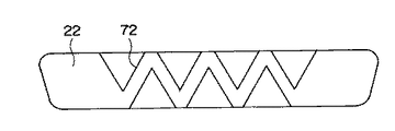
さらに、前記各実施例では、各凹部30の形状は、前面部22側から見て略矩形形状となっていたが、凹部の形状は任意であり、例えば、図14に示すように略台形形状の凹部71としてもよく、図15に示すように略三角形形状の凹部72としてもよく、あるいは図16に示すように略半円形形状の凹部73としてもよく、要するに複数の凹部が千鳥状に配置されていればよい。
【0043】
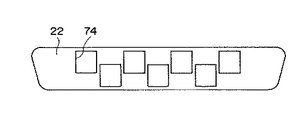
そして、前記各実施例では、各凹部30は、前面部22から上面部23または下面部24に跨がって形成されていたが、図17に示すように前面部22のみに形成された凹部74としてもよい。
【0044】
【発明の効果】
以上に述べたように本発明によれば、千鳥状に配置された複数の凹部により衝撃時のエネルギーを吸収できるとともに、各凹部の側壁がリブの役割を果たすため、多様な衝撃条件を満足できる優れた衝撃緩衝機能および強度を得ることができるうえ、部材の肉厚を厚くする必要はないので、軽量化およびコスト低減を図ることができるという効果がある。
【0045】
また、複数の凹部のうちの少なくとも一つを、長尺部材の長手方向に沿った中心線を越えるように配置形成した場合には、リブの役割を果たす側壁を適切な長さ確保できるため、より一層優れた衝撃緩衝機能を得ることができるという効果がある。
そして、長尺部材の少なくとも両端部分を湾曲形状としておけば、衝撃力の分散を図ることができるという効果がある。
さらに、複数の凹部のうちの少なくとも一つを、長尺部材の裏面部に結合させた場合には、強度の向上をより一層図ることができるという効果がある。
【0046】
また、長尺部材の裏面部にリブを形成した場合、あるいは長尺部材の裏面部に繊維複合材等からなる補強用芯材をインサートした場合には、これらによっても強度の向上をより一層図ることができるという効果がある。
【図面の簡単な説明】
【図1】本発明の第一実施例のバンパービームの斜視図。
【図2】第一実施例のバンパービームの前面図。
【図3】第一実施例のバンパービームの上面図。
【図4】第一実施例のバンパービームの図2中A−A線に沿った断面図。
【図5】第一実施例のバンパービームの図2中B−B線に沿った断面図。
【図6】第一実施例のバンパービームの図2中C−C線に沿った断面図。
【図7】本発明の第二実施例のバンパービームの上面図。
【図8】第二実施例のバンパービームの裏面側から見た斜視図。
【図9】第二実施例のバンパービームの図7中D−D線に沿った断面図。
【図10】比較実験(ペンデュラム試験)の結果図。
【図11】比較実験(バリヤ試験)の結果図。
【図12】比較実験(ポール試験)の結果図。
【図13】本発明の第一の変形例を示す裏面図。
【図14】本発明の第二の変形例を示す前面図。
【図15】本発明の第三の変形例を示す前面図。
【図16】本発明の第四の変形例を示す前面図。
【図17】本発明の第五の変形例を示す前面図。
【図18】従来例(比較例1)を示す断面図。
【図19】比較例2を示す断面図。
【符号の説明】
10,50 樹脂製自動車用衝撃緩衝部材であるバンパービーム
11 長尺部材
20 中空部
21 表面部
22 表面部を構成する前面部
23 表面部を構成する上面部
24 表面部を構成する下面部
25 裏面部
26,51 裏面部を構成する突出部
30,71,72,73,74 凹部
40 補強用芯材
52,60 リブ
K 中心線[0001]
[Industrial applications]
INDUSTRIAL APPLICABILITY The present invention relates to a resin shock absorber for automobiles, and can be used for bumpers, bumper beams, and the like.
[0002]
[Background Art]
BACKGROUND ART Conventionally, metal shock absorbing members such as bumpers and bumper beams have often been made of metal. Although this metal bumper or the like has no problem in strength, it has disadvantages such as heavy weight and easy corrosion. For this reason, in recent years, plastic bumpers and the like have come to be used from the viewpoint of resource saving and weight reduction.
[0003]
Such a plastic bumper or the like is usually manufactured by injection molding. However, in manufacturing by injection molding, there is a problem that a molding machine becomes large because a bumper or the like is a relatively large molded product, or a problem that a mold is expensive because a high injection molding pressure is required. there were. In addition, in the production by injection molding, although the external shape of the molded product can be designed relatively freely by changing the cavity shape of the mold, a bumper or the like having a hollow structure capable of effectively cushioning impacts can be designed. Manufacturing was difficult.
[0004]
On the other hand, in order to effectively absorb shock, various kinds of shock absorbing members for automobiles having a hollow structure manufactured by blow molding have been proposed (see JP-A-4-120145).
FIG. 18 shows a cross section orthogonal to the longitudinal direction of a bumper beam 90 which is an example of an automobile shock absorbing member having such a hollow structure. In the bumper beam 90, such a cross-sectional shape is formed continuously in the longitudinal direction.
According to such a bumper beam 90, since the hollow portion 91 is provided, the hollow portion 91 can buffer an impact.
[0005]
[Problems to be solved by the invention]
However, in the case of the impact cushioning member for automobiles having a hollow structure manufactured by the blow molding described above, the structure and shape are often relatively simple as shown in FIG. 18, for example, due to the specificity of the molding method.
In recent years, in addition to the strong demands for lighter weight, the demands for safety measures have become more diversified and stricter in recent years. It has become difficult to sufficiently satisfy all of these requirements, and an automobile impact cushioning member that can achieve further weight reduction and can pass various tests assuming an actual collision has been developed. Was desired.
[0006]
In order to pass a standard test such as a 5MPH pendulum test, a barrier test, and a pole test, and a general test, for example, a foamed material as shown by a two-dot chain line in FIG. And the like, or to increase the thickness of the bumper beam 90. However, these measures increase the cost or increase the weight. Problems arise. For this reason, all of the above-mentioned requests cannot be met.
[0007]
SUMMARY OF THE INVENTION An object of the present invention is to provide a light-weight resin shock absorbing member for a vehicle, which has a sufficient shock absorbing function and has a small deformation amount upon impact.
[0008]
[Means for Solving the Problems]
The present invention is intended to achieve the above-mentioned object by making the surface of the long member a special structure. Specifically, the resin-made automobile shock-absorbing member of the present invention is formed by a long member having a hollow portion, and a plurality of recesses are formed on the surface of the long member along the longitudinal direction. From the front part to the upper part and from the front part to the lower part of the surface part It is characterized by being arranged in a staggered manner. Here, the front surface portion is a portion excluding a portion on the side of attachment to the vehicle body (back surface portion), and includes a front portion of the vehicle, and upper and lower surfaces. However, the front side does not mean the traveling direction of the vehicle, and when the resin-made vehicle shock-absorbing member is attached to the rear rather than the front, the surface is opposite to the traveling direction.
[0009]
In addition, it is desirable that at least one of the plurality of recesses is formed so as to extend beyond a center line along the longitudinal direction of the long member, from the viewpoint of strength. Here, “arrangement and formation beyond the center line” means to arrange and form so as to straddle the center line.
At least one of the plurality of recesses is desirably coupled to the back surface of the long member from the viewpoint of strength, and it is particularly preferable that all recesses are coupled to the back surface.
Further, the strength may be further improved by forming a rib on the back surface of the long member or inserting a reinforcing core material on the back surface of the long member.
[0010]
In the above-described method of molding the resin shock absorbing member for a vehicle according to the present invention, blow molding is suitable, but if a desired shape can be obtained, for example, gas injection molding (hollow injection molding) Other molding methods may be used.
Here, the material used for blow molding can be arbitrarily selected from thermoplastic resins conventionally used as materials for resin shock absorbing members made of resin such as bumpers.
For example, thermoplastic resins such as polypropylene, high-density polyethylene, linear low-density polyethylene, polyvinyl chloride, polycarbonate, polyamide, polyethylene terephthalate, polystyrene, polyoxymethylene, ABS resin, AS resin, polyphenylene ether, polyphenylene sulfide, and the like. And the like, and rubbers such as ethylene-propylene rubber and ethylene-propylene-diene three-dimensional rubber and / or glass fiber, carbon fiber, talc, mica, calcium carbonate and the like as fillers. In addition, you may make it mix these resin, rubber | gum, a filler, etc. as needed.
[0011]
However, as a material for blow molding a resin-made automobile shock absorbing member having a specific shape as in the present invention, in terms of moldability, physical properties of a molded article, impact resistance, and mechanical strength such as pinch-off strength. Particularly preferred materials are a propylene homopolymer having a melt index [230 ° C., 2.16 kgf] of 2.0 g / 10 min or less, an isotactic pentad fraction of 93 mol% or more, or a melt index of 2.0 g. / 10 minutes or less, ethylene unit content of 15% by weight or less, propylene block copolymer having an isotactic pentad fraction of 93 mol% or more of propylene homopolymerized section, or these propylene-based polymers and high-density polyethylene, ethylene・ Propylene elastomer, ethylene / α-olefin (other than propylene) elastomer, ethylene Elastomers such as propylene-diene-based elastomer is a composition of one or more of those selected from among fillers such as talc.
Here, the propylene polymer is used in the range of 60 to 99% by weight, high density polyethylene 0 to 30% by weight, ethylene / α-olefin elastomer 0 to 20% by weight, and filler such as talc 0 to 40% by weight. .
Further, the composition furthermore, if desired, a maleic anhydride-modified polyolefin, a polar group-containing thermoplastic resin such as an acrylic acid-modified polyolefin, calcium carbonate, mica, glass fiber, inorganic fillers such as carbon fiber, Alternatively, various additives such as an antioxidant, an ultraviolet absorber, a heat stabilizer, a lubricant, a flame retardant, and a coloring agent can be contained.
[0012]
[Action]
In the present invention, the energy at the time of impact is absorbed by the plurality of concave portions arranged in a staggered manner. At this time, the side walls of the plurality of recesses (particularly, the side walls extending in the direction orthogonal to the longitudinal direction of the resin-made automobile shock absorbing member) serve as ribs, so that a desired shock absorbing function can be achieved while securing a certain strength. Is obtained. Further, the long member is not particularly limited, but preferably has a curved portion at least at both end portions, and since the curved member has such a curved shape, an impact force can be easily received by the entire long member. Thus, a better shock absorbing function can be obtained. For this reason, an excellent shock buffering function that can satisfy various shock conditions can be obtained as compared with the conventional case where shock absorption is performed only by the hollow portion.
Further, in order to improve the shock absorbing function, it is not necessary to separately provide an energy absorbing component or increase the thickness of the member, so that cost reduction and weight reduction are achieved, and the above object is achieved. .
[0013]
Further, when at least one, and preferably all, of the plurality of recesses are formed so as to exceed the center line along the longitudinal direction of the long member, the side wall serving as a rib has an appropriate length. As a result, a more excellent shock absorbing function can be obtained. Furthermore, if at least one, and preferably all of the plurality of recesses are coupled to the back surface of the long member, the strength can be improved. When the recess is formed so as to extend beyond the center line as described above, the connection between the recess and the back surface is easily realized.
Further, if ribs are formed on the back surface of the long member, or a reinforcing core is inserted into the back surface of the long member, the strength can be further improved.
[0014]
【Example】
Hereinafter, embodiments of the present invention will be described with reference to the drawings.
(First embodiment)
FIG. 1 is a perspective view of a bumper beam 10 which is a resin-made automobile shock absorbing member according to a first embodiment of the present invention. FIGS. 2 and 3 are a front view and a top view of the bumper beam 10, respectively. (A view as seen from the direction of arrow Z in FIG. 2). FIGS. 4, 5, and 6 show cross sections orthogonal to the longitudinal direction of the bumper beam 10 along lines AA, BB, and CC in FIG. 2, respectively.
The bumper beam 10 is a molded product obtained by blow molding, and as shown in FIGS. 1 to 3, is formed by a long member 11 extending in the left-right direction in the drawings and having curved portions at both ends.
On the back surface (lower side in FIG. 3) of both ends in the longitudinal direction of the long member 11, mounting surfaces 12 for mounting to an automobile body (not shown) are formed. The mounting surface 12 is provided with an appropriate number of embedded bolts 13.
[0015]
As shown in FIGS. 4 to 6, a hollow portion 20 is formed inside the long member 11 over the entire length of the long member 11.
On the surface portion 21 (the front surface portion 22, the upper surface portion 23, and the lower surface portion 24) of the long member 11, a plurality of concave portions 30 are formed in a staggered manner along the longitudinal direction of the long member 11.
In other words, four recesses 30 are arranged and formed at the corners (upper position in FIG. 2) between the front surface 22 and the upper surface 23, while the corners between the front surface 22 and the lower surface 24 (lower position in FIG. 2). ), Three concave portions 30 are arranged and formed, and these concave portions 30 are alternately disposed on the upper surface portion 23 side and the lower surface portion 24 side.
[0016]
Each concave portion 30 is formed in a substantially rectangular shape when viewed from the front surface portion 22 side, and a center line in the longitudinal direction of the elongated member 11 from the upper and lower edge positions of the front surface portion 22 (dashed line in FIG. 2). K).
The dimension S of each recess 30 beyond the center line K is preferably about 0 to 50 mm, and more preferably about 10 to 30 mm.
[0017]
Further, the width W (see FIG. 2) in the longitudinal direction of each recess 30 is smaller than the diameter of a test pole (7 inches = 178 mm) described later, preferably about 50 to 150 mm, more preferably about 80 to 150 mm. It is about 130 mm.
The depth L1 of each recess 30 (see FIG. 4) is L1 = 1 / 5L to 1 with respect to the width L from the flat portion of the front surface 22 to the flat portion of the back surface 25 of the bumper beam 10. / 2L is preferable, and more preferably, L1 is about 1 / 4L to 1 / 3L. The dimension of the width L is determined according to the type (size, weight, etc.) of the vehicle body to which the bumper beam 10 is attached.
[0018]
A protruding portion 26 protruding toward the front portion 22 is formed on the back surface 25 (the side to be attached to the vehicle body) of the long member 11, and a tip 26 A of the protruding portion 26 is connected to each recess 30. .
As shown in FIGS. 4 to 6, a hollow reinforcing core member 40 is inserted into the protruding portion 26. The reinforcing core material 40 is provided over substantially the entire length of the long member 11 in the longitudinal direction, and is arranged up to the position of the mounting surface 12 as shown by a dashed line in FIG. However, it is not always necessary to arrange to the position of the mounting surface 12. The shape of the reinforcing core inserted in the present invention is not limited to such a shape, and is arbitrary.
[0019]
The material of the reinforcing core material 40 is not particularly limited. For example, the following materials based on those proposed in JP-A-5-239286 can be used.
(A) 20 to 60% by weight of a propylene homopolymer or a propylene-ethylene copolymer having a melt index of 300 g / 10 minutes or more and 80 to 40% by weight of glass fiber, a pellet length of 2 to 20 mm, and 5 to 70 parts by weight of pellets having a glass fiber length substantially equal to the pellet length, and (B) a propylene homopolymer or propylene having a melt index of 3 to 20 g / 10 min and an isotactic pentad fraction of 93 mol% or more. A glass fiber reinforced polyolefin resin composition obtained by mixing 95 to 30 parts by weight of an ethylene copolymer so that the total amount becomes 100 parts by weight, or (A ′) a propylene homopolymer having a melt index of 300 g / 10 minutes or more, or Mixture comprising 20 to 60% by weight of propylene-ethylene copolymer and 80 to 40% by weight of glass fiber 100 to 100 parts by weight of an acid-modified polyolefin having an acid addition amount of 0.1 to 10% by weight is blended with 1 to 10 parts by weight, the pellet length is 2 to 20 mm, and the glass fiber length is substantially equal to the pellet length 5 to 70 parts by weight of the same pellet, (B) a propylene homopolymer or a propylene-ethylene copolymer 95 having a melt index of 3 to 20 g / 10 min and an isotactic pentad fraction of 93 mol% or more. For example, a glass fiber reinforced polyolefin resin composition in which 30 parts by weight and 100 parts by weight are mixed.
In addition, as the reinforcing core material, in addition to such a glass fiber reinforced polyolefin resin composition, one formed of a resin alone, a filler-containing resin composition, or a fiber reinforced thermosetting resin (GFRP), metal A member formed by the above method may be used.
[0020]
In the first embodiment, the bumper beam 10 is manufactured by blow molding as described below.
First, a molding die (not shown) having a cavity according to the outer shape of the bumper beam 10 is prepared. A cavity having a surface shape corresponding to each recess 30 is formed in this molding die.
Next, a reinforcing core material 40 that has been molded in advance is attached inside the cavity of the molding die.
Thereafter, the cylindrical parison is sandwiched from outside by the molding die, and air is blown into the cavity inside the parison to expand the parison and to make the parison closely adhere to the cavity surface of the molding die and the periphery of the reinforcing core material 40. .
Then, the molding die is opened, and the completed bumper beam 10 is taken out. At this time, the reinforcing core material 40 is also integrated and taken out as the bumper beam 10.
[0021]
According to the first embodiment, the following effects can be obtained.
That is, the surface portion 21 of the bumper beam 10 is provided with a plurality of concave portions 30 arranged in a staggered manner, so that the energy at the time of impact is provided by the portion (honeycomb structure portion) in which the plurality of concave portions 30 are formed. Can be absorbed.
Since the side walls of the plurality of recesses 30 (particularly, the side walls 31 extending in a direction perpendicular to the longitudinal direction of the bumper beam 10) serve as ribs, it is possible to obtain a desired shock absorbing function while securing a certain strength. Can be.
For this reason, it is possible to obtain an excellent shock buffering function capable of satisfying various shock conditions, as compared with a conventional case in which shock absorption is performed only by a hollow portion.
[0022]
In order to improve the shock absorbing function, it is not necessary to separately provide an energy absorbing component (for example, the component 93 in FIG. 18) or to increase the thickness of the member, so that cost reduction and weight reduction can be achieved. Can be.
[0023]
Furthermore, since the plurality of concave portions 30 are arranged in a staggered manner, the side walls 31 are arranged at appropriate intervals and substantially equally on both the upper and lower sides, so that excellent shock buffering over the entire bumper beam 10 is achieved. Function can be obtained.
Further, since each recess 30 is formed up to a position exceeding the center line K (see FIG. 2) along the longitudinal direction, the side wall 31 having an appropriate length can be secured, and a more excellent shock buffering is achieved. Function can be obtained.
[0024]
Further, the width W (see FIG. 2) of each recess 30 in the longitudinal direction, that is, the interval between the opposing side walls 31 of the recess 30 is smaller than the diameter of a test pole described later. In this case, an excellent shock buffering function can be exhibited even for such a local shock as described above.
[0025]
Further, since each recess 30 is connected to the tip 26A of the protrusion 26 which is a part of the back surface 25, the strength of the bumper beam 10 can be improved. And since each recess 30 is arranged and formed so as to exceed the center line K, it is possible to easily realize such connection between each recess 30 and the tip 26A of the protruding portion 26.
[0026]
Further, since the reinforcing core member 40 made of, for example, a fiber composite material is inserted into the protruding portion 26, the strength of the bumper beam 10 can be further improved.
[0027]
(Second embodiment)
7 to 9 show a bumper beam 50 which is a resin shock absorbing member for a vehicle according to a second embodiment of the present invention. 7 shows a top view of the bumper beam 50, FIG. 8 shows a perspective view of the bumper beam 50 as viewed from the back side, and FIG. 9 shows a view along the line DD in FIG. A cross section orthogonal to the longitudinal direction of the bumper beam 50 is shown.
The bumper beam 50 has substantially the same configuration as the bumper beam 10 of the first embodiment, and the configuration of the back surface portion 25 is only partially different. The description will be omitted, and only different portions will be described below.
[0028]
In the bumper beam 10 of the first embodiment, the reinforcing core material 40 is inserted inside the projecting portion 26. In the bumper beam 50 of the second embodiment, the reinforcing core material is inserted inside the projecting portion 51. 40 is not inserted. In addition, unlike the protrusion 26 of the first embodiment, the protrusion 51 of the second embodiment is not formed up to the position of the mounting surface 12.
Four ribs 52 extending in a direction perpendicular to the longitudinal direction of the bumper beam 50 are provided at appropriate intervals inside the protruding portion 51.
[0029]
According to the second embodiment, since the ribs 52 are provided instead of the reinforcing core members 40 of the first embodiment, the shock absorbing function and the strength are excellent as in the first embodiment. Is obtained.
[0030]
(Comparative experiment)
In addition, in order to confirm the effect of the present invention, comparative experiments using the following 5MPH pendulum test, 5MPH barrier test, and 5MPH pole test were performed.
As an experimental example of the present invention, in the case where the reinforcing core member 40 is not provided in the bumper beam 10 of the first embodiment (Experimental Example 1), in the case of the bumper beam 50 having the rib 52 of the second embodiment ( Experimental Example 2) and a case of the bumper beam 10 having the reinforcing core material 40 of the first embodiment (Experimental Example 3) were prepared.
On the other hand, as a comparative example, in the case of the bumper beam 90 having the above-described cross-sectional shape of FIG. 18 (Comparative Example 1), and in the case of the bumper beam 96 having the upper and lower protrusions 95 on the front side as shown in the cross-sectional shape of FIG. (Comparative Example 2) was prepared.
[0031]
The raw material resin of the bumper beam in each of Experimental Examples 1 to 3 and Comparative Examples 1 and 2 includes:
(1) 65% by weight of polypropylene (E250G, manufactured by Idemitsu Petrochemical Co., Ltd.) having a melt index of 1 g / 10 minutes;
(2) 20% by weight of a high-density polyethylene (750LB, manufactured by Idemitsu Petrochemical Co., Ltd.) having a melt index of 0.03 g / 10 minutes;
(3) Mooney viscosity [ML 1 + 4 (100 ° C.)] = 77, 5% by weight of ethylene-propylene elastomer (EP07P, manufactured by Nippon Synthetic Rubber Co., Ltd.) having an ethylene content of 73% by weight,
(4) 10% by weight of talc having an average particle size of 1.5 μm and an average aspect ratio of 15;
Was used.
[0032]
The molding conditions and temperature conditions are as follows.
〔Molding condition〕
Molding machine: 90mmφ
Die: 100mmφ
Accumulator: 25 liters
Mold clamping pressure: 60 ton
Screw rotation speed: 40 rpm
Motor load: 115A
[0033]
[0034]
The bumper beam of each of Experimental Examples 1 to 3 and Comparative Examples 1 and 2 formed as described above was used as a test object, and the product weight was 4.5 kg, the product length was 1.4 m, the vehicle weight was 1200 kg, and the room temperature was 5 MPH. Each standard test of a pendulum test (up / down striking, 35 mm), a barrier test, and a pole test (diameter 7 inch) of (impact speed 8 km / Hr = 5 miles / Hr) was performed, and each of Experimental Examples 1 to 3 and Comparative Examples 1 and 2. For each of them, the maximum deformation amount, the maximum generated load, and the presence or absence of slip were examined, and comprehensive evaluation was performed.
The results of this comparative experiment are shown in the following Tables 1 to 3 and FIGS. Tables 1, 2, and 3 show the results of the pendulum test, the barrier test, and the pole test, respectively. FIGS. 10, 11, and 12 show the relationship between the amount of deformation and the generated load in the pendulum test, the barrier test, and the pole test, respectively.
[0035]
[Table 1]
[0036]
[Table 2]
[0037]
[Table 3]
[0038]
According to Tables 1 to 3, in each of Experimental Examples 1 to 3, the maximum deformation was small, the maximum generated load was large, and the overall evaluation was good in all the tests. , 2, the overall evaluation was poor except that the overall evaluation was good in the pendulum test of Comparative Example 2. In Comparative Example 2, the overall evaluation was poor in other barrier tests and pole tests, and thus it can be said that the performance was insufficient.
[0039]
Further, according to FIG. 10, in Comparative Example 1 indicated by the dotted line in the figure, the pendulum reed slips and the amount of deformation is large, whereas in Comparative Example 2 indicated by the dashed line in the figure, When the protrusions 95 are crushed, slip is prevented, and in Experimental Example 1 shown by a solid line in the figure, a portion (honeycomb structure portion) in which the plurality of recesses 30 are formed is partially deformed by absorbing energy. It can be seen that slip has been prevented.
Further, according to FIG. 11, in Comparative Example 1 indicated by a dotted line in the figure, the entire bumper beam was suddenly loaded, and the defective portion of the bumper beam buckled, so that the generated load was small and the deformation amount was large. On the other hand, in Experimental Example 1 shown by a solid line in the figure, a load gradually rises in a portion (honeycomb structure portion) where a plurality of concave portions 30 are formed, and a uniform stress is applied to the entirety. Is large and the amount of deformation is small.
[0040]
According to FIG. 12, in Comparative Example 1 indicated by a dotted line in the figure, stress is locally concentrated, buckling occurs early, and the generated load is small and the deformation amount is large. In Experimental Example 1 shown by the solid line, it can be seen that stress is received in a wide range by the portion (honeycomb structure portion) in which the plurality of recesses 30 are formed, and the generated load is large and the deformation amount is small.
From the results of the above comparative experiments, it was shown that the bumper beam according to the present invention has an excellent shock absorbing function and strength, and can sufficiently cope with various tests, and the effect of the present invention was remarkably shown.
[0041]
It should be noted that the present invention is not limited to the above embodiments, but includes other configurations that can achieve the object of the present invention. For example, the following modifications are also included in the present invention.
That is, in the first and second embodiments, the reinforcing core material 40 and the rib 52 are provided inside each of the projections 26 and 51, respectively. Both may be provided.
Further, the reinforcing core material 40 and the ribs 52 are not always necessary, and may be omitted depending on the application, but are preferably provided in terms of strength. Furthermore, the ribs formed on the back surface of the resin-made automobile shock absorbing member of the present invention are not limited to the ribs 52 having the shape as in the second embodiment. For example, as shown in FIG. The rib 60 may have a shape.
[0042]
Further, in each of the above embodiments, a total of seven concave portions 30 are provided, but the number of the concave portions 30 may be arbitrary as long as the plural concave portions 30 are arranged in a staggered manner.
Further, in each of the above-described embodiments, the shape of each recess 30 is substantially rectangular when viewed from the front surface 22 side. However, the shape of the recess is arbitrary, for example, as shown in FIG. The recess 71 may be a substantially triangular recess 72 as shown in FIG. 15 or a substantially semicircular recess 73 as shown in FIG. 16. In short, a plurality of recesses are arranged in a staggered manner. It should just be done.
[0043]
In each of the above embodiments, each recess 30 is formed so as to extend from the front surface 22 to the upper surface 23 or the lower surface 24. However, as shown in FIG. 74.
[0044]
【The invention's effect】
As described above, according to the present invention, energy at the time of impact can be absorbed by the plurality of recesses arranged in a staggered manner, and the side wall of each recess serves as a rib, so that various impact conditions can be satisfied. An excellent shock absorbing function and excellent strength can be obtained, and there is no need to increase the thickness of the member, so that there is an effect that weight reduction and cost reduction can be achieved.
[0045]
Further, when at least one of the plurality of recesses is arranged and formed so as to exceed the center line along the longitudinal direction of the long member, the side wall serving as a rib can be secured to an appropriate length. There is an effect that a more excellent shock buffering function can be obtained.
If at least both ends of the long member are formed in a curved shape, there is an effect that the impact force can be dispersed.
Further, when at least one of the plurality of recesses is coupled to the back surface of the long member, there is an effect that the strength can be further improved.
[0046]
Further, when ribs are formed on the back surface of the long member, or when a reinforcing core material made of a fiber composite material or the like is inserted on the back surface of the long member, the strength is further improved by these. There is an effect that can be.
[Brief description of the drawings]
FIG. 1 is a perspective view of a bumper beam according to a first embodiment of the present invention.
FIG. 2 is a front view of the bumper beam of the first embodiment.
FIG. 3 is a top view of the bumper beam of the first embodiment.
FIG. 4 is a sectional view of the bumper beam of the first embodiment, taken along line AA in FIG. 2;
FIG. 5 is a sectional view of the bumper beam of the first embodiment, taken along line BB in FIG. 2;
FIG. 6 is a sectional view of the bumper beam of the first embodiment, taken along line CC in FIG. 2;
FIG. 7 is a top view of a bumper beam according to a second embodiment of the present invention.
FIG. 8 is a perspective view of the bumper beam of the second embodiment as viewed from the back side.
FIG. 9 is a cross-sectional view of the bumper beam of the second embodiment taken along line DD in FIG. 7;
FIG. 10 is a diagram showing the results of a comparative experiment (pendulum test).
FIG. 11 is a result diagram of a comparative experiment (barrier test).
FIG. 12 is a diagram showing a result of a comparative experiment (a pole test).
FIG. 13 is a rear view showing a first modification of the present invention.
FIG. 14 is a front view showing a second modified example of the present invention.
FIG. 15 is a front view showing a third modification of the present invention.
FIG. 16 is a front view showing a fourth modified example of the present invention.
FIG. 17 is a front view showing a fifth modification of the present invention.
FIG. 18 is a sectional view showing a conventional example (Comparative Example 1).
FIG. 19 is a sectional view showing Comparative Example 2.
[Explanation of symbols]
10,50 Bumper beam as a resin shock-absorbing member for automobiles
11 long members
20 hollow part
21 Surface
22 Front part that constitutes the surface part
23 Top surface part constituting surface part
24 Lower surface part constituting surface part
25 Back
26,51 Projection that constitutes the back surface
30, 71, 72, 73, 74 recess
40 Core material for reinforcement
52, 60 rib
K center line