JP3558552B2 - Liquid spraying device - Google Patents
Liquid spraying device Download PDFInfo
- Publication number
- JP3558552B2 JP3558552B2 JP13810099A JP13810099A JP3558552B2 JP 3558552 B2 JP3558552 B2 JP 3558552B2 JP 13810099 A JP13810099 A JP 13810099A JP 13810099 A JP13810099 A JP 13810099A JP 3558552 B2 JP3558552 B2 JP 3558552B2
- Authority
- JP
- Japan
- Prior art keywords
- damping device
- pump
- pulsation damping
- liquid
- pulsation
- Prior art date
- Legal status (The legal status is an assumption and is not a legal conclusion. Google has not performed a legal analysis and makes no representation as to the accuracy of the status listed.)
- Expired - Fee Related
Links
Images


Landscapes
- Catching Or Destruction (AREA)
- Reciprocating Pumps (AREA)
- Special Spraying Apparatus (AREA)
Description
【0001】
【発明の属する技術分野】
この発明は空気室等の脈動緩衝装置を搭載される脈動緩衝装置搭載ポンプ及び脈動緩衝装置搭載ポンプを使用して薬液等の液体を散布する液体散布装置に関するものである。
【0002】
【従来の技術】
農業用の薬液散布機として使用される液体散布装置においては薬液を圧送するために往復ポンプが用いられることが多いが、往復ポンプによって圧送される液体は脈動を含んだものとなるため、往復ポンプには液体の脈動を緩衝する脈動緩衝装置として空気室が搭載されることが多い。空気室は、往復ポンプのポンプ本体に対し上部に大きく突出しており、空気室を搭載した往復ポンプをブームスプレーヤ等の薬液散布機に使用する場合、レイアウトに支障を来す場合が少なくない。
【0003】
例えば、乗用管理機用トラクタに着脱自在に装着する薬液散布機では、重量バランスの関係上薬液タンクの最適な配置は決まってくるが、往復ポンプの駆動力をトラクタのPTO軸から直結で取出す場合、薬液散布機上の往復ポンプの設置位置はPTO軸と接続可能な位置に限定されるので、往復ポンプに搭載されている空気室と薬液タンクの位置が重複してしまう。
【0004】
このようなレイアウトに支障を来す場合は、往復ポンプから空気室を取り外して薬液散布機上の空いた空間に空気室を配置し、往復ポンプと空気室とをホースで結び、空気室によって脈動の緩衝された液体をノズルからの散布に使用する方法がとられている。
【0005】
【発明が解決しようとする課題】
往復ポンプに空気室を搭載したままの状態では、空気室がじゃまになって最適なレイアウトを行うことができない。
【0006】
往復ポンプから空気室を外してホースで接続して使用する場合は、空気室と往復ポンプの接続用ホースに空気室の脈動緩衝機能が発揮できる程度の大径のホースを用いなくてはならないため配管が容易ではなく、また、空気室と往復ポンプの接続用ホース自身は、空気室の上流側にあるため脈動の作用を受けてしまい、振動、騒音が発生してしまう。
【0007】
この発明の目的は、機器に搭載される場合にレイアウトに支障を来さない脈動緩衝装置搭載ポンプ、及び、脈動緩衝装置搭載ポンプを最適な配置でレイアウトされた薬液散布機を提供することである。
【0008】
【課題を解決するための手段】
この発明の脈動緩衝装置搭載ポンプ(10)は、ポンプ本体(12,14,16,18)と、ポンプ本体(12,14,16,18)から送出される液体の流入を受け脈動の緩衝を行う脈動緩衝装置(78)と、ポンプ本体(12,14,16,18)に対し回転自在に支持され脈動緩衝装置(78)を固定される回転部材(54)とを有している。
【0009】
脈動緩衝装置(78)がポンプ本体(12,14,16,18)の占める空間から特定の方向に突出していると、脈動緩衝装置搭載ポンプ(10)の目的の場所への設置時に脈動緩衝装置(78)がじゃまとなる場合が発生するが、回転部材(54)をポンプ本体(12,14,16,18)に対し回転させることにより、回転部材(54)に固定されている脈動緩衝装置(78)をじゃまとならない方向に納めることができる。
【0010】
この発明の脈動緩衝装置搭載ポンプ(10)によれば、さらに、回転部材(54)はポンプ本体(12,14,16,18)に対し少なくとも所定の回転位置にあるときポンプ本体(12,14,16,18)の吐出口(36)と脈動緩衝装置(78)を連通させる送液路(56,58)を内部に備えている。
【0011】
送液路(56,58)は、回転部材(54)がポンプ本体(12,14,16,18)に対し任意の回転位置にあるときに常にポンプ本体(12,14,16,18)の吐出口(36)と脈動緩衝装置(78)とを連通させるようにする必要は必ずしもないが、少なくとも所定の回転位置にあるときには連通させるようにしておく。ポンプ本体(12,14,16,18)の吐出口(36)と脈動緩衝装置(78)とを連通させることにより、脈動緩衝装置(78)はポンプ本体(12,14,16,18)より送出される液体の脈動緩衝を行えるようになるので、脈動緩衝装置搭載ポンプ(10)の運転は、回転部材(54)をこの所定の回転位置にして行う。送液路(56,58)を回転部材(56,58)の内部に備えることにより、別途送液路を設けることなく脈動緩衝装置(78)の脈動緩衝機能が使用できるようになる。
【0012】
この発明の脈動緩衝装置搭載ポンプ(10)によれば、さらに、脈動緩衝装置(78)は回転部材(54)が前記所定の回転位置にあるときに起立位置となるよう回転部材(54)に固定されている。
【0013】
脈動緩衝装置(78)の中には、空気室等起立状態になければ脈動緩衝機能を発揮できないものがあるが、送液路(56,58)がポンプ本体(12,14,16,18)の吐出口(36)と脈動緩衝装置(78)を連通させるような所定の回転位置に回転部材(54)が位置したときに、脈動緩衝装置(78)が起立位置となるので、起立状態にならなければ脈動緩衝機能を発揮できない脈動緩衝装置(78)を使用することも可能となる。脈動緩衝装置搭載ポンプ(10)の運転は、脈動緩衝装置(78)を起立位置にして行わなければならないが、非運転時に一時的に脈動緩衝装置(78)を倒伏させれば足りるような設置場所であれば問題はない。
【0014】
この発明の脈動緩衝装置搭載ポンプ(10)は、さらに、脈動緩衝装置(78)を起立位置及び倒伏位置にそれぞれ保持する保持手段(70,72,74)を有している。
【0015】
脈動緩衝装置(78)は運転時には起立位置とされ、非運転時において必要のある場合には倒伏位置とされる。保持手段(70,72,74)により起立位置及び倒伏位置がそれぞれ保持されるので、振動などにより回転部材(54)及び脈動緩衝装置(78)が自由に回転してしまって不安定な状態となるのを回避できる。
【0016】
この発明の脈動緩衝装置搭載ポンプ(10)は、さらに、回転部材(54)の回転時に送液路(56,58)からの液体の漏れを防止するシール手段(62,64)を有している。
【0017】
シール手段(62,64)により回転部材(54)をポンプ本体(12,14,16,18)に対して回転させつつ送液路(56,58)から液体が漏れるのを防止することができる。
【0018】
この発明の液体散布装置(2)は、フレームに(106)搭載される脈緩衝装置搭載ポンプ(10)と、脈動緩衝装置(78)が起立位置にあるときの脈動緩衝装置搭載ポンプ(10)の最高点より低くてかつ脈動緩衝装置(78)が倒伏位置にあるときの脈動緩衝装置搭載ポンプ(10)の最高点より高い上下方向位置に底面を置きつつ水平方向に移動自在にフレーム(106)に配設される液体タンク(110)とを有している。
【0019】
脈緩衝装置搭載ポンプ(10)及び液体タンク(110)をフレーム(106)内にコンパクトに配置するためには、脈緩衝装置搭載ポンプ(10)のフレーム(106)への上下方向の搭載位置をなるべく液体タンク(110)の底面に接近させるのが望ましい。脈緩衝装置搭載ポンプ(10)に搭載される脈動緩衝装置(78)はポンプ本体(12,14,16,18)に対して倒伏させることができるので、脈動緩衝装置(78)の倒伏による脈動緩衝装置搭載ポンプ(10)の最高点の低下に応じて、脈動緩衝装置搭載ポンプ(10)を液体タンク(110)の底面に接近させてフレーム(106)上に配置することができる。フレーム(106)は、水平方向に移動自在であるので、液体タンク(110)と干渉しない水平方向位置において空気室(78)を起立位置にすることはできる。
【0020】
この発明の液体散布装置(2)によれば、さらに、フレーム(106)はヒッチ部を介してトラクタ(82)に装着され、脈動緩衝装置搭載ポンプ(10)の駆動軸(24)はトラクタ(82)に備えられるPTO軸に直結とされ、液体タンク(110)はトラクタ(82)への装着時には底面をトラクタ(82)の車体(86)に支持される。
【0021】
液体散布装置(2)のトラクタ(82)への装着操作において、まず、フレーム(106)を、ヒッチ部を介してトラクタ(82)に装着固定し、液体タンク(110)を水平方向に移動させて底面をトラクタ(82)の車体(86)に支持される位置に置く。底面トラクタ(82)の車体(86)に支持させる位置に置くことによって、液体タンク(110)はトラクタ(82)に確実に支持されるとともに最適な重量バランスを実現することもできる。この際、液体タンク(110)の上下方向位置は特定の位置に決まってしまうので、脈動緩衝装置搭載ポンプ(10)の駆動軸(24)をトラクタ(82)のPTO軸を直結するためには脈動緩衝装置搭載ポンプ(10)を液体タンク(110)の底面に接近させてフレーム(106)上に配置しなければならないが、脈動緩衝装置(78)をポンプ本体(12,14,16,18)に対して倒伏させることができるので、駆動軸(24)のPTO軸への直結が行える。
【0022】
この発明の液体散布装置(2)によれば、さらに、液体タンク(110)は脈動緩衝装置搭載ポンプ(10)の運転時には起立位置における脈動緩衝装置(78)とは干渉しない水平方向位置に置かれる。
【0023】
非運転時には、脈動緩衝装置(78)を倒伏位置に置き、液体タンク(110)を脈動緩衝装置搭載ポンプ(10)の上側において水平方向に移動自在とさせることができる。運転時には、脈動緩衝装置(78)を起立位置に置いて行えるようにしてあるので、脈動緩衝装置(78)が空気室等のような起立位置になければ脈動緩衝機能を発揮しないものであってもよい。
【0024】
【発明の実施の形態】
以下、この発明の実施の形態について図面を参照して説明する。
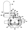
図1、図2、及び、図3は空気室搭載型三連往復ポンプ10のそれぞれ、一部断面を示した側面図、一部断面を示した平面図、及び、正面図である。空気室搭載型三連往復ポンプ10の駆動軸であるクランク軸24は、クランクケース12の幅方向を向きつつクランクケース12に回転自在に支持されている。クランク軸24には、軸方向に等間隔離れて3個所にクランクピン部が形成されている。クランク軸24のクランクピン部には、コンロット26が大端部を回転自在に支持されている。クロスヘッド30は、クランクケース12内に形成されるガイドに沿ってクランクケース12の前後方向に移動自在であり、クロスピン28によってコンロット26の小端部を回転自在に支持している。ピストン32は、クロスヘッド30に固定されており、クランク軸24の回転に伴ってクランクケース12の前後方向に往復動する。コンロット26、クロスピン28、クロスヘッド30、及び、ピストン32は、クランク軸24のクランクピン部に対応してそれぞれ3個ずつ設けられる。空気室搭載型三連往復ポンプ10のポンプ本体は、クランクケース12、シリンダ元金具14、シリンダパイプ16、及び、シリンダ先金具18によって構成される。クランクケース12の前側には、4隅において植え込みボルト20が、それぞれクランクケース12の前後方向に向きを平行に揃えつつ基端側を螺着されている。シリンダ元金具14は、4本の植え込みボルト20を挿通されてクランクケース12の前側に当接している。3個のシリンダパイプ16は、それぞれピストン32の間隔と等しい間隔でピストン32を内部に収容しつつクランクケース12の前後方向を向けて平行に配設され一端をシリンダ元金具14に他端をシリンダ先金具18に接続される。シリンダ先金具18は、4本の植え込みボルト20を挿通されて空気室搭載型三連往復ポンプ10の前端側に位置している。ナット22は、植え込みボルト20の先端部に螺刻されたオスネジに螺合し、クランクケース12との間でシリンダ元金具14、シリンダパイプ16、及び、シリンダ先金具18を挟持し固定する。ピストン32が往復動することによって、空気室搭載型三連往復ポンプ10は、シリンダ元金具14に形成された吸入口34から液体を吸入し、吐出弁38を通じてシリンダ先金具18に形成された吐出口36より加圧された液体を送出する。
【0025】
回転支持部材40は、段部42を吐出口36に嵌入させてシリンダ先金具18に接続され、上下方向に延びる軸線46の周方向に等間隔の位置に設けられるボルト48によってシリンダ先金具18の上部に固定される。Oリング44は、シリンダ先金具18と回転支持部材40との間のシール性を保つ。回転支持部材40は内部に、吐出口36と連通して上下方向に延びる送液路50と送液路50に連なり水平方向に延びる送液路52とを備えている。回転支持部材40には水平方向に延びる嵌合穴が形成されており、回転部材54は、段軸部55を回転支持部材40の嵌合穴に嵌合させて回転支持部材40に回転自在に支持されている。回転支持部材40は、嵌合穴がクランクケース12の幅方向を向くようにシリンダ先金具18に接続されており、回転部材54の段軸部55の軸線60もクランクケース12の幅方向を向いている。円板66は、回転支持部材40の嵌合穴よりも大径をなしており、回転部材54が段軸部55を嵌合穴に嵌合させた状態で、嵌入した側とは反対側より回転部材54の段軸部55に2本のボルト68で固定され、回転部材54の回転支持部材40からの抜けを防止している。回転部材54の内部には、軸線60と垂直方向に延びる送液路56と軸線60の方向に延び送液路56に連通する送液路58とを備えている。回転支持部材40の嵌合穴の壁部には送液路52が開口しており、回転部材54の段軸部55の表面には送液路56が開口しているので、回転部材54が回転支持部材40に対し所定の回転位置範囲にあるときには、吐出口36と送液路58とは連通する。回転部材54の段軸部55には、送液路56が開口する部分の両側においてOリング62及びOリング64がそれぞれ配設され、回転支持部材40と回転部材54との間のシール性を保っている。空気室78は、送液路52及び送液路56の互いの開口面積が最大となる回転位置に回転部材54があるときに起立位置となるよう回転部材54に取付けられており、内部空間を送液路58に対し開口させている。吐出口36と送液路58とが連通して液体が送液路58まで送出されると、空気室78は、内部に収容される空気の膨縮によって液体の脈動を緩衝する。空気室78の脈動緩衝機能は起立位置においては発揮されるが、空気室78を倒伏させると空気室78の内部の空気は流出して、空気室78の脈動緩衝機能は失われる。
【0026】
図4は図1におけるA−A断面の一部を示した図である。回転支持部材40には、軸線60と直交して鉛直方向から所定角度傾斜した直線A−A上において、嵌装穴の外側でかつ円板66の内側となるような軸線60の放射方向位置に、凹所76が設けられている。凹所76には、底部から順に圧縮コイルバネ74、及び、鋼球72が配設されており、圧縮コイルバネ74は鋼球72を円板66の裏側に付勢している。円板66の裏側には、空気室78が起立位置(図1における実線位置)にあるとき、及び、空気室78が頂部をクランクケース12側に向けて90度倒伏させた倒伏位置(図1における破線位置)にあるときに鋼球72と係合するするような軸線60の周方向に90度隔てた2個所の位置にくぼみ70が設けられている。空気室78が前途の起立位置及び倒伏位置にあるときには、圧縮コイルバネ74の付勢により鋼球72がくぼみ70に係合しているので、ある大きさ以上の軸線60回りの外力が加わらなければこれらの保持手段により、空気室78は、前途の起立位置及び倒伏位置を保持される。くぼみ70、鋼球72、圧縮コイルバネ74、及び、凹所76は、軸線60と対称位置に、2個ないし4個設けるようにしても良い。この場合、より安定した保持が図れる。空気室78の軸線60回りの回動は、規制手段(図示せず)により、前途の起立位置と倒伏位置との間の移動に規制される。
【0027】
図5及び図6は薬液散布機2の乗用管理機用トラクタ82に装着した状態を示す平面図及び側面図である。乗用管理機用トラクタ82は、細幅の前輪88及び後輪90を有しており圃場で栽培される作物をまたいでの走行が可能であり、作業者が座って走行その他の操作が可能な運転席84を有している。4節リンク装置96は、乗用管理機用トラクタ82の前部に備えられ、伸縮シリンダ98の伸縮によって前側リンクの昇降が自在である。ブーム装置92は、センタブーム94及びサイドブーム100を有しており、センタブーム94を乗用管理機用トタクタ82の前側において長手方向を乗用管理機用トタクタ82の幅方向と一致させつつ水平方向を向くように、4節リンク装置96の前側リンクに装着されている。サイドブーム100は、作業位置においてセンタブーム94と一直線上となる位置とされるが、軸線102回りに乗用管理機用トラクタ82の前後方向に沿う格納位置へ移動自在である。また、サイドブーム100は、格納位置において先端部が上に向くように傾斜し、さらに、軸線104回りに伸屈自在であり格納性及び運転席への乗降性を高めてある。センタブーム94及びサイドブーム100にはノズル105を等間隔に備えたノズルパイプ103が並設され、ノズルパイプ103は空気室搭載型三連往復ポンプ10により送出される薬液の供給を受けてノズル105より作物に向けて薬液を散布する。
【0028】
乗用管理機用トラクタ82の後部には、3点リンクヒッチを介してフレーム106が装着される。薬液を貯留する薬液タンク110は、平面視において運転席84を囲むような配置が可能な凹部を持つ形状をしており、フレーム106上面のレール部において乗用管理機用トラクタ82の前後方向に移動自在にフレーム106に搭載されている。一方、乗用管理機用トラクタ82には、運転席84の周りに車体床86が設置されており、薬液タンク110は乗用管理機用トラクタ82の前後方向前側に移動されて運転席84を囲む位置において前部を車体床86に、後部をフレーム106にそれぞれ支持されつつ固定手段によって固定される。空気室搭載型三連往復ポンプ10は、フレーム106の後端部において、薬液タンク110の下側でかつ乗用管理機用トラクタ82の後部から出ているPTO軸にクランク軸24が直結可能な上下方向位置に、クランク軸24を乗用管理機用トラクタ82の前後方向に向けた状態でフレーム106に搭載されている。PTO軸には雌側スプラインが、クランク軸24には雄側スプラインがそれぞれ固定されており、雌側スプラインへの雄側スプラインの嵌入により、PTO軸へのクランク軸24の接続がなされている。空気室搭載型三連往復ポンプ10のフレーム106への上下方向の搭載位置は、起立位置にあるときの空気室78の頂部の高さが薬液タンク110の底面よりも高くなる位置で、かつ、倒伏位置にあるときの空気室78の最高点が薬液タンク110の底面よりも低くなる位置となっている。固定位置において薬液タンク110の後面は、空気室78の位置よりも乗用管理機用トラクタ82の前後方向前側にあり、空気室78と薬液タンク110とが干渉することがないので、空気室78は起立位置に置かれ運転可能な状態となっている。
【0029】
図7は図6の主要部の拡大図である。薬液タンク110は乗用管理機用トラクタ82への装着時には、図7において実線で示された位置にある。フレーム106を乗用管理機用トラクタ82から離脱させる場合には、三点リンクヒッチをわずかだけ上昇させて薬液タンク110をフレーム106のみによって支持された状態にし、空気室78を倒伏位置に移動させ、薬液タンク110の固定手段を外す。そして、薬液タンク110を、フレーム106上面のレール部において乗用管理機用トラクタ82の前後方向後側へ移動させて、図7において破線で示された位置とさせ、フレーム106に備えられたスタンドを立てた後、三点リンクヒッチを下降させてフレーム106のスタンドを着地させる。着地させた後、フレーム106を三点リンクヒッチから取り外し、乗用管理機用トラクタ82からの離脱を終了する。
【図面の簡単な説明】
【図1】空気室搭載型三連往復ポンプの一部断面を示した側面図
【図2】空気室搭載型三連往復ポンプの一部断面を示した平面図
【図3】空気室搭載型三連往復ポンプの正面図
【図4】図1におけるA−A断面の一部を示した図
【図5】薬液散布機の乗用管理機用トラクタに装着した状態の概略を示す平面図
【図6】薬液散布機の乗用管理機用トラクタに装着した状態の概略を示す側面図
【図7】図6の主要部の拡大図
【符号の説明】
2 薬液散布機(液体散布装置)
10 空気室搭載型三連往復ポンプ(脈動緩衝装置搭載ポンプ)
12 クランクケース(ポンプ本体)
14 シリンダ元金具(ポンプ本体)
16 シリンダパイプ(ポンプ本体)
18 シリンダ先金具(ポンプ本体)
24 クランク軸(駆動軸)
36 吐出口
54 回転部材
56 送液路
58 送液路
62 Oリング(シール手段)
64 Oリング(シール手段)
70 くぼみ(保持手段)
72 鋼球(保持手段)
74 圧縮コイルバネ(保持手段)
78 空気室(脈動緩衝装置)
82 乗用管理機用トラクタ(トラクタ)
86 車体床(車体)
106 フレーム
110 薬液タンク(液体タンク)[0001]
TECHNICAL FIELD OF THE INVENTION
BACKGROUND OF THE INVENTION 1. Field of the Invention The present invention relates to a pump equipped with a pulsation damping device, such as an air chamber, and a liquid spraying device for sprinkling a liquid such as a chemical solution using the pump equipped with a pulsation damping device.
[0002]
[Prior art]
Reciprocating pumps are often used to pump chemicals in liquid sprayers used as agricultural chemical sprayers, but the liquid pumped by the reciprocating pump contains pulsations, so the reciprocating pump In many cases, an air chamber is mounted as a pulsation damping device for damping the pulsation of a liquid. The air chamber protrudes greatly upward from the pump body of the reciprocating pump. When a reciprocating pump equipped with the air chamber is used for a chemical sprayer such as a boom sprayer, the layout is often hindered.
[0003]
For example, in a chemical sprayer that is detachably mounted on a tractor for a passenger management machine, the optimal arrangement of the chemical tank is determined due to weight balance, but when the driving force of the reciprocating pump is directly connected to the PTO shaft of the tractor Since the installation position of the reciprocating pump on the chemical sprayer is limited to a position connectable to the PTO shaft, the position of the air chamber mounted on the reciprocating pump and the position of the chemical tank overlap.
[0004]
When such a layout is disturbed, remove the air chamber from the reciprocating pump, place the air chamber in an empty space on the chemical sprayer, connect the reciprocating pump and the air chamber with a hose, and buffer the pulsation with the air chamber. A method is used in which the sprayed liquid is used for spraying from a nozzle.
[0005]
[Problems to be solved by the invention]
In a state where the air chamber is mounted on the reciprocating pump, the air chamber is obstructed, and an optimum layout cannot be performed.
[0006]
If the air chamber is removed from the reciprocating pump and connected by a hose, the hose for connecting the air chamber and the reciprocating pump must use a large-diameter hose that can exhibit the pulsation damping function of the air chamber. Piping is not easy, and the connection hose between the air chamber and the reciprocating pump itself is located on the upstream side of the air chamber, so that it is subject to pulsation, which causes vibration and noise.
[0007]
An object of the present invention is to provide a pump equipped with a pulsation damper that does not hinder the layout when the pump is installed in a device, and a chemical sprayer in which the pump equipped with a pulsation damper is laid out in an optimal arrangement. .
[0008]
[Means for Solving the Problems]
The pump (10) equipped with a pulsation damping device according to the present invention buffers the pulsation by receiving the inflow of the pump body (12, 14, 16, 18) and the liquid sent from the pump body (12, 14, 16, 18). A pulsation damping device (78) to be used, and a rotating member (54) rotatably supported by the pump body (12, 14, 16, 18) and fixed to the pulsation damping device (78).
[0009]
When the pulsation damping device (78) protrudes in a specific direction from the space occupied by the pump body (12, 14, 16, 18), the pulsation damping device (10) is installed at a target place when the pulsation damping device-mounted pump (10) is installed. The pulsation damping device fixed to the rotating member (54) is rotated by rotating the rotating member (54) with respect to the pump body (12, 14, 16, 18). (78) can be stored in a direction that does not disturb the user.
[0010]
According to the pulsation damping device mounted pump (10) of the present invention, the rotating member (54) is at least in a predetermined rotation position with respect to the pump body (12, 14, 16, 18). , 16, 18) and a liquid feed path (56, 58) for communicating the pulsation damping device (78) with the discharge port (36).
[0011]
The liquid feeding passages (56, 58) are always connected to the pump body (12, 14, 16, 18) when the rotating member (54) is at an arbitrary rotational position with respect to the pump body (12, 14, 16, 18). It is not always necessary to make the discharge port (36) communicate with the pulsation damping device (78), but it is made to communicate at least at a predetermined rotational position. By connecting the discharge port (36) of the pump body (12, 14, 16, 18) and the pulsation damping device (78), the pulsation damping device (78) is moved from the pump body (12, 14, 16, 18). Since the pulsation damping of the liquid to be sent out can be performed, the operation of the pulsation damping device-equipped pump (10) is performed with the rotating member (54) at this predetermined rotation position. By providing the liquid feeding paths (56, 58) inside the rotating members (56, 58), the pulsation damping function of the pulsation damping device (78) can be used without providing a separate liquid feeding path.
[0012]
According to the pulsation damping device mounted pump (10) of the present invention, the pulsation damping device (78) further moves the rotation member (54) to the upright position when the rotation member (54) is at the predetermined rotation position. Fixed.
[0013]
Some pulsation damping devices (78) cannot exert a pulsation damping function unless they are in an upright state, such as in an air chamber. However, the liquid feeding passages (56, 58) are provided with pump bodies (12, 14, 16, 18). When the rotation member (54) is located at a predetermined rotation position that allows the discharge port (36) of the pulsation damping device (78) to communicate with the pulsation damping device (78), the pulsation damping device (78) is in the standing position, so that the pulsation damping device (78) is in the standing position. Otherwise, it is also possible to use a pulsation damping device (78) which cannot exhibit a pulsation damping function. The operation of the pulsation damper-equipped pump (10) must be performed with the pulsation damper (78) in the upright position, but it is sufficient to temporarily lower the pulsation damper (78) when not operating. There is no problem if it is a place.
[0014]
The pulsation damping device mounted pump (10) of the present invention further includes holding means (70, 72, 74) for holding the pulsation damping device (78) at the standing position and the falling position, respectively.
[0015]
The pulsation damping device (78) is in the upright position during operation, and is in the lying position when it is necessary during non-operation. Since the standing position and the falling position are respectively held by the holding means (70, 72, 74), the rotating member (54) and the pulsation damping device (78) rotate freely due to vibrations or the like, resulting in an unstable state. Can be avoided.
[0016]
The pulsation damping device mounted pump (10) of the present invention further includes sealing means (62, 64) for preventing leakage of liquid from the liquid feed passages (56, 58) when the rotating member (54) rotates. I have.
[0017]
Liquid can be prevented from leaking from the liquid supply passages (56, 58) while rotating the rotating member (54) with respect to the pump body (12, 14, 16, 18) by the sealing means (62, 64). .
[0018]
Liquid spraying apparatus according to the present invention (2) is pulsating cushioning device mounted pump when the frame (106) mounted by a pulse dampener mounted pump (10), pulsating cushioning device (78) is in the upright position (10) Of the pump (10), which is lower than the highest point of the pulsation damping device (78) when the pulsation damping device (78) is in the lying position, and whose bottom surface is placed in the vertical position higher than the highest point of the pulsation damping device mounted pump (10). ) Is provided with a liquid tank (110).
[0019]
In order to arrange the pump (10) and the liquid tank (110) compactly in the frame (106), the vertical mounting position of the pump (10) on the frame (106) is required. It is desirable to approach the bottom of the liquid tank (110) as much as possible. The pulsation damping device (78) mounted on the pulsation damping device mounted pump (10) can be made to fall with respect to the pump body (12, 14, 16, 18). As the peak of the shock absorber pump (10) drops, the pulsation shock absorber pump (10) can be placed on the frame (106) close to the bottom of the liquid tank (110). Since the frame (106) is freely movable in the horizontal direction, the air chamber (78) can be set in the upright position at a horizontal position that does not interfere with the liquid tank (110).
[0020]
According to the liquid spraying device (2) of the present invention, the frame (106) is further mounted on the tractor (82) via the hitch portion, and the drive shaft (24) of the pulsation damping device mounted pump (10) is mounted on the tractor ( The liquid tank (110) is directly connected to the PTO shaft provided in the tractor (82), and the bottom surface is supported by the vehicle body (86) of the tractor (82) when the liquid tank (110) is mounted on the tractor (82).
[0021]
In the mounting operation of the liquid spraying device (2) to the tractor (82), first, the frame (106) is mounted and fixed to the tractor (82) via the hitch portion, and the liquid tank (110) is moved in the horizontal direction. The bottom surface of the tractor (82) at a position supported by the vehicle body (86). By placing the bottom tractor (82) at a position to be supported by the vehicle body (86), the liquid tank (110) can be reliably supported by the tractor (82) and also achieve an optimum weight balance. At this time, since the vertical position of the liquid tank (110) is determined to be a specific position, it is necessary to directly connect the drive shaft (24) of the pump (10) equipped with the pulsation damping device to the PTO shaft of the tractor (82). The pulsation damper pump (10) must be placed on the frame (106) close to the bottom surface of the liquid tank (110), but the pulsation damper (78) is attached to the pump body (12, 14, 16, 18). ), The drive shaft (24) can be directly connected to the PTO shaft.
[0022]
According to the liquid spraying device (2) of the present invention, the liquid tank (110) is further placed at a horizontal position that does not interfere with the pulsation damping device (78) in the upright position when the pulsation damping device mounted pump (10) operates. I will
[0023]
When not in operation, the pulsation damping device (78) can be placed in the lying position, and the liquid tank (110) can be freely moved in the horizontal direction above the pulsation damping device mounted pump (10). During operation, the pulsation damping device (78) is placed in the upright position, so that the pulsation damping device (78) does not exhibit the pulsation damping function unless the pulsation damping device (78) is in the upright position such as an air chamber. Is also good.
[0024]
BEST MODE FOR CARRYING OUT THE INVENTION
Hereinafter, embodiments of the present invention will be described with reference to the drawings.
FIGS. 1, 2, and 3 are a side view, a plan view, and a front view, respectively, showing a partial cross section of the
[0025]
The
[0026]
FIG. 4 is a diagram showing a part of the AA cross section in FIG. The
[0027]
5 and 6 are a plan view and a side view showing a state in which the
[0028]
A
[0029]
FIG. 7 is an enlarged view of a main part of FIG. The
[Brief description of the drawings]
FIG. 1 is a side view showing a partial cross section of an air chamber mounted type triple reciprocating pump. FIG. 2 is a plan view showing a partial cross section of an air chamber mounted type triple reciprocating pump. FIG. FIG. 4 is a front view of a triple reciprocating pump. FIG. 4 is a view showing a part of a cross section taken along line AA in FIG. 1. FIG. 5 is a plan view schematically showing a state in which the chemical liquid sprayer is mounted on a tractor for a riding management machine. 6 is a side view schematically showing a state in which the chemical liquid sprayer is mounted on a tractor for a riding management machine. FIG. 7 is an enlarged view of a main part in FIG.
2 Chemical sprayer (liquid sprayer)
10. Triple reciprocating pump with air chamber (Pump with pulsation damper)
12 Crankcase (pump body)
14 Cylinder base bracket (pump body)
16 Cylinder pipe (pump body)
18 Cylinder tip fitting (pump body)
24 Crankshaft (drive shaft)
36
64 O-ring (sealing means)
70 hollow (holding means)
72 steel ball (holding means)
74 compression coil spring (holding means)
78 air chamber (pulsation damping device)
82 Tractor (Tractor) for passenger management machine
86 Body floor (body)
106
Claims (3)
前記脈動緩衝装置(78)が起立位置にあるときの前記脈動緩衝装置搭載ポンプ(10)の最高点より低くてかつ前記脈動緩衝装置(78)が倒伏位置にあるときの前記脈動緩衝装置搭載ポンプ(10)の最高点より高い上下方向位置に底面を置きつつ水平方向に移動自在に前記フレーム(106)に配設される液体タンク(110)とを有していることを特徴とする液体散布装置。 A pulsation damping device mounted on a frame (106) for buffering pulsation by receiving inflow of a pump body (12, 14, 16, 18) and liquid sent from the pump body (12, 14, 16, 18). A pulsation damping device-equipped pump (10), comprising: a rotation member (54) rotatably supported by the pump body (12, 14, 16, 18) and fixed to the pulsation damping device (78); )When,
The pulsation damping device mounted pump when the pulsation damping device (78) is lower than the highest point and the pulsation damping device of the pulsation damping device mounted pump when in the standing position (10) to (78) is in the collapsed position A liquid tank (110) disposed on the frame (106) so as to be movable in the horizontal direction while placing the bottom surface at a vertical position higher than the highest point of (10). apparatus.
Priority Applications (1)
| Application Number | Priority Date | Filing Date | Title |
|---|---|---|---|
| JP13810099A JP3558552B2 (en) | 1999-05-19 | 1999-05-19 | Liquid spraying device |
Applications Claiming Priority (1)
| Application Number | Priority Date | Filing Date | Title |
|---|---|---|---|
| JP13810099A JP3558552B2 (en) | 1999-05-19 | 1999-05-19 | Liquid spraying device |
Publications (2)
| Publication Number | Publication Date |
|---|---|
| JP2000329059A JP2000329059A (en) | 2000-11-28 |
| JP3558552B2 true JP3558552B2 (en) | 2004-08-25 |
Family
ID=15213960
Family Applications (1)
| Application Number | Title | Priority Date | Filing Date |
|---|---|---|---|
| JP13810099A Expired - Fee Related JP3558552B2 (en) | 1999-05-19 | 1999-05-19 | Liquid spraying device |
Country Status (1)
| Country | Link |
|---|---|
| JP (1) | JP3558552B2 (en) |
-
1999
- 1999-05-19 JP JP13810099A patent/JP3558552B2/en not_active Expired - Fee Related
Also Published As
| Publication number | Publication date |
|---|---|
| JP2000329059A (en) | 2000-11-28 |
Similar Documents
| Publication | Publication Date | Title |
|---|---|---|
| US7980490B2 (en) | Nozzle body apparatus | |
| KR101845344B1 (en) | Folder type crop duster for tractor loading | |
| US6047901A (en) | Spray boom support assembly | |
| US4505067A (en) | Apparatus for hydraulic tree injection | |
| US20170020121A1 (en) | Boom vibration control device and boom sprayer | |
| KR102037176B1 (en) | Pesticide sprayer of tractor | |
| CN218451326U (en) | Spray rod spraying machine with corn and soybean composite mode | |
| JP3558552B2 (en) | Liquid spraying device | |
| KR20110007506A (en) | Unmanned duster | |
| JP2010051274A (en) | Control working machine | |
| JP2020061974A (en) | Chemical spraying device | |
| US6779688B1 (en) | Catch basin for a concrete pumping device | |
| KR20180116557A (en) | A liquid spraying device | |
| JP4627223B2 (en) | Liquid spraying device | |
| KR20090097359A (en) | Chemical spraying device | |
| CN204811647U (en) | Boom sprayer | |
| KR20200026495A (en) | Pest control apparatus for multi-direction | |
| CN221128573U (en) | Pesticide sprinkler device is planted to maize | |
| JP2521503Y2 (en) | Power sprayer | |
| JP4699864B2 (en) | Boom sprayer | |
| CN216280120U (en) | High-pressure decontamination machine | |
| JP3960770B2 (en) | Power working machine | |
| US10801179B2 (en) | Hydraulic fluid storage tank including quick connect coupling | |
| CN218868936U (en) | a spraying device | |
| CN222840344U (en) | Weeding and sterilizing vehicle |
Legal Events
| Date | Code | Title | Description |
|---|---|---|---|
| TRDD | Decision of grant or rejection written | ||
| A01 | Written decision to grant a patent or to grant a registration (utility model) |
Free format text: JAPANESE INTERMEDIATE CODE: A01 Effective date: 20040518 |
|
| A61 | First payment of annual fees (during grant procedure) |
Free format text: JAPANESE INTERMEDIATE CODE: A61 Effective date: 20040518 |
|
| R150 | Certificate of patent or registration of utility model |
Free format text: JAPANESE INTERMEDIATE CODE: R150 |
|
| FPAY | Renewal fee payment (event date is renewal date of database) |
Free format text: PAYMENT UNTIL: 20090528 Year of fee payment: 5 |
|
| FPAY | Renewal fee payment (event date is renewal date of database) |
Free format text: PAYMENT UNTIL: 20090528 Year of fee payment: 5 |
|
| FPAY | Renewal fee payment (event date is renewal date of database) |
Free format text: PAYMENT UNTIL: 20100528 Year of fee payment: 6 |
|
| FPAY | Renewal fee payment (event date is renewal date of database) |
Free format text: PAYMENT UNTIL: 20100528 Year of fee payment: 6 |
|
| FPAY | Renewal fee payment (event date is renewal date of database) |
Free format text: PAYMENT UNTIL: 20110528 Year of fee payment: 7 |
|
| FPAY | Renewal fee payment (event date is renewal date of database) |
Free format text: PAYMENT UNTIL: 20120528 Year of fee payment: 8 |
|
| FPAY | Renewal fee payment (event date is renewal date of database) |
Free format text: PAYMENT UNTIL: 20130528 Year of fee payment: 9 |
|
| LAPS | Cancellation because of no payment of annual fees |