JP3558397B2 - Thermometer - Google Patents
Thermometer Download PDFInfo
- Publication number
- JP3558397B2 JP3558397B2 JP00547095A JP547095A JP3558397B2 JP 3558397 B2 JP3558397 B2 JP 3558397B2 JP 00547095 A JP00547095 A JP 00547095A JP 547095 A JP547095 A JP 547095A JP 3558397 B2 JP3558397 B2 JP 3558397B2
- Authority
- JP
- Japan
- Prior art keywords
- light guide
- infrared sensor
- temperature
- space
- infrared
- Prior art date
- Legal status (The legal status is an assumption and is not a legal conclusion. Google has not performed a legal analysis and makes no representation as to the accuracy of the status listed.)
- Expired - Fee Related
Links
- 210000003454 tympanic membrane Anatomy 0.000 claims description 26
- 230000002093 peripheral effect Effects 0.000 claims description 18
- 238000012937 correction Methods 0.000 claims description 15
- 239000000523 sample Substances 0.000 claims description 15
- 210000000613 ear canal Anatomy 0.000 claims description 11
- 239000000463 material Substances 0.000 claims description 10
- 230000005855 radiation Effects 0.000 claims description 6
- 230000000116 mitigating effect Effects 0.000 claims description 2
- 238000009751 slip forming Methods 0.000 claims description 2
- 238000005259 measurement Methods 0.000 description 13
- 230000036760 body temperature Effects 0.000 description 10
- 238000009529 body temperature measurement Methods 0.000 description 4
- 238000004364 calculation method Methods 0.000 description 4
- 230000000694 effects Effects 0.000 description 4
- 229910052751 metal Inorganic materials 0.000 description 4
- 239000002184 metal Substances 0.000 description 4
- 230000005540 biological transmission Effects 0.000 description 3
- 238000010586 diagram Methods 0.000 description 3
- PXHVJJICTQNCMI-UHFFFAOYSA-N Nickel Chemical compound [Ni] PXHVJJICTQNCMI-UHFFFAOYSA-N 0.000 description 2
- 238000013500 data storage Methods 0.000 description 2
- 238000001514 detection method Methods 0.000 description 2
- PCHJSUWPFVWCPO-UHFFFAOYSA-N gold Chemical compound [Au] PCHJSUWPFVWCPO-UHFFFAOYSA-N 0.000 description 2
- 229910052737 gold Inorganic materials 0.000 description 2
- 239000010931 gold Substances 0.000 description 2
- 238000007747 plating Methods 0.000 description 2
- RYGMFSIKBFXOCR-UHFFFAOYSA-N Copper Chemical compound [Cu] RYGMFSIKBFXOCR-UHFFFAOYSA-N 0.000 description 1
- BQCADISMDOOEFD-UHFFFAOYSA-N Silver Chemical compound [Ag] BQCADISMDOOEFD-UHFFFAOYSA-N 0.000 description 1
- 229920000122 acrylonitrile butadiene styrene Polymers 0.000 description 1
- 239000000956 alloy Substances 0.000 description 1
- 229910045601 alloy Inorganic materials 0.000 description 1
- 229910052782 aluminium Inorganic materials 0.000 description 1
- XAGFODPZIPBFFR-UHFFFAOYSA-N aluminium Chemical compound [Al] XAGFODPZIPBFFR-UHFFFAOYSA-N 0.000 description 1
- 210000004004 carotid artery internal Anatomy 0.000 description 1
- 238000006243 chemical reaction Methods 0.000 description 1
- 230000001276 controlling effect Effects 0.000 description 1
- 229910052802 copper Inorganic materials 0.000 description 1
- 239000010949 copper Substances 0.000 description 1
- 238000013461 design Methods 0.000 description 1
- 229910052732 germanium Inorganic materials 0.000 description 1
- GNPVGFCGXDBREM-UHFFFAOYSA-N germanium atom Chemical compound [Ge] GNPVGFCGXDBREM-UHFFFAOYSA-N 0.000 description 1
- 239000011521 glass Substances 0.000 description 1
- 102000054999 human core Human genes 0.000 description 1
- 108700026469 human core Proteins 0.000 description 1
- 238000003780 insertion Methods 0.000 description 1
- 230000037431 insertion Effects 0.000 description 1
- 239000004973 liquid crystal related substance Substances 0.000 description 1
- QSHDDOUJBYECFT-UHFFFAOYSA-N mercury Chemical compound [Hg] QSHDDOUJBYECFT-UHFFFAOYSA-N 0.000 description 1
- 229910052753 mercury Inorganic materials 0.000 description 1
- 238000000034 method Methods 0.000 description 1
- 229910052759 nickel Inorganic materials 0.000 description 1
- 230000003287 optical effect Effects 0.000 description 1
- 230000001105 regulatory effect Effects 0.000 description 1
- 229920005989 resin Polymers 0.000 description 1
- 239000011347 resin Substances 0.000 description 1
- 229910052710 silicon Inorganic materials 0.000 description 1
- 239000010703 silicon Substances 0.000 description 1
- 229910052709 silver Inorganic materials 0.000 description 1
- 239000004332 silver Substances 0.000 description 1
- 125000006850 spacer group Chemical group 0.000 description 1
- 229920005992 thermoplastic resin Polymers 0.000 description 1
- 230000000007 visual effect Effects 0.000 description 1
Images


Landscapes
- Radiation Pyrometers (AREA)
- Measuring And Recording Apparatus For Diagnosis (AREA)
Description
【0001】
【産業上の利用分野】
本発明は非接触による方法で測定する体温計に係り、特にプローブ先端部を耳穴に挿入して鼓膜又は鼓膜近傍の外耳道の温度(即ち、実質的な鼓膜の温度)を正確に計測する体温計に関するものである。
【0002】
【従来の技術】
近年になり、旧来からのガラス体温計に代わり、電子体温計が普及している。この種の電子体温計の特徴としては、多少の外力を加えても壊れにくく、且つ水銀を使用していないことから安全性に優れる検温を可能としており、一般家庭に多く普及している。これらの電子体温計の検温の際に必要な時間は、予測式機能を有した電子体温計においては約1〜2分である。また、予測式機能を具備していない電子体温計によれば、さらに時間を要している。したがって、このような電子体温計においては、口中や腋下の検温において、各測定部位が熱的平衡に達するまでの時間が必要である。
【0003】
そこで、最近になり、鼓膜や鼓膜近傍の外耳道(即ち、実質的な鼓膜の温度)からの赤外線放射を有効的に利用した非接触式体温計が提案されている。この非接触式体温計は、所定温度に上昇している物体乃至生体は全て赤外線を放射する現象を利用しているので、上記の電子体温計のように測定部位と温度センサの間において熱的平衡状態になるまで待つことなく、瞬時に物体温度または生体の体温を計測することができる。
【0004】
一方、生体の体温測定部位としての鼓膜は、内頸動脈の温度を正確に反映していることが近年明らかになり、人の中核温を測定できる部位として注目されている。そこで、鼓膜温度を検出する非接触式体温計を使用して中核温を反映した鼓膜温を安全に極めて短時間で測定することが可能になった。また、このような非接触式体温計の内、赤外線センサによる温度検出以外に赤外線センサ自体の周辺の温度等を観測して、体温値を正確に算出する体温計が、例えば特開平2−35322号公報において提案されており、より正確な体温を測定することが可能になっている。
【0005】
【発明が解決しようとする課題】
しかしながら、上記の従来の非接触式体温計によれば、赤外線センサ周辺の熱バランスの崩れがあるので、熱バランスの安定を待つために一回の測定毎に長いインターバル時間を必要とする不具合があった。また、測定値に、温度ドリフトを生じてしまうことがあった。
【0006】
一方、上述の特開平2−35322号公報の「放射体温計」によれば、赤外線センサの熱バランスを事前に計測して、温度ドリフトを軽減して、測定の待ち時間を一部不要とした点で優れている。
【0007】
しかしながら、このような放射体温計によれば、特に赤外線センサ周辺の構造において、熱的平衡を早める構造ではない。具体的には赤外線センサ自身の温度を的確に計測できる構造ではないために、測定毎の待ち時間(インターバル時間)をほとんど「ゼロ」にするための条件が制限される問題点がある。
【0008】
また、この「放射体温計」の構造によれば、一度大きく熱バランスを崩した場合には、各構成部材の熱伝導と比熱の関係により、再度計測できる正常な状態に復帰するために要する時間が長くなる問題点がある。
【0010】
したがって、本発明は上記の問題点に鑑みて成されたものであり、鼓膜または鼓膜近傍の外耳道(即ち、実質的な鼓膜の温度)を非接触で検温する体温計において、測定毎の待ち時間を実質上無くすことにより使用上の不便さを解消でき、且つ熱バランスを崩した後にも温度ドリフトが殆ど発生せず通常どおりに使用することができる体温計の提供を目的とする。
【0017】
【課題を解決するための手段】
上記目的を達成するために本発明の体温計は以下の構成を備える。即ち、生体の鼓膜及びまたは鼓膜近傍の外耳道部位の温度を非接触で計測する体温計であって、前記鼓膜及びまたは鼓膜近傍の外耳道部位に向けて指向される開口部と、該開口部から連続形成される内周面部とを形成したプローブ部材と、前記開口部から離間した内部において配設されるとともに前記鼓膜または外耳道部位から放射される赤外線を検出する赤外線センサと、前記開口部から前記赤外線センサの受光部まで赤外線を案内するとともに端部において第1の空間部を介して前記赤外線センサの受光部まで赤外線を案内するために前記端部から延設される傘状部と、該傘状部から延設されるフランジ部を一体形成し、該フランジ部内側に前記第1の空間部を形成するとともに、前記フランジ部を前記赤外線センサの容器に対する径方向に締め込むことで変形して前記容器に隙間なく接触させるすり割り部を備えた導光部と、前記赤外線センサと前記導光部の間において十分な熱的接触状態を得るために前記フランジ部を締結する締結部材と、熱的平衡の高速化のための第2の空間部を前記内周面部との間で確保して、前記導光部に密着して固定されることで、前記導光部自体及びまたはその近傍の温度を検出する補正用温度センサと、前記赤外線センサの周囲に設けられる第3の空間部と、前記赤外線センサに密着して固定されて前記赤外線センサ自体の温度を検出する基準用温度センサと、前記赤外線センサと基準用温度センサと補正用温度センサとからの出力に基づいて温度値の算出を行う制御手段と、前記温度値を表示する表示手段とを具備することを特徴とする。
【0018】
また、体温計は、前記内周面部と前記導光部の外周面との間において、熱的平衡の高速化をはかるための第4の空間部をさらに設けることを特徴とする。
【0020】
また、体温計は、前記締結部材を、前記赤外線センサヘの熱的影響をほぼ均一にするために熱伝導性に優れ、かつ略十分な熱容量を有する材質から形成し、かつ前記第3の空間部を一体形成したことを特徴とする。
【0021】
また、体温計は、前記導光部が、熱伝導性に優れ、かつ熱伝導の均一化を図るために板厚が全体に渡り略均一な同一材料から構成されることを特徴とする。
【0022】
また、体温計は、前記導光部の先端部において、赤外線を透過する窓部材と、該窓を保持する保持部材とをさらに設けたことを特徴とする。
【0023】
また、体温計の前記補正用温度センサは、前記第1の空間部を形成する前記傘状部の境目と前記開口部との間の所定位置で、前記導光部の外周面部位に密着されて固定されることを特徴とする。
【0024】
【作用】
以上の構成により、赤外線センサ及び赤外線センサ自身の温度を測定する基準用温度センサの温度データから計算した温度値データに、基準用温度センサと、導光部自体及びまたはその近傍の温度を測定する補正用センサからの温度データから計算した温度補正値を加えることで、常時、測定待ち時間のほとんどない温度測定ができ、かつ例えば赤外線センサの周辺部位において熱バランスを崩した時に発生する温度ドリフトを補正することができるように働く。
【0025】
【実施例】
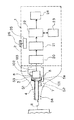
以下、添付図面を参照して本発明の好適な実施例を詳細に説明すると、図1は体温計1の中心断面図であって光学系と温度センサ周辺のみを示し、体温計のその他の処理系は省略して示した図である。
【0026】
本図において、破線図示の本体部2の先端には図示の形状からなる所定樹脂から構成される中空のプローブ先端部材3が固定されている。このプローブ先端部材3の材質は、ABS樹脂などの一般に使用される熱可塑性樹脂素材であれば特に素材は問われず、断熱機能を持つ素材であるならばより望ましい。
【0027】
このプローブ先端部材3は、略円形形状の中空管からなり、図示のように外形が先細り形状の形状部3aを一体形成しており、鼓膜及びまたは鼓膜近傍の外耳道(即ち、実質的に鼓膜)から放射される赤外線を入光するための開口部3cをその先端部位において穿設する一方、この開口部3cから連続し、内径が略等しい内周面3bを形成している。この内周面3bは、図示のようにプローブ本体2の端部に至るまでに図示のように次第に内径が増加するように構成されており、後述する補正用温度センサ7との間に十分な空間部S2を設けることができるようにしている。
【0028】
また、このプローブ先端部材3の内周面3bにはその対称位置において、図中の破線図示の取り付け部3eが一体形成されており、後述するホルダー部品6を二点鎖線で示されるストッパー部品10を介して2本のネジ11(破線図示)により固定(係止)することにより、このホルダー部品6内において固定される赤外線センサ5と、このセンサ5に固定される導光部4とを図示の所定位置に保持するようにしている。また、開口部3cの回りには半径1ミリ前後のR面取りをした面取り部3dが形成されており、挿入時において患者に苦痛を与えないように配慮している。
【0029】
一方、赤外線センサ5は、赤外線を電気信号に変換する多数の熱電対(サーモパイル)を図示のような形状の金属容器に内蔵した、所謂キャンタイプであって、上記の導光部4の内部を通過して入光する赤外線Rを破線図示の入光部5aからサーモパイル上に集めて赤外線Rを電気信号に変換してから信号線103を介して外部に取り出すように構成されている。尚、この赤外線センサ5は、その他サーミスタボロメータや焦電素子などの赤外線を感知できるセンサならばいかなる形式でも良い。また、この赤外線センサ5は、ホルダー部品6内の所定位置に固定されるように、スペーサ部品15を図示のように設けている。
【0030】
次に、赤外線センサ5の容器の側面部位には、基準用温度センサ8が密着した状態で設けられており、赤外線センサ5の温度を計測するように構成されておりフレキシブル印刷回路(FPC)または電熱的影響の小さい細線を用いた信号線102を介して制御回路基板に入力可能にしている。
【0031】
また、導光部4の側面部位であって、上記のように空間部S2を確保した部位には、補正用温度センサ7が密着して設けられており、導光部4の自体の温度を計測可能にする一方、上記と同じFPCの信号線101を介して検出信号を制御回路に入力可能に構成している。以上の補正用温度センサ7、8用には、サーミスタやダイオードなどの小さな熱容量の温度センサであればいかなるものでも良く、さらに熱電対からなるセンサを使用しても良い。
【0032】
ここで、補正用温度センサ7の配設位置としては、導光部4の開口部4cから、先端方向に約2mmの部位が上記の空間部S2の相互関係から最も良いが、この部位に限定されず開口部4cの位置から赤外線センサ5側の−3mm〜開口部4a側の10mmの範囲であればその取り付け位置はどこでも良く、要するに空間部S2を確保できる部位であればどこでも良い。
【0033】
続いて、図2は図1の導光管4の外観斜視図であって、図1に図2をさらに参照して説明する。赤外線センサ5との熱的接触をより良好にして、さらに赤外線センサ5の入光部5aの視野に熱的に均一な開口部4cが望むようにするために、導光部4は開口部4cから皿状に広がる傘部4kの縁部において連続形成されるフランジ部4fであって、内径寸法が赤外線センサ5のキャンの外形寸法に嵌合するようにした部位が連続形成されており、赤外線センサ5の感温部方向を包む形状となっている。
【0034】
また、この導光部4は、図1においてその一部のみがセンサ5に対して接触するようにして、センサ5自体の熱バランスが崩れないようにするために上記の傘部の内部に空間S1を設けてある。また、導光部4は、筒状に形成されてなり、金、銅や銀またはそれらの合金などのように熱伝導性に優れる金属またはこれらの金属をメッキしたものが使用され、また外耳道に挿入した際に、外耳道からの熱が直接的に伝わらないようにするために、先き細り形状部3aの内周面3bと導光部4の外周面との間に空間S4が設けられている。導光部4とプローブ先端部材3の中心を略同一にするために4aと3dを一部が接触するように構成しても良い。また、導光部4は、ホルダー部品6により赤外線センサ5の容器の外周面に対して締めつけられる機能を持つことで、相互間の熱的接触をより向上させ、かつ赤外線センサ5の視野内において、熱伝導がバランス良く均一にできるようにするために、導光部4の肉厚は全体的にほぼ均一に構成されており、かつ同一材料の連続構造からなり、また赤外線センサ5との熱的接触を高めるために、センサ5の容器の外形寸法を内径寸法とするフランジ部4eとすり割り部4fが90度間隔で形成されており、後述のように赤外線センサ5をセットした後に、ホルダー部品6を締めつけることにより、すり割り部4fを境にして各フランジ部4eが容器側に変形して相互に隙間無く接触できるようにしている。さらに、図示のように略円形の中空管状に形成される導光部4の内部を通過する赤外線の熱的損失分を少なくするために、内面部4b及び4k裏面部位をほぼ鏡面になるように仕上げられてからニッケルメッキ後に金メッキ処理が施されている。
【0035】
次に、図3は導光部の開口部4a近辺の中心断面図である。本図において、導光部4の開口部4aには内部に異物の混入を防ぐための赤外線透過窓12が設けられており、開口部13aを形成した窓ホルダー13により図示の位置に固定されている。この赤外線透過窓12は、シリコンやゲルマニウム等の赤外線透過素材ならなんでも良く、特に導光部4への影響を小さくする材質が良い。また、プローブ先端部材3の先端部3aを外耳道へ挿入した時の、導光部4に対する熱的影響を極力少なくするために、窓ホルダー13は内周面3bに接触しないことが望ましく、空間部S4をこの部位に延長することで達成できる。
【0036】
続いて、図4は図1のA‐A矢視断面図であって、ホルダー部品6のみ示した図である。また、図5は図4のB‐B矢視断面図である。先ず、図4において、ホルダー部品6は、上記の導光部4のフランジ部4eに連続する傘部の縁部を保持するための開口部6bが図示のように形成される一方、この開口部6bにおいて上記の基準用温度センサ8を空間部S3を確保しつつ収容するための溝部62が形成されている。また、この溝部62の対向側にはすり割り部6cが形成されれており、このすり割り部6cを矢印H方向にネジ11を使用して径方向に締め込むためのネジ穴部6dに対してネジ締めを行うことにより、上記の導光管4を赤外線センサ5の容器に対して密着するようにしている。尚、ホルダー部品は、熱伝導性に優れ、かつ熱容量を十分に得るためにアルミを使用している。
【0037】
続いて、図5をさらに参照して、図1において破線図示の取り付け部3eに対して潜入される形状部61が図示のように形成されており、ネジ11を各穴部6eに対して挿入してから螺合されるように構成されている。また、ホルダー部品6の内部構成は図示のように、開口部6bから連続形成される傾斜面部6fに対して導光部4のフランジ部が位置規制されて固定されるように構成されている。以上の構成により、基準用温度センサ8は赤外線センサ12の側面に密着するとともに、その他の部材には溝部62の空間により接触しないように設けられ、かつ上記のように熱的接触の向上を図ったので、センサ5のみの温度を正確に検出し、その他の部材からの温度の影響を殆ど受けなくなる。
【0038】
最後に、図6は体温計の機能ブロック図である。本図において、温度計1は本体部2と、この端部において固定されるプローブ先端部3を外装品として構成されており、プローブ先端部3の内部にホルダー部品を使用して赤外線センサ5が固定される一方、導光部4の側面には補正用温度センサ7が、また赤外線センサ5には基準用温度センサ8が夫々配設されており、信号線101、102を介して各センサの温度情報を電気的に増幅する信号増幅部20に接続されている。また、この信号増幅部20は、増幅波形のアナログ的な電気信号をディジタル化して、数値的データに変換する信号変換部21に接続されている。そして、信号変換部21には演算制御部22であって、体温値計算や各機能の制御を行う制御部に接続されている。また、この演算制御部22にはデータ記憶部23であって、演算制御部22において、体温値の計算を行う際に、必要となる各種係数を蓄積する機能を有する記憶部に接続されている。また、このデータ記憶部23は、体温値の計算途中に発生したデータを一時的に蓄積する機能や体温値測定における前回値を蓄積する機能も有している。そして、演算制御部22には表示部24であって、温度値やその他の制御情報を液晶、発光ダイオード等により表示する機能を有する機能部に接続されている。
【0039】
以上の構成において、赤外線センサ5と、赤外線センサ5自身の温度をほぼ正確に計測する基準用温度センサ8と、導光部4の近傍に配置した補正用温度センサ7の測定値から、温度値の計算を行い、所定演算した後に温度表示することができる。
【0040】
以上説明した実施例の構成によれば、赤外線センサと、赤外線センサ自身の温度を観測する基準用温度センサと、導光部近傍に配置した補正用温度センサからの温度データを測定し、体温値の計算を行うことにより、赤外線センサ周辺の熱バランスが崩れている場合でも体温の計測ができる結果、測定毎の待ち時間を略ゼロにして、連続的にまたは各個人に対して短時間(インターバル時間)で順次体温の測定を行うことができるようになり、非接触式温度計を特に体温計として使用した場合に効果を発揮できる。
【0041】
尚、温度計は体温計に限定されず、非接触で物体の温度を測定するあらゆる工業分野において使用可能であり、特にインターバル時間の短い測定分野において効果的であることは言うまでもない。
【0042】
また、上記の実施例によれば、赤外線センサ5に市販品を使用した関係からこのセンサに固定される導光管4を別部品として設けたが、少なくとも上述した第1から第3の空間部を形成できるように一体構成するものであれば、何でも良く一体構成とすることでさらに設計上の自由度が確保でき、さらなるコストダウンを図れる。したがって、少なくとも特許請求の範囲に規定される種々の別構成が可能であることは言うまでもない。
【0044】
【発明の効果】
以上のように本発明によれば、鼓膜または外耳道を非接触式で測定する体温計において、測定毎の待ち時間を実質上無くすことにより使用上の不便さを解消でき、且つ熱バランスを崩した後にも熱伝導をバランス良く均一に行うことで温度ドリフトが殆ど発生せず略通常どおりに使用することができる体温計を提供できる。
【0045】
【図面の簡単な説明】
【図1】実施例に係る体温計のプローブ部分の要部構成を示した中心断面図である。
【図2】導光管4の外観斜視図である。
【図3】導光管4の先端部位の中心断面図である。
【図4】図1のA‐A矢視断面図であって、ホルダー部品6のみ示した図である。
【図5】図4のB‐B矢視断面図であって、ホルダー部品6のみ示した図である。
【図6】体温計の機能構成を示したブロック図である。
【符号の説明】
1 温度計
2 プローブ本体
3 プローブ先端部
3c 開口部
4 導光部
5 赤外線センサ
6 ホルダー部品
7 補正用温度センサ
8 基準用温度センサ
12 赤外線通過窓
13 窓ホルダ
S1 空間部(第1の空間部)
S2 空間部(第2の空間部)
S3 空間部(第3の空間部)
S4 空間部(第4の空間部)
R 赤外線[0001]
[Industrial applications]
The present invention relates to a thermometer for measuring by a non-contact method, and more particularly to a thermometer for accurately measuring a temperature of an eardrum or an external auditory meatus near an eardrum (ie, a substantial temperature of an eardrum) by inserting a probe tip into an ear canal. It is.
[0002]
[Prior art]
In recent years, electronic thermometers have become widespread in place of traditional glass thermometers. As a characteristic of this type of electronic thermometer, it is hardly broken even when a small external force is applied, and since it does not use mercury, it is possible to perform a temperature measurement with excellent safety, and is widely used in ordinary households. The time required for measuring the temperature of these electronic thermometers is about 1 to 2 minutes in an electronic thermometer having a predictive function. Further, according to the electronic thermometer without the predictive function, more time is required. Therefore, in such an electronic thermometer, in the temperature measurement in the mouth and under the armpit, time is required until each measurement site reaches thermal equilibrium.
[0003]
Therefore, recently, a non-contact type thermometer that effectively utilizes infrared radiation from the eardrum or the external auditory meatus near the eardrum (ie, substantially the temperature of the eardrum) has been proposed. Since this non-contact thermometer utilizes the phenomenon that all objects or living bodies that have risen to a predetermined temperature emit infrared light, a thermal equilibrium state between the measurement site and the temperature sensor as in the electronic thermometer described above. in until no one waiting, it is possible to measure the body temperature of the object temperature or biological instantaneously.
[0004]
On the other hand, it has recently been found that the eardrum as a body temperature measurement site of a living body accurately reflects the temperature of the internal carotid artery, and is attracting attention as a site where a human core temperature can be measured. Thus, it has become possible to safely measure the eardrum temperature reflecting the core temperature in an extremely short time by using a non-contact thermometer for detecting the eardrum temperature. Among such non-contact thermometers, a thermometer that accurately measures a body temperature by observing a temperature around the infrared sensor itself in addition to temperature detection by an infrared sensor is disclosed in, for example, JP-A-2-35322. And it has become possible to measure more accurate body temperature.
[0005]
[Problems to be solved by the invention]
However, according to the above-mentioned conventional non-contact type thermometer, since the heat balance around the infrared sensor is lost, there is a problem that a long interval time is required for each measurement in order to wait for the stability of the heat balance. Was. In addition, a temperature drift may occur in the measured value.
[0006]
On the other hand, according to the "radiation thermometer" of JP-A-2-35322 described above, the thermal balance of the infrared sensor is measured in advance, the temperature drift is reduced, and the waiting time for the measurement is partially eliminated. Is excellent.
[0007]
However, such a radiation thermometer does not have a structure that accelerates thermal equilibrium, particularly in a structure around an infrared sensor. Specifically, there is a problem that conditions for setting the waiting time (interval time) for each measurement to almost “zero” are limited because the structure is not such that the temperature of the infrared sensor itself can be accurately measured.
[0008]
In addition, according to the structure of the "radiation thermometer", once the thermal balance is greatly lost, the time required to return to a normal state where it can be measured again due to the relationship between the heat conduction and the specific heat of each component. There is a problem that becomes longer.
[0010]
Therefore, the present invention has been made in view of the above problems, and in a thermometer that non-contactly measures the temperature of the eardrum or the ear canal in the vicinity of the eardrum (that is, the substantial temperature of the eardrum), the waiting time for each measurement is reduced. It is an object of the present invention to provide a thermometer which can eliminate inconvenience in use by substantially eliminating it, and can be used as usual with almost no temperature drift even after heat balance is lost.
[0017]
[Means for Solving the Problems]
In order to achieve the above object, a thermometer of the present invention has the following configuration. That is, a thermometer for non-contact measurement of the temperature of the eardrum and / or the ear canal region near the eardrum of the living body, and an opening directed toward the eardrum and / or the ear canal region near the eardrum and continuously formed from the opening. A probe member having an inner peripheral surface portion to be formed, an infrared sensor disposed inside the space separated from the opening and detecting infrared radiation emitted from the eardrum or the ear canal portion, and the infrared sensor from the opening a cone-shaped part extending from said end portion to through the first space portion for guiding the infrared ray to the light receiving portion of the infrared sensor at an end with guiding the infrared to the light receiving portion of the bevel-shaped portion And a first space portion is formed inside the flange portion, and the flange portion is formed in a radial direction with respect to a container of the infrared sensor. A light guide portion provided with a slit portion which is deformed by being tightened to make contact with the container without any gap, and the flange portion for obtaining a sufficient thermal contact state between the infrared sensor and the light guide portion. By securing a second space part for speeding up thermal equilibrium between the fastening member and the inner peripheral surface part and fixing the second space part in close contact with the light guide part, and correcting the temperature sensor for detecting the light unit itself and or the temperature in the vicinity thereof, and a third space portion that is provided around the infrared sensor, the temperature of the infrared sensor itself in close contact with and fixed to said infrared sensor Reference temperature sensor for detecting the temperature, control means for calculating a temperature value based on outputs from the infrared sensor, the reference temperature sensor, and the correction temperature sensor, and display means for displaying the temperature value. It is characterized by doing.
[0018]
Further, thermometer, characterized by further providing a fourth space to measure fraud and mitigating risk speed thermal equilibrium between the outer peripheral surface of the light guide portion and the inner peripheral surface.
[0020]
Further, the thermometer, the fastening member is formed of a material having excellent thermal conductivity to make the thermal effect on the infrared sensor substantially uniform, and having a substantially sufficient heat capacity, and the third space portion is formed. It is characterized by being integrally formed.
[0021]
Further, the thermometer is characterized in that the light guide section is made of the same material having excellent heat conductivity and a substantially uniform plate thickness over the whole in order to achieve uniform heat conduction.
[0022]
In the thermometer, a window member that transmits infrared rays and a holding member that holds the window are further provided at a distal end portion of the light guide unit.
[0023]
Further, the correction temperature sensor of the thermometer is a predetermined position between the boundary and the opening of the cone-shaped part forming the first space, it is in close contact with the outer peripheral surface portion of the light guide portion It is characterized by being fixed.
[0024]
[Action]
With the above configuration, the reference temperature sensor and the temperature of the light guide unit itself and / or the vicinity thereof are measured on the temperature value data calculated from the temperature data of the infrared sensor and the reference temperature sensor that measures the temperature of the infrared sensor itself. By adding the temperature correction value calculated from the temperature data from the correction sensor, temperature measurement with almost no measurement waiting time can be performed at all times, and for example, temperature drift that occurs when heat balance is lost in the vicinity of the infrared sensor is reduced. It works so that it can be corrected.
[0025]
【Example】
Hereinafter, a preferred embodiment of the present invention will be described in detail with reference to the accompanying drawings. FIG. 1 is a central sectional view of a
[0026]
In this figure, a hollow
[0027]
The
[0028]
The inner
[0029]
On the other hand, the infrared sensor 5 is of a so-called can type in which a large number of thermocouples (thermopiles) for converting infrared rays into electric signals are built in a metal container having a shape as shown in the drawing, and the inside of the
[0030]
Next, a
[0031]
In addition, a
[0032]
Here, as the disposition position of the
[0033]
Next, FIG. 2 is an external perspective view of the
[0034]
In addition, the
[0035]
Next, FIG. 3 is a center sectional view near the
[0036]
Subsequently, FIG. 4 is a cross-sectional view taken along the line AA of FIG. 1, and is a diagram illustrating only the
[0037]
Subsequently, referring further to FIG. 5, a
[0038]
Finally, FIG. 6 is a functional block diagram of the thermometer. In this figure, a
[0039]
In the above configuration, the temperature value is obtained from the measured values of the infrared sensor 5, the
[0040]
According to the configuration of the embodiment described above, the temperature data from the infrared sensor, the reference temperature sensor for observing the temperature of the infrared sensor itself, and the correction temperature sensor disposed near the light guide section are measured, and the body temperature value is measured. By performing the above calculation, the body temperature can be measured even when the thermal balance around the infrared sensor is disturbed. As a result, the waiting time for each measurement is reduced to almost zero, and continuously or individually for a short time (interval) Time), the body temperature can be measured sequentially, and the effect can be exerted particularly when the non-contact type thermometer is used particularly as a thermometer.
[0041]
The thermometer is not limited to a thermometer, but can be used in any industrial field where the temperature of an object is measured in a non-contact manner. It goes without saying that the thermometer is particularly effective in the field of measurement with a short interval time.
[0042]
Further, according to the above-described embodiment, the
[0044]
【The invention's effect】
As described above, according to the present invention, in a thermometer that measures a tympanic membrane or an ear canal in a non-contact manner, it is possible to eliminate inconvenience in use by substantially eliminating a waiting time for each measurement, and after breaking a heat balance. Also, it is possible to provide a thermometer that can be used almost in a normal manner with almost no temperature drift by performing heat conduction in a well-balanced and uniform manner .
[0045]
[Brief description of the drawings]
FIG. 1 is a central cross-sectional view showing a configuration of a main part of a probe part of a thermometer according to an embodiment.
FIG. 2 is an external perspective view of the
FIG. 3 is a center sectional view of a distal end portion of the
FIG. 4 is a sectional view taken along the line AA of FIG. 1, showing only a
5 is a cross-sectional view taken along the line BB of FIG. 4, showing only the
FIG. 6 is a block diagram showing a functional configuration of a thermometer.
[Explanation of symbols]
DESCRIPTION OF
S2 space part (second space part)
S3 space part (third space part)
S4 space part (fourth space part)
R infrared
Claims (6)
前記鼓膜及びまたは鼓膜近傍の外耳道部位に向けて指向される開口部と、該開口部から連続形成される内周面部とを形成したプローブ部材と、
前記開口部から離間した内部において配設されるとともに前記鼓膜または外耳道部位から放射される赤外線を検出する赤外線センサと、
前記開口部から前記赤外線センサの受光部まで赤外線を案内するとともに端部において第1の空間部を介して前記赤外線センサの受光部まで赤外線を案内するために前記端部から延設される傘状部と、該傘状部から延設されるフランジ部を一体形成し、該フランジ部内側に前記第1の空間部を形成するとともに、前記フランジ部を前記赤外線センサの容器に対する径方向に締め込むことで変形して前記容器に隙間なく接触させるすり割り部を備えた導光部と、
前記赤外線センサと前記導光部の間において十分な熱的接触状態を得るために前記フランジ部を締結する締結部材と、
熱的平衡の高速化のための第2の空間部を前記内周面部との間で確保して、前記導光部に密着して固定されることで、前記導光部自体及びまたはその近傍の温度を検出する補正用温度センサと、
前記赤外線センサの周囲に設けられる第3の空間部と、
前記赤外線センサに密着して固定されて前記赤外線センサ自体の温度を検出する基準用温度センサと、
前記赤外線センサと基準用温度センサと補正用温度センサとからの出力に基づいて温度値の算出を行う制御手段と、
前記温度値を表示する表示手段と、を具備することを特徴とする体温計。A thermometer that non-contactly measures the temperature of the eardrum of the living body and or near the eardrum,
An opening directed to the eardrum and / or an ear canal part near the eardrum, and a probe member formed with an inner peripheral surface continuously formed from the opening,
An infrared sensor disposed inside the space apart from the opening and detecting infrared radiation emitted from the eardrum or ear canal part,
Shaped umbrella extending from said end portion for guiding the infrared rays from the opening to the light receiving portion of the infrared sensor through the first space at the ends with guiding the infrared to the light receiving portion of the infrared sensor And a flange portion extending from the umbrella-shaped portion are integrally formed, the first space portion is formed inside the flange portion, and the flange portion is tightened in a radial direction with respect to the container of the infrared sensor. A light guide portion having a slit portion that is deformed by being brought into contact with the container without a gap,
A fastening member for fastening the flange portion to obtain a sufficient thermal contact state between the infrared sensor and the light guide portion,
By securing a second space portion for speeding up thermal equilibrium between the inner peripheral surface portion and the light guide portion, the second space portion is tightly fixed to the light guide portion, and the light guide portion itself and / or its vicinity. A correction temperature sensor for detecting the temperature of the
A third space portion that is provided around the infrared sensor,
A reference temperature sensor that is fixed in close contact with the infrared sensor and detects the temperature of the infrared sensor itself ,
Control means for calculating a temperature value based on outputs from the infrared sensor, the reference temperature sensor, and the correction temperature sensor,
Display means for displaying the temperature value.
Priority Applications (1)
| Application Number | Priority Date | Filing Date | Title |
|---|---|---|---|
| JP00547095A JP3558397B2 (en) | 1995-01-18 | 1995-01-18 | Thermometer |
Applications Claiming Priority (1)
| Application Number | Priority Date | Filing Date | Title |
|---|---|---|---|
| JP00547095A JP3558397B2 (en) | 1995-01-18 | 1995-01-18 | Thermometer |
Publications (2)
| Publication Number | Publication Date |
|---|---|
| JPH08191800A JPH08191800A (en) | 1996-07-30 |
| JP3558397B2 true JP3558397B2 (en) | 2004-08-25 |
Family
ID=11612138
Family Applications (1)
| Application Number | Title | Priority Date | Filing Date |
|---|---|---|---|
| JP00547095A Expired - Fee Related JP3558397B2 (en) | 1995-01-18 | 1995-01-18 | Thermometer |
Country Status (1)
| Country | Link |
|---|---|
| JP (1) | JP3558397B2 (en) |
Families Citing this family (9)
| Publication number | Priority date | Publication date | Assignee | Title |
|---|---|---|---|---|
| JP3805039B2 (en) * | 1996-11-14 | 2006-08-02 | シチズン時計株式会社 | Radiation thermometer |
| JP4018782B2 (en) * | 1997-09-10 | 2007-12-05 | シチズンホールディングス株式会社 | Radiation thermometer |
| US6129673A (en) * | 1998-06-08 | 2000-10-10 | Advanced Monitors, Corp. | Infrared thermometer |
| CN1316938C (en) * | 1998-10-20 | 2007-05-23 | 欧姆龙健康医疗事业株式会社 | Infrared thermometer |
| JP2000254103A (en) * | 1999-03-11 | 2000-09-19 | Citizen Watch Co Ltd | Radiation thermometer |
| JP2001264175A (en) * | 2000-03-06 | 2001-09-26 | Koden Kagi Kofun Yugenkoshi | Infrared temperature waveguide |
| JP4226985B2 (en) | 2003-10-06 | 2009-02-18 | 日本航空電子工業株式会社 | Manufacturing method of optical sensor |
| JP7313657B2 (en) * | 2019-02-27 | 2023-07-25 | 株式会社バイオエコーネット | ear thermometer |
| KR102703299B1 (en) * | 2021-12-29 | 2024-09-06 | 국민대학교 산학협력단 | Apparatus and system for measuring circadian rhythm |
Family Cites Families (7)
| Publication number | Priority date | Publication date | Assignee | Title |
|---|---|---|---|---|
| JP2828258B2 (en) * | 1988-04-08 | 1998-11-25 | シチズン時計株式会社 | Radiation thermometer |
| JPH0428341A (en) * | 1990-04-20 | 1992-01-30 | Sanyo Electric Co Ltd | Body temperature detecting device |
| RU2118116C1 (en) * | 1990-12-12 | 1998-08-27 | Шервуд Медикал Кампани | Thermometer for measuring the temperature of body and method of measuring the patient's body temperature (variants) |
| JPH0790018B2 (en) * | 1991-03-08 | 1995-10-04 | アイバック、コーポレーション | Biomedical probe protector |
| JPH05203499A (en) * | 1991-08-09 | 1993-08-10 | Omron Corp | Infrared thermometer |
| JPH06142063A (en) * | 1992-11-04 | 1994-05-24 | Citizen Watch Co Ltd | Radiation clinical thermometer |
| JPH0644504U (en) * | 1992-11-21 | 1994-06-14 | 株式会社堀場製作所 | Ear thermometer |
-
1995
- 1995-01-18 JP JP00547095A patent/JP3558397B2/en not_active Expired - Fee Related
Also Published As
| Publication number | Publication date |
|---|---|
| JPH08191800A (en) | 1996-07-30 |
Similar Documents
| Publication | Publication Date | Title |
|---|---|---|
| US5017018A (en) | Clinical thermometer | |
| US7036978B2 (en) | Pyrometer | |
| US7387436B2 (en) | Ear-type clinical thermometer | |
| EP1123685A1 (en) | Infrared thermometer | |
| WO1997024588A1 (en) | Infrared thermometer | |
| EP0801926A4 (en) | RADIATION MEDICAL THERMOMETER | |
| KR20010069959A (en) | Infrared Clinical Thermometer | |
| JP3558397B2 (en) | Thermometer | |
| JPH1075934A (en) | Radiation thermometer | |
| KR200243898Y1 (en) | Infrared Clinical Thermometer | |
| JP2004249115A (en) | Infrared thermometer | |
| JPH0816629B2 (en) | Optical thermometer | |
| JP3134746U (en) | Ear thermometer | |
| JP2000254103A (en) | Radiation thermometer | |
| JPWO1989006348A1 (en) | Optical thermometer | |
| JPH039724A (en) | Body temperature measuring apparatus | |
| JP5039618B2 (en) | Ear thermometer | |
| JP7388266B2 (en) | ear thermometer | |
| KR200228751Y1 (en) | Infrared Clinical Thermometer | |
| JPH08112259A (en) | Eardrum temperature measuring head | |
| JP2005334254A (en) | Tympanic thermometer | |
| JP2003116795A (en) | Electronic clinical thermometer | |
| JPH0417650B2 (en) | ||
| JP2003121265A (en) | Electronic thermometer | |
| JPH0375531A (en) | Clinical thermometer using infared-ray sensor |
Legal Events
| Date | Code | Title | Description |
|---|---|---|---|
| A977 | Report on retrieval |
Free format text: JAPANESE INTERMEDIATE CODE: A971007 Effective date: 20040123 |
|
| A131 | Notification of reasons for refusal |
Free format text: JAPANESE INTERMEDIATE CODE: A131 Effective date: 20040130 |
|
| A521 | Request for written amendment filed |
Free format text: JAPANESE INTERMEDIATE CODE: A523 Effective date: 20040329 |
|
| TRDD | Decision of grant or rejection written | ||
| A01 | Written decision to grant a patent or to grant a registration (utility model) |
Free format text: JAPANESE INTERMEDIATE CODE: A01 Effective date: 20040419 |
|
| A61 | First payment of annual fees (during grant procedure) |
Free format text: JAPANESE INTERMEDIATE CODE: A61 Effective date: 20040518 |
|
| R150 | Certificate of patent or registration of utility model |
Free format text: JAPANESE INTERMEDIATE CODE: R150 |
|
| LAPS | Cancellation because of no payment of annual fees |