JP3558207B2 - Power transmission mechanism for electronic equipment - Google Patents
Power transmission mechanism for electronic equipment Download PDFInfo
- Publication number
- JP3558207B2 JP3558207B2 JP01095799A JP1095799A JP3558207B2 JP 3558207 B2 JP3558207 B2 JP 3558207B2 JP 01095799 A JP01095799 A JP 01095799A JP 1095799 A JP1095799 A JP 1095799A JP 3558207 B2 JP3558207 B2 JP 3558207B2
- Authority
- JP
- Japan
- Prior art keywords
- gear
- peripheral surface
- transmission mechanism
- power transmission
- inner peripheral
- Prior art date
- Legal status (The legal status is an assumption and is not a legal conclusion. Google has not performed a legal analysis and makes no representation as to the accuracy of the status listed.)
- Expired - Fee Related
Links
Images


Classifications
-
- F—MECHANICAL ENGINEERING; LIGHTING; HEATING; WEAPONS; BLASTING
- F16—ENGINEERING ELEMENTS AND UNITS; GENERAL MEASURES FOR PRODUCING AND MAINTAINING EFFECTIVE FUNCTIONING OF MACHINES OR INSTALLATIONS; THERMAL INSULATION IN GENERAL
- F16H—GEARING
- F16H57/00—General details of gearing
- F16H57/04—Features relating to lubrication or cooling or heating
- F16H57/0467—Elements of gearings to be lubricated, cooled or heated
- F16H57/0469—Bearings or seals
Landscapes
- Engineering & Computer Science (AREA)
- General Engineering & Computer Science (AREA)
- Mechanical Engineering (AREA)
- General Details Of Gearings (AREA)
- Rotational Drive Of Disk (AREA)
Description
【0001】
【発明の属する技術分野】
本発明は、CD、DVDなどと略称される光ディスク、光磁気ディスク(以下、ディスクと称する)に記録されている情報の再生や記録または消去を行うためのディスクプレーヤーなどの電子機器の駆動モータから被駆動部に動力を伝達するための動力伝達機構に関する。
【0002】
【従来の技術】
ディスクプレーヤーの一例として図10及び図11に示すものがある。これは、ディスクDを支持するトレー1が筐体2に前後移動a,b可能に設けられ、トレー1の下方に光ピックアップ3が昇降c,d可能に設けられ、筐体2の基枠部2aに前記トレー1及び光ピックアップ3(被駆動部)を動力伝達機構4を介して移動させる駆動モータ5が設けられ、前記動力伝達機構4が、基枠部2aに立設した複数の円筒状合成樹脂製支軸4Aと、該各支軸4Aの小径部4aに回転可能に外嵌されてその大径部4b上に載置された互いに噛合する複数の合成樹脂製歯車4Bとを有し、筐体2の上端に架設した梁6の中央貫通孔6aにディスクホルダー7が上下動可能に嵌合され、光ピックアップ3のターンテーブル3aがトレー1の中央貫通孔1aを通ってディスクDに係脱可能に構成されている。
【0003】
上記構成において、前進aさせたトレー1上にディスクDを載置した後(図10仮想線参照)、駆動モータ5により動力伝達機構4を介してトレー1を後退bさせ(図10実線参照)、次に、駆動モータ5により動力伝達機構4を介して光ピックアップ3を上昇cさせて、ターンテーブル3aによりディスクDを持ち上げて、該ターンテーブル3aとディスクホルダー7とでディスクDを挟持し、続いて、ターンテーブル3aによりディスクDを高速回転させ、そのディスクDに記録されている情報を光ピックアップ3により読み取るようになっている。
【0004】
従来、前記動力伝達機構4の各歯車4Bを円滑に回転させるため、図12及び図13に示すように、各支軸4Aの小径部外周面9に各歯車4Bの内周面10を全面的に対向させ、その両面9,10間にグリスを潤滑油として充填している。
【0005】
【発明が解決しようとする課題】
上記従来の構成では、各支軸4Aの小径部外周面9と各歯車4Bの内周面10との間にグリスが薄膜状に充填されているだけであるから、長期使用によりグリス切れが生じて、歯車4Bの円滑な回転が阻害される。また、グリスの充填量が多すぎると、前記両面9,10間からグリスが流出して周辺を汚すことになる。
【0006】
ところで、実開昭62−166358号公報に基づいて、前記各支軸4Aの外周面9に周方向所定間隔をおいて溝部を形成すると共に、前記各歯車4Bの内周面10に周方向所定間隔をおいて突起部を形成することが考えられるが、その各突起部を前記各溝部に嵌入させるようになっているため、前記両面9,10間にグリスを薄膜状にしか充填することができず、前述した従来の問題点を解消することはできない。
【0007】
本発明は、上記従来の欠点に鑑み、歯車を長期にわたって円滑に回転させることができるようにした電子機器の動力伝達機構を提供することを目的としている
。
【0008】
【課題を解決するための手段】
上記目的を達成するため、請求項1記載の発明は、ディスクプレーヤーの駆動モータから被駆動部に動力を伝達するための動力伝達機構であって、支軸と、該支軸に回転可能に外嵌された歯車とを有し、該歯車の内周面が、周方向所定間隔をおいて複数の油溜溝を形成した溝付き面と、油溜溝を形成していない溝無し面とに上下2つに区分され、前記歯車の内周面上端に環状凹段部が形成され、該環状凹段部の外径を前記各油溜溝の外周縁を結ぶ仮想円の外径よりも大きく設定することにより、その各油溜溝の上端開口部が環状凹段部の底面の中央部から内周縁にかけて開口され、その環状凹段部に嵌合して内周面を前記支軸の外周面に接近させることにより前記各油溜溝の上端開口部を塞ぐリング状油漏れ防止キャップが設けられていることを特徴としている。
【0009】
上記構成によれば、歯車の内周面に形成した油溜溝にグリスなどの潤滑油を供給することにより、その歯車を長期にわたって円滑に回転させることができる。
【0010】
また、油溜溝が歯車の内周面に周方向所定間隔をおいて複数形成されているので、その各油溜溝から潤滑油を支軸の外周面にほぼ均等に供給することができる。
【0011】
更に、歯車に設けた溝無し面を支軸の外周面に対向させているので、その歯車の回転を安定させることができ、これによって、歯車に設けた溝付き面の油溜溝により該歯車の回転が不安定になるのを防ぐことができる。
【0012】
また更に、歯車の内周面上端の環状凹段部に嵌合する油漏れ防止キャップより油溜溝の上端開口部が塞がれるので、歯車の回転による遠心力で油溜溝内のグリスなどの潤滑油が上方へ流出するのを防止することができる。
【0013】
しかも、油溜溝に充填したグリスなどの潤滑油によって歯車を長期にわたって円滑に回転させることができるようにしたディスクプレーヤーを提供することができる。
【0014】
【発明の実施の形態】
以下、本発明の実施の形態を図面に基づいて説明する。図1〜図3は本発明の第1の参考例であるディスクプレーヤーの動力伝達機構4を示すものであって、歯車4Bの内周面10に、複数(この参考例では4本)の油溜溝12が周方向所定間隔をおいて該歯車4Bの軸心に沿って形成されている。上記以外の構成は図10〜図13に示す構成とほぼ同じであるから、同一部分に同一符号を付してその説明を省略する。
【0015】
上記構成によれば、油溜溝12にグリスなどの潤滑油Oを充填することにより、その潤滑油Oを支軸4Aの外周面9に供給して、歯車4Bを長期にわたって円滑に回転させることができる。また、油溜溝12が周方向所定間隔をおいて複数形成されているので、その各油溜溝12からグリスなどの潤滑油Oを支軸4Aの外周面9にほぼ均等に供給することができる。更に、歯車4Bの表面積が広がるため、放熱効果が高い。
【0016】
図4〜図6は本発明の第2の参考例であるディスクプレーヤーの動力伝達機構4を示すものであって、歯車4Bの内周面10が、複数の油溜溝12を形成した溝付き面10aと、油溜溝12を形成していない溝無し面10bとに上下2つに区分されている。なお、油溜溝12の長さが第1の参考例の油溜溝12よりも短いため、その油溜溝12の本数を増加させている(この参考例では8本)。上記以外の構成は第1の参考例とほぼ同じであるから、同一部分に同一符号を付してその説明を省略する。
【0017】
上記構成によれば、歯車4Bの内周面下側に設けた溝無し面10bを支軸4Aの小径部外周面9に対向させているので、その歯車4Bの回転を安定させることができ、これによって、歯車4Bの内周面上側に設けた溝付き面10aの油溜溝12により歯車4Bの回転が不安定になるのを防ぐことができる。また、油溜溝12の底部からグリスなどの潤滑油Oが流出するのを溝無し面10bにより阻止することができる。
【0018】
図7は本発明の第3の参考例であるディスクプレーヤーの動力伝達機構4を示すものであって、図4と比較すると、溝付き面10bと溝無し面10bとが上下逆になっており、それ以外の構成は第2の参考例と同じであるから、同一部分に同一符号を付してその説明を省略する。
【0019】
上記構成によれば、第2の参考例と同様に、溝無し面10bによって、歯車4Bの回転が不安定になるのを防ぐことができると共に、油溜溝12から上方にグリスなどの潤滑油Oが流出するのを阻止することができる。
【0020】
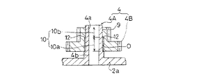
図8及び図9は本発明の実施の一形態であるディスクプレーヤーの動力伝達機構4を示すものであって、歯車4Bの内周面10の上端に環状凹段部13が形成され、その環状凹段部13に嵌合して内周面15aを支軸4Aの外周面9に接近させたリング状油漏れ防止キャップ15が設けられている。上記以外の構成は第2の参考例とほぼ同じであるから、同一部分に同一符号を付してその説明を省略する。
【0021】
上記構成によれば、油漏れ防止キャップ15により油溜溝12の上端開口部が塞がれるので、歯車4Bの回転による遠心力で油溜溝12内のグリスなどの潤滑油Oが上方へ流出するのを防止することができる。
【0022】
【発明の効果】
請求項1記載の発明によれば、歯車の内周面に形成した油溜溝にグリスなどの潤滑油を供給することにより、その歯車を長期にわたって円滑に回転させることができる。
【0023】
また、油溜溝が歯車の内周面に周方向所定間隔をおいて複数形成されているので、その各油溜溝から潤滑油を支軸の外周面にほぼ均等に供給することができる
。
【0024】
更に、歯車に設けた溝無し面を支軸の外周面に対向させているので、その歯車の回転を安定させることができ、これによって、歯車に設けた溝付き面の油溜溝により該歯車の回転が不安定になるのを防ぐことができる。
【0025】
また更に、歯車の内周面上端の環状凹段部に嵌合する油漏れ防止キャップより
油溜溝の上端開口部が塞がれるので、歯車の回転による遠心力で油溜溝内のグリスなどの潤滑油が上方へ流出するのを防止することができる。
【0026】
しかも、油溜溝に充填したグリスなどの潤滑油によって歯車を長期にわたって円滑に回転させることができるようにしたディスクプレーヤーを提供することができる。
【図面の簡単な説明】
【図1】本発明の第1の参考例であるディスクプレーヤーの動力伝達機構を示す縦断面図である。
【図2】同横断面図である。
【図3】同分解斜視図である。
【図4】本発明の第2の参考例であるディスクプレーヤーの動力伝達機構を示す縦断面図である。
【図5】同横断面図である。
【図6】同分解斜視図である。
【図7】本発明の第3の参考例であるディスクプレーヤーの動力伝達機構を示す縦断面図である。
【図8】本発明の実施の一形態であるディスクプレーヤーの動力伝達機構を示す縦断面図である。
【図9】同分解斜視図である。
【図10】ディスクプレーヤーを示す斜視図である。
【図11】同横断面図である。
【図12】従来の動力伝達機構を示す縦断面図である。
【図13】同水平断面図である。
【符号の説明】
1 トレー(被駆動部)
3 光ピックアップ(被駆動部)
4 動力伝達機構
4A 支軸
4B 歯車
5 駆動モータ
9 支軸の小径部外周面
10 歯車の内周面
10a 溝付き面
10b 溝無し面
12 油溜溝
13 環状凹段部
15 油漏れ防止キャップ
O 潤滑油[0001]
TECHNICAL FIELD OF THE INVENTION
The present invention relates to a drive motor for an electronic device such as a disk player for reproducing, recording, or erasing information recorded on an optical disk, which is abbreviated as a CD or a DVD, or a magneto-optical disk (hereinafter, referred to as a disk). The present invention relates to a power transmission mechanism for transmitting power to a driven part.
[0002]
[Prior art]
10 and 11 show an example of a disc player. This is because the tray 1 supporting the disk D is provided on the
[0003]
In the above configuration, after the disc D is placed on the tray 1 that has been advanced a (see the phantom line in FIG. 10), the tray 1 is retracted b by the drive motor 5 via the power transmission mechanism 4 (see the solid line in FIG. 10). Next, the optical pickup 3 is raised by the drive motor 5 via the
[0004]
Conventionally, in order to smoothly rotate each
[0005]
[Problems to be solved by the invention]
In the above-mentioned conventional configuration, only the grease is filled between the small-diameter portion outer
[0006]
According to Japanese Utility Model Application Laid-Open No. Sho 62-166358, grooves are formed at predetermined intervals in the circumferential direction on the outer
[0007]
An object of the present invention is to provide a power transmission mechanism of an electronic device capable of rotating a gear smoothly for a long period of time in view of the above-mentioned conventional drawbacks.
[0008]
[Means for Solving the Problems]
In order to achieve the above object, an invention according to claim 1 is a power transmission mechanism for transmitting power from a drive motor of a disk player to a driven portion, wherein the power transmission mechanism comprises a support shaft, and a rotatable outer shaft. Having a gear fitted therein, the inner peripheral surface of the gear having a grooved surface having a plurality of oil reservoir grooves formed at predetermined circumferential intervals, and a grooveless surface having no oil reservoir groove formed therein. An annular concave step is formed at the upper end of the inner peripheral surface of the gear, and the outer diameter of the annular concave step is larger than the outer diameter of an imaginary circle connecting the outer peripheral edges of the oil reservoir grooves. By setting, the upper end opening of each oil reservoir groove is opened from the center of the bottom surface of the annular concave step to the inner peripheral edge, and the inner peripheral surface is fitted to the annular concave step and the outer peripheral surface of the support shaft. this ring-shaped oil leakage prevention cap for closing the upper end opening of the oil reservoir groove by close to the surface are provided It is characterized in.
[0009]
According to the above configuration, by supplying lubricating oil such as grease to the oil reservoir formed on the inner peripheral surface of the gear, the gear can be smoothly rotated for a long time.
[0010]
Further, since a plurality of oil reservoir grooves are formed on the inner peripheral surface of the gear at predetermined intervals in the circumferential direction, lubricating oil can be supplied from the respective oil reservoir grooves to the outer peripheral surface of the support shaft almost uniformly.
[0011]
Furthermore, since the non-grooved surface provided on the gear is opposed to the outer peripheral surface of the support shaft, the rotation of the gear can be stabilized, whereby the oil storage groove of the grooved surface provided on the gear allows the gear to be rotated. Can be prevented from becoming unstable.
[0012]
Further, since the upper end opening of the oil reservoir groove is closed by the oil leakage prevention cap fitted to the annular concave step at the upper end of the inner peripheral surface of the gear, the grease in the oil reservoir groove is centrifugally generated by the rotation of the gear. Of the lubricating oil can be prevented from flowing upward.
[0013]
Moreover, it is possible to provide a disk player in which the gear can be smoothly rotated for a long period of time by lubricating oil such as grease filled in the oil reservoir groove.
[0014]
BEST MODE FOR CARRYING OUT THE INVENTION
Hereinafter, embodiments of the present invention will be described with reference to the drawings. 1 to 3 there is shown a first
[0015]
According to the above configuration, by filling the
[0016]
4 to 6, there is shown a second reference example
[0017]
According to the above configuration, since the
[0018]
FIG. 7 shows a
[0019]
According to the above configuration, similarly to the second reference example , the rotation of the
[0020]
FIGS. 8 and 9 show a
[0021]
According to the above configuration, since the upper end opening of the
[0022]
【The invention's effect】
According to the first aspect of the present invention, by supplying lubricating oil such as grease to the oil reservoir formed on the inner peripheral surface of the gear, the gear can be smoothly rotated for a long period of time.
[0023]
Further, since a plurality of oil reservoir grooves are formed on the inner peripheral surface of the gear at predetermined intervals in the circumferential direction, lubricating oil can be supplied from the respective oil reservoir grooves to the outer peripheral surface of the support shaft almost uniformly.
[0024]
Furthermore, since the non-grooved surface provided on the gear is opposed to the outer peripheral surface of the support shaft, the rotation of the gear can be stabilized, whereby the oil storage groove of the grooved surface provided on the gear allows the gear to be rotated. Can be prevented from becoming unstable.
[0025]
Further, since the upper end opening of the oil reservoir groove is closed by the oil leakage prevention cap fitted to the annular concave step at the upper end of the inner peripheral surface of the gear, the grease in the oil reservoir groove is centrifugally generated by the rotation of the gear. Of the lubricating oil can be prevented from flowing upward.
[0026]
Moreover, it is possible to provide a disk player in which the gear can be smoothly rotated for a long time by lubricating oil such as grease filled in the oil reservoir groove.
[Brief description of the drawings]
FIG. 1 is a longitudinal sectional view showing a power transmission mechanism of a disc player according to a first reference example of the present invention.
FIG. 2 is a cross-sectional view of the same.
FIG. 3 is an exploded perspective view of the same.
FIG. 4 is a longitudinal sectional view showing a power transmission mechanism of a disc player according to a second reference example of the present invention.
FIG. 5 is a transverse sectional view of the same.
FIG. 6 is an exploded perspective view of the same.
FIG. 7 is a longitudinal sectional view showing a power transmission mechanism of a disc player according to a third reference example of the present invention.
FIG. 8 is a longitudinal sectional view showing a power transmission mechanism of the disc player according to one embodiment of the present invention.
FIG. 9 is an exploded perspective view of the same.
FIG. 10 is a perspective view showing a disc player.
FIG. 11 is a transverse sectional view of the same.
FIG. 12 is a longitudinal sectional view showing a conventional power transmission mechanism.
FIG. 13 is a horizontal sectional view of the same.
[Explanation of symbols]
1 tray (driven part)
3 Optical pickup (driven part)
Claims (1)
Priority Applications (1)
| Application Number | Priority Date | Filing Date | Title |
|---|---|---|---|
| JP01095799A JP3558207B2 (en) | 1999-01-19 | 1999-01-19 | Power transmission mechanism for electronic equipment |
Applications Claiming Priority (1)
| Application Number | Priority Date | Filing Date | Title |
|---|---|---|---|
| JP01095799A JP3558207B2 (en) | 1999-01-19 | 1999-01-19 | Power transmission mechanism for electronic equipment |
Publications (2)
| Publication Number | Publication Date |
|---|---|
| JP2000205383A JP2000205383A (en) | 2000-07-25 |
| JP3558207B2 true JP3558207B2 (en) | 2004-08-25 |
Family
ID=11764677
Family Applications (1)
| Application Number | Title | Priority Date | Filing Date |
|---|---|---|---|
| JP01095799A Expired - Fee Related JP3558207B2 (en) | 1999-01-19 | 1999-01-19 | Power transmission mechanism for electronic equipment |
Country Status (1)
| Country | Link |
|---|---|
| JP (1) | JP3558207B2 (en) |
Families Citing this family (2)
| Publication number | Priority date | Publication date | Assignee | Title |
|---|---|---|---|---|
| JP6388197B2 (en) * | 2014-06-23 | 2018-09-12 | 株式会社リコー | Drive transmission device and image forming apparatus |
| JP6537229B2 (en) | 2014-07-31 | 2019-07-03 | キヤノン株式会社 | Drive transmission mechanism and image forming apparatus |
-
1999
- 1999-01-19 JP JP01095799A patent/JP3558207B2/en not_active Expired - Fee Related
Also Published As
| Publication number | Publication date |
|---|---|
| JP2000205383A (en) | 2000-07-25 |
Similar Documents
| Publication | Publication Date | Title |
|---|---|---|
| CN102355081B (en) | Spindle motor and storage disk drive apparatus | |
| KR100716905B1 (en) | Spindle motor | |
| JP2004183865A (en) | Fluid bearing and disk drive | |
| JP2844531B2 (en) | Rotation control damper | |
| JP3558207B2 (en) | Power transmission mechanism for electronic equipment | |
| JP3503813B2 (en) | Power transmission mechanism for electronic equipment | |
| KR100263890B1 (en) | Optical disk integrated with self-compensating dynamic balancer | |
| JP2005009580A (en) | Hydrodynamic bearing apparatus and disk apparatus | |
| KR200150905Y1 (en) | Disk changer device | |
| KR100785797B1 (en) | Optical disk drive adapter | |
| JP2007280463A (en) | Optical disk device | |
| JPH0668872B2 (en) | Magnetic recording / reproducing device | |
| KR100587846B1 (en) | Automatic Centering Apparatus Of Disc | |
| US20030174439A1 (en) | Low power spindle motor with a fluid dynamic spool bearing | |
| KR20020064445A (en) | Disk drive and disk cartridge | |
| JPH08185629A (en) | Optical disk and optical disk device | |
| KR100569495B1 (en) | Pickup unit of a optical disk player | |
| KR100288914B1 (en) | Cartridge of information recording/reproducing medium | |
| KR0170120B1 (en) | Head drum assembly | |
| US20080117792A1 (en) | Three-dimensional storage medium | |
| KR100518585B1 (en) | Optic disc drive | |
| WO1999016066A1 (en) | Cd changer | |
| JPH10288223A (en) | Dynamic pressure fluid bearing and disc device using the bearing | |
| JPH10281143A (en) | Spindle motor for dynamic pressure bearing | |
| JP2006344267A (en) | Cartridge case and information recording medium |
Legal Events
| Date | Code | Title | Description |
|---|---|---|---|
| A131 | Notification of reasons for refusal |
Free format text: JAPANESE INTERMEDIATE CODE: A131 Effective date: 20040130 |
|
| A521 | Written amendment |
Free format text: JAPANESE INTERMEDIATE CODE: A523 Effective date: 20040317 |
|
| TRDD | Decision of grant or rejection written | ||
| A01 | Written decision to grant a patent or to grant a registration (utility model) |
Free format text: JAPANESE INTERMEDIATE CODE: A01 Effective date: 20040430 |
|
| A61 | First payment of annual fees (during grant procedure) |
Free format text: JAPANESE INTERMEDIATE CODE: A61 Effective date: 20040513 |
|
| R150 | Certificate of patent or registration of utility model |
Free format text: JAPANESE INTERMEDIATE CODE: R150 |
|
| R250 | Receipt of annual fees |
Free format text: JAPANESE INTERMEDIATE CODE: R250 |
|
| FPAY | Renewal fee payment (event date is renewal date of database) |
Free format text: PAYMENT UNTIL: 20080528 Year of fee payment: 4 |
|
| FPAY | Renewal fee payment (event date is renewal date of database) |
Free format text: PAYMENT UNTIL: 20090528 Year of fee payment: 5 |
|
| FPAY | Renewal fee payment (event date is renewal date of database) |
Free format text: PAYMENT UNTIL: 20090528 Year of fee payment: 5 |
|
| FPAY | Renewal fee payment (event date is renewal date of database) |
Free format text: PAYMENT UNTIL: 20100528 Year of fee payment: 6 |
|
| FPAY | Renewal fee payment (event date is renewal date of database) |
Free format text: PAYMENT UNTIL: 20100528 Year of fee payment: 6 |
|
| FPAY | Renewal fee payment (event date is renewal date of database) |
Free format text: PAYMENT UNTIL: 20110528 Year of fee payment: 7 |
|
| FPAY | Renewal fee payment (event date is renewal date of database) |
Free format text: PAYMENT UNTIL: 20110528 Year of fee payment: 7 |
|
| FPAY | Renewal fee payment (event date is renewal date of database) |
Free format text: PAYMENT UNTIL: 20120528 Year of fee payment: 8 |
|
| FPAY | Renewal fee payment (event date is renewal date of database) |
Free format text: PAYMENT UNTIL: 20120528 Year of fee payment: 8 |
|
| FPAY | Renewal fee payment (event date is renewal date of database) |
Free format text: PAYMENT UNTIL: 20130528 Year of fee payment: 9 |
|
| FPAY | Renewal fee payment (event date is renewal date of database) |
Free format text: PAYMENT UNTIL: 20130528 Year of fee payment: 9 |
|
| FPAY | Renewal fee payment (event date is renewal date of database) |
Free format text: PAYMENT UNTIL: 20140528 Year of fee payment: 10 |
|
| LAPS | Cancellation because of no payment of annual fees |