JP3557764B2 - Axle housing - Google Patents
Axle housing Download PDFInfo
- Publication number
- JP3557764B2 JP3557764B2 JP01491596A JP1491596A JP3557764B2 JP 3557764 B2 JP3557764 B2 JP 3557764B2 JP 01491596 A JP01491596 A JP 01491596A JP 1491596 A JP1491596 A JP 1491596A JP 3557764 B2 JP3557764 B2 JP 3557764B2
- Authority
- JP
- Japan
- Prior art keywords
- housing
- housing portion
- center
- center housing
- axle
- Prior art date
- Legal status (The legal status is an assumption and is not a legal conclusion. Google has not performed a legal analysis and makes no representation as to the accuracy of the status listed.)
- Expired - Fee Related
Links
Images


Description
【0001】
【発明の属する技術分野】
本発明は、四輪車用のアクスルハウジングに関するものである。
【0002】
【従来の技術】
一般に、自動車用リジッドアクスル式サスペンションの駆動車軸に適用されるアクスルハウジングには、例えば図8〜図10に示すようなものがある。このアクスルハウジング51は、上下一対のセンタハウジング部52,53、左右一対のチューブハウジング部54,55およびバッキングチューブ56等を有しており、これら各部材は溶接によって互いに接合されている。しかして、センタハウジング部52,53のデフ収納部57内にはディファレンシャルギヤ58が配置され、チューブハウジング部54,55内には図示しないアクスルシャフトが挿入されるとともに、センタハウジング部52,53にはデフオイル59が注油されている。
【0003】
【発明が解決しようとする課題】
ところが、上述した従来のアクスルハウジング51では、センタハウジング部52,53とチューブハウジング部54,55との接合部などが応力集中部となるので、補強部材60を使用することによって強度確保を図る必要があった。また、従来のアクスルハウジング51では、自動車走行中の横加速度や路面の傾斜などによってデフオイル59がディファレンシャルギヤ58の付近から流出するので、これを防ぐオイルデフレクタプレート61やオイルデフレクタ62が必要であった。したがって、従来のアクスルハウジング51では、多くの部品を用いる必要があることから、部品点数が増えてコスト高を招くおそれがあった。
【0004】
一方、上記オイルデフレクタプレート61は、図10に示す如く、センタハウジング部52,53のデフ収納部57内に立設されているので、矢印に示すように、デフオイル59の外方への流出がオイルデフレクタプレート61により抑制されるが、いったん流出したデフオイル59はオイルデフレクタプレート61によりデフ収納部57内に戻りにくいという不具合を有していた。
【0005】
本発明はこのような実状に鑑みてなされたものであって、その目的は、簡単な構造で高強度・高機能を得ることができ、かつ部品点数の削減によってコストダウンを図ることが可能なアクスルハウジングを提供することにある。
【0006】
【課題を解決するための手段】
上記従来技術の有する課題を解決するために、本発明においては、少なくともセンタハウジング部と左右一対のチューブハウジング部とを互いに接合することにより構成されるアクスルハウジングにおいて、上記センタハウジング部を分割構造とし、上記左右一対のチューブハウジング部のセンタハウジング部側端部を延長して上記センタハウジング部のデフ収納部形状に拡大成形し、該拡大成形したチューブハウジング部の延長部を上記センタハウジング部の内部に入れ、下部側先端を除いて上記センタハウジング部に重なり合わせて接合させ、上記チューブハウジング部の一部を、上記センタハウジング部の底面から所定の高さ位置に配設される横方向の壁であるバッフルプレートとして構成している。
また、本発明においては、少なくともセンタハウジング部と左右一対のチューブハウジング部とを互いに接合することにより構成されるアクスルハウジングにおいて、上記センタハウジング部を分割構造とし、上記チューブハウジング部側に位置する基端部を上記センタハウジング部に接合し、先端部を上記センタハウジング部内に突出して上記センタハウジング部の底面から所定の高さ位置に配設される横方向の壁であるバッフルプレート構造を持つ補強部材を配置している。
さらに、本発明においては、少なくともセンタハウジング部と左右一対のチューブハウジング部とを互いに接合することにより構成されるアクスルハウジングにおいて、上記センタハウジング部を分割構造とし、上記センタハウジング部側が拡大成形された筒状体の下端側先端部を上記センタハウジング部内に突出して上記センタハウジング部の底面から所定の高さ位置に配設される横方向の壁であるバッフルプレート構造を持つ補強部材を配置している。
【0007】
【発明の実施の形態】
以下、本発明を図示の実施の形態に基づいて詳細に説明する。
【0008】
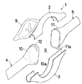
図1〜図3は、本発明に係るアクスルハウジングの実施の形態を示している。図において、1は本実施の形態の四輪車用アクスルハウジングであり、このアクスルハウジング1は、2分割構造とされた上下一対のセンタハウジング部2,3と、これらセンタハウジング部2,3の左右両端に配設される左右一対のチューブハウジング部4,5とを備えており、センタハウジング部2,3とチューブハウジング部4,5とを溶接にて互いに接合することにより構成されている。
【0009】
上記センタハウジング部2,3は、相互に向き合って配置される正面略半円弧状体であり、これらセンタハウジング部2,3を上下方向から合わせて配設することにより、デフ収納部6がアクスルハウジング1の内部に形成されるようになっている。このデフ収納部6内には、ディファレンシャルギヤ7が回転自在に配置されているとともに、デフオイル8が注油されている。なお、図1において、9はカバーである。
【0010】
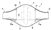
一方、上記チューブハウジング部4,5は、図示しないアクスルシャフトを内挿することが可能な管状体であり、それぞれのセンタハウジング部2,3側に位置する端部には、これをデフ収納部6内に向かって延長した延長部10,11が軸心方向に沿って設けられている。しかも、これら延長部10,11は、センタハウジング部2,3のデフ収納部6の形状に対応すべく拡大成形されており、拡大成形された延長部10,11は下部側先端を除いてセンタハウジング部2,3に重なり合わせられた状態で、当該重合部が溶接により接合されるように構成されている。したがって、アクスルハウジング1は、応力集中部となるセンタハウジング部2,3とチューブハウジング部4,5との接合部が広い範囲にわたって2重構造となっている。
【0011】
また、上記チューブハウジング部4,5の延長部10,11の下部側は、センタハウジング部2,3の内部に入れられ、これによってチューブハウジング部4,5の一部がバッフルプレート10a,11aとして構成されている。これらバッフルプレート10a,11aは、センタハウジング部3の底面から所定の高さ位置に配設される横方向の壁であり、自動車走行中の横加速度負荷時や路面傾斜時にもデフ収納部6内にデフオイル8が残存するようになっている。すなわち、バッフルプレート10a,11aによって、デフ収納部6からデフオイル8の流出が抑制され、それと同時に側方に流出したデフオイル8がディファレンシャルギヤ7付近に戻り易くなっている。
【0012】
さらに、一方のチューブハウジング部4の延長部10の上面部には、巾方向に沿って延びる凹部12が形成されており、この凹部12はブリーザプラグ13と対応して配設されている。このため、ブリーザプラグ13の取付箇所は、延長部10の凹部12によって覆われ、ブリーザプラグ13からのオイル飛沫の流出が防止できる構造となっている。
【0013】
なお、チューブハウジング部4,5の製法としては、パイプ材の端部拡管又はスウェィジング、液圧バルジ加工後に切断し、プレス品(上下分割)の溶接等が考えられる。
【0014】
本実施の形態のアクスルハウジング1では、チューブハウジング部4,5のセンタハウジング部2,3側に特殊な形状の延長部10,11を形成し、応力集中部となるセンタハウジング部2,3とチューブハウジング部4,5との接合部を広い範囲で2重構造としているため、従来のアクスルハウジングに必要であった補強部材が不要となった。また、延長部10,11の下部側は、従来において縦方向の壁を設置していたのに変えて、所定の高さ位置に配設された横方向の壁とするバッフルプレート10a,11aとして構成されているため、従来のアクスルハウジングに必要であったオイルデフレクタを廃止できて簡単な構造が得られ、しかも、図3の矢印に示す如く、デフオイル8の流出を抑制するのと同時にチューブハウジング部4,5へ流出したデフオイル8を円滑に戻すことが可能となった。
【0015】
以上、本発明の実施の形態につき述べたが、本発明は既述の実施の形態に限定されるものではなく、本発明の技術的思想に基づいて各種の変形および変更が可能である。
【0016】
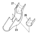
例えば、図4および図5に示すようなアクスルハウジング21は、センタハウジング部22,23とチューブハウジング部24,25を従来構造とし、既述の実施の形態と異なり、半円筒状体の補強部材26,27を用いている。そして、これら補強部材26,27のチューブハウジング部24,25側に位置する基端部26a,27aをセンタハウジング部23に接合し、補強部材26,27の先端部26b,27bをセンタハウジング部22,23内に突出すべく配置して、オイル流出抑制のバッフルプレートとして用いている。したがって、この変形例によれば、補強部材26,27がバッフルプレートとしての機能も有しているため、従来のアクスルハウジングで使用したオイルデフレクタプレートは不要となる。
【0017】
また、図6および図7に示すようなアクスルハウジング31は、上記変形例と同様、センタハウジング部22,23とチューブハウジング部24,25を従来構造とし、既述の実施の形態と異なり、センタハウジング部22,23側が拡大成形された円筒状体の補強部材36を用いている。そして、下部側先端部36aを除いて、当該補強部材36をチューブハウジング部25およびセンタハウジング部22,23に接合し、その下部側先端部36aをセンタハウジング部22,23内に突出すべく配置して、オイル流出抑制のバッフルプレートとして用いている。また、補強部材36の上面部には、巾方向に沿って延びる凹部37が形成されており、この凹部37はブリーザプラグ38と対応して配設され、該ブリーザプラグ38からのオイル飛沫の流出を防止している。したがって、この変形例によれば、補強部材36がバッフルプレート等としての機能も有しているため、従来のアクスルハウジングで使用したオイルデフレクタプレートおよびオイルデフレクタは不要となる。
【0018】
【発明の効果】
上述の如く、本発明に係るアクスルハウジングは、少なくともセンタハウジング部と左右一対のチューブハウジング部とを互いに接合することにより構成されるものであって、上記センタハウジング部を分割構造とし、上記左右一対のチューブハウジング部のセンタハウジング部側端部を延長して上記センタハウジング部のデフ収納部形状に拡大成形し、該拡大成形したチューブハウジング部の延長部を上記センタハウジング部の内部に入れ、下部側先端を除いて上記センタハウジング部に重なり合わせて接合させ、上記チューブハウジング部の一部を、上記センタハウジング部の底面から所定の高さ位置に配設される横方向の壁であるバッフルプレートとして構成しているので、従来のアクスルハウジングと比べてハウジング構造が簡単である上、応力集中部となるセンタハウジング部とチューブハウジング部との接合部などを補強でき、高強度・高機能を確保することができる。しかも、本発明のアクスルハウジングでは、補強部材やオイルデフレクタ等を使用する必要がなくなるので、部品点数および組付工数の削減によってコストダウンを図ることができる。
また、本発明に係るアクスルハウジングは、少なくともセンタハウジング部と左右一対のチューブハウジング部とを互いに接合することにより構成されるものであって、上記センタハウジング部を分割構造とし、上記チューブハウジング部側に位置する基端部を上記センタハウジング部に接合し、先端部を上記センタハウジング部内に突出して上記センタハウジング部の底面から所定の高さ位置に配設される横方向の壁であるバッフルプレート構造を持つ補強部材を配置しているので、従来のアクスルハウジングと比べてハウジング構造が簡単である上、応力集中部となるセンタハウジング部とチューブハウジング部との接合部などをより一層補強でき、高強度・高機能を確保することができる。しかも、本発明のアクスルハウジングでは、オイルデフレクタ等を使用する必要がなくなるので、部品点数および組付工数の削減によってコストダウンを図ることができる。
さらに、本発明に係るアクスルハウジングは、少なくともセンタハウジング部と左右一対のチューブハウジング部とを互いに接合することにより構成されるものであって、上記センタハウジング部を分割構造とし、上記センタハウジング部側が拡大成形された筒状体の下端側先端部を上記センタハウジング部内に突出して上記センタハウジング部の底面から所定の高さ位置に配設される横方向の壁であるバッフルプレート構造を持つ補強部材を配置しているので、上記発明と同様の効果が得られる。
【図面の簡単な説明】
【図1】本発明の実施の形態に係るアクスルハウジングを分解して示す斜視図である。
【図2】本発明の実施の形態のアクスルハウジングを示す正面図である。
【図3】センタハウジング部の内部にデフオイルが注油された本発明の実施の形態のアクスルハウジングを示す断面図である。
【図4】本実施の形態の変形例に係るアクスルハウジングを示す断面図である。
【図5】図4におけるアクスルハウジングのセンタハウジング部と補強部材との関係を示す斜視図である。
【図6】本実施の形態の他の変形例に係るアクスルハウジングを示す断面図である。
【図7】図6におけるアクスルハウジングのセンタハウジング部と補強部材との関係を示す斜視図である。
【図8】従来のアクスルハウジングを分解して示す斜視図である。
【図9】従来のアクスルハウジングを示す正面図である。
【図10】センタハウジング部の内部にデフオイルが注油された従来のアクスルハウジングを示す断面図である。
【符号の説明】
1 アクスルハウジング
2,3 センタハウジング部
4,5 チューブハウジング
6 デフ収納部
10,11 延長部[0001]
TECHNICAL FIELD OF THE INVENTION
The present invention relates to an axle housing for a four-wheeled vehicle.
[0002]
[Prior art]
Generally, there is an axle housing applied to a drive axle of a rigid axle suspension for an automobile, for example, as shown in FIGS. The
[0003]
[Problems to be solved by the invention]
However, in the
[0004]
On the other hand, the
[0005]
The present invention has been made in view of such circumstances, and an object of the present invention is to achieve high strength and high function with a simple structure and reduce costs by reducing the number of parts. An axle housing is provided.
[0006]
[Means for Solving the Problems]
In order to solve the problems of the prior art, according to the present invention, in an axle housing configured by joining at least a center housing portion and a pair of left and right tube housing portions to each other, the center housing portion has a divided structure. The end of the pair of left and right tube housings on the side of the center housing is extended so as to be enlarged into the shape of the differential housing portion of the center housing, and the extended portion of the enlarged tube housing is inserted into the center housing. The center housing portion is overlapped and joined except for the lower end, and a part of the tube housing portion is disposed at a predetermined height from the bottom surface of the center housing portion in a lateral wall. It is configured as a baffle plate .
Further, in the present invention, in the axle housing configured by joining at least a center housing portion and a pair of left and right tube housing portions to each other, the center housing portion has a divided structure, and a base located on the tube housing portion side. A reinforcement having a baffle plate structure, which is a lateral wall disposed at a predetermined height from a bottom surface of the center housing portion by projecting an end portion into the center housing portion and projecting a front end portion into the center housing portion. The members are arranged.
Further, in the present invention, in the axle housing configured by joining at least the center housing part and the pair of left and right tube housing parts to each other, the center housing part is divided and the center housing part side is enlarged and formed. A reinforcing member having a baffle plate structure that is a lateral wall disposed at a predetermined height from the bottom surface of the center housing portion by projecting a lower end side tip portion of the cylindrical body into the center housing portion is disposed. I have.
[0007]
BEST MODE FOR CARRYING OUT THE INVENTION
Hereinafter, the present invention will be described in detail based on illustrated embodiments.
[0008]
1 to 3 show an embodiment of an axle housing according to the present invention. In the drawings,
[0009]
The
[0010]
On the other hand, the
[0011]
The lower portions of the
[0012]
Further, a
[0013]
In addition, as a manufacturing method of the
[0014]
In the
[0015]
Although the embodiments of the present invention have been described above, the present invention is not limited to the above-described embodiments, and various modifications and changes can be made based on the technical idea of the present invention.
[0016]
For example, an
[0017]
An
[0018]
【The invention's effect】
As described above, the axle housing according to the present invention is configured by joining at least a center housing portion and a pair of left and right tube housing portions to each other, and the center housing portion has a divided structure, The end of the tube housing portion on the side of the center housing portion is extended to be enlarged and formed into the shape of the differential housing portion of the center housing portion, and the extended portion of the enlarged tube housing portion is inserted into the center housing portion, and A baffle plate, which is a lateral wall disposed at a predetermined height from the bottom surface of the center housing part, and a part of the tube housing part is overlapped and joined to the center housing part except for a side end. since the configuration as the housing structure is simple compared to conventional axle housing That on, such as the junction of the center housing and tubing housing portion serving as a stress concentration portion can be reinforced, it is possible to secure a high strength and high performance. Moreover, in the axle housing of the present invention, since it is not necessary to use a reinforcing member, an oil deflector, or the like, the cost can be reduced by reducing the number of parts and the number of assembling steps.
Further, the axle housing according to the present invention is configured by joining at least a center housing portion and a pair of left and right tube housing portions to each other, and the center housing portion has a divided structure, and the tube housing portion side A baffle plate which is a lateral wall which is joined to the center housing portion at a predetermined position, and a distal end portion projects into the center housing portion and is disposed at a predetermined height from the bottom surface of the center housing portion. Since the reinforcing member with the structure is arranged, the housing structure is simpler than the conventional axle housing, and the joint between the center housing and the tube housing, which are stress concentration parts, can be further reinforced. High strength and high function can be secured. Moreover, in the axle housing of the present invention, it is not necessary to use an oil deflector or the like, so that the cost can be reduced by reducing the number of parts and the number of assembling steps.
Further, the axle housing according to the present invention is configured by joining at least a center housing portion and a pair of left and right tube housing portions to each other. The center housing portion has a divided structure, and the center housing portion side has A reinforcing member having a baffle plate structure, which is a lateral wall disposed at a predetermined height from a bottom surface of the center housing portion by projecting a lower end side distal end of the enlarged cylindrical body into the center housing portion. Are arranged, the same effect as the above invention can be obtained.
[Brief description of the drawings]
FIG. 1 is an exploded perspective view showing an axle housing according to an embodiment of the present invention.
FIG. 2 is a front view showing the axle housing according to the embodiment of the present invention.
FIG. 3 is a cross-sectional view showing an axle housing according to an embodiment of the present invention in which a differential oil is injected into a center housing portion.
FIG. 4 is a sectional view showing an axle housing according to a modification of the present embodiment.
FIG. 5 is a perspective view showing a relationship between a center housing portion of the axle housing and a reinforcing member in FIG.
FIG. 6 is a cross-sectional view showing an axle housing according to another modification of the present embodiment.
FIG. 7 is a perspective view showing a relationship between a center housing portion of the axle housing and a reinforcing member in FIG.
FIG. 8 is an exploded perspective view showing a conventional axle housing.
FIG. 9 is a front view showing a conventional axle housing.
FIG. 10 is a cross-sectional view showing a conventional axle housing in which differential oil is injected into a center housing portion.
[Explanation of symbols]
1
Claims (5)
Priority Applications (1)
| Application Number | Priority Date | Filing Date | Title |
|---|---|---|---|
| JP01491596A JP3557764B2 (en) | 1996-01-31 | 1996-01-31 | Axle housing |
Applications Claiming Priority (1)
| Application Number | Priority Date | Filing Date | Title |
|---|---|---|---|
| JP01491596A JP3557764B2 (en) | 1996-01-31 | 1996-01-31 | Axle housing |
Publications (2)
| Publication Number | Publication Date |
|---|---|
| JPH09207506A JPH09207506A (en) | 1997-08-12 |
| JP3557764B2 true JP3557764B2 (en) | 2004-08-25 |
Family
ID=11874270
Family Applications (1)
| Application Number | Title | Priority Date | Filing Date |
|---|---|---|---|
| JP01491596A Expired - Fee Related JP3557764B2 (en) | 1996-01-31 | 1996-01-31 | Axle housing |
Country Status (1)
| Country | Link |
|---|---|
| JP (1) | JP3557764B2 (en) |
Families Citing this family (4)
| Publication number | Priority date | Publication date | Assignee | Title |
|---|---|---|---|---|
| JP5270193B2 (en) * | 2008-02-29 | 2013-08-21 | プレス工業株式会社 | Axle case |
| CN104442197B (en) * | 2013-09-18 | 2017-03-15 | 比亚迪股份有限公司 | Axle housing component for vehicle and the vehicle with it |
| CN104816585B (en) * | 2015-03-10 | 2016-10-05 | 盐城工学院 | Split type axle housing automobile drive axle |
| CN107415587A (en) * | 2016-05-24 | 2017-12-01 | 吴富强 | A kind of automobile rear axle housing |
-
1996
- 1996-01-31 JP JP01491596A patent/JP3557764B2/en not_active Expired - Fee Related
Also Published As
| Publication number | Publication date |
|---|---|
| JPH09207506A (en) | 1997-08-12 |
Similar Documents
| Publication | Publication Date | Title |
|---|---|---|
| JP3994202B2 (en) | Modular chassis for automobiles | |
| US5562308A (en) | Subframe structure in motor vehicle | |
| JPS6017414Y2 (en) | Joint structure of automobile front deck | |
| US6494472B2 (en) | Suspension frame construction | |
| AU7256300A (en) | Steering gear frame | |
| US5542707A (en) | Subframe assembly for vehicle | |
| JPH02200586A (en) | Oil tank device for motorcycle | |
| JP2003182626A (en) | Suspension supporting structure | |
| JP3557764B2 (en) | Axle housing | |
| JP3354300B2 (en) | Subframe structure in automobile | |
| JP4249331B2 (en) | Motorcycle body frame | |
| JP3214783B2 (en) | Fuel tank support structure | |
| JP2001180297A (en) | Engine mounting bracket | |
| JPH0513669Y2 (en) | ||
| JP2500897Y2 (en) | Automotive trunnion shaft | |
| JP2549490B2 (en) | Rear frame of wheel crane and manufacturing method thereof | |
| JPH07246464A (en) | Structural member | |
| JPH0625414Y2 (en) | Front body joint structure for automobile | |
| JP3476101B2 (en) | Vehicle subframe | |
| JP3592137B2 (en) | Spring support coupling structure | |
| JPH0439968U (en) | ||
| JP2875994B2 (en) | Cowl side structure | |
| JPH0518233Y2 (en) | ||
| JPH0528787U (en) | Front body structure of automobile | |
| JPH0134628Y2 (en) |
Legal Events
| Date | Code | Title | Description |
|---|---|---|---|
| A131 | Notification of reasons for refusal |
Free format text: JAPANESE INTERMEDIATE CODE: A131 Effective date: 20040106 |
|
| A521 | Written amendment |
Free format text: JAPANESE INTERMEDIATE CODE: A523 Effective date: 20040302 |
|
| TRDD | Decision of grant or rejection written | ||
| A01 | Written decision to grant a patent or to grant a registration (utility model) |
Free format text: JAPANESE INTERMEDIATE CODE: A01 Effective date: 20040427 |
|
| A61 | First payment of annual fees (during grant procedure) |
Free format text: JAPANESE INTERMEDIATE CODE: A61 Effective date: 20040510 |
|
| LAPS | Cancellation because of no payment of annual fees |