JP3557063B2 - Non-sintered nickel electrode for alkaline storage batteries - Google Patents
Non-sintered nickel electrode for alkaline storage batteries Download PDFInfo
- Publication number
- JP3557063B2 JP3557063B2 JP00326997A JP326997A JP3557063B2 JP 3557063 B2 JP3557063 B2 JP 3557063B2 JP 00326997 A JP00326997 A JP 00326997A JP 326997 A JP326997 A JP 326997A JP 3557063 B2 JP3557063 B2 JP 3557063B2
- Authority
- JP
- Japan
- Prior art keywords
- alkaline storage
- storage battery
- active material
- positive electrode
- yttrium
- Prior art date
- Legal status (The legal status is an assumption and is not a legal conclusion. Google has not performed a legal analysis and makes no representation as to the accuracy of the status listed.)
- Expired - Lifetime
Links
Images

Classifications
-
- Y—GENERAL TAGGING OF NEW TECHNOLOGICAL DEVELOPMENTS; GENERAL TAGGING OF CROSS-SECTIONAL TECHNOLOGIES SPANNING OVER SEVERAL SECTIONS OF THE IPC; TECHNICAL SUBJECTS COVERED BY FORMER USPC CROSS-REFERENCE ART COLLECTIONS [XRACs] AND DIGESTS
- Y02—TECHNOLOGIES OR APPLICATIONS FOR MITIGATION OR ADAPTATION AGAINST CLIMATE CHANGE
- Y02E—REDUCTION OF GREENHOUSE GAS [GHG] EMISSIONS, RELATED TO ENERGY GENERATION, TRANSMISSION OR DISTRIBUTION
- Y02E60/00—Enabling technologies; Technologies with a potential or indirect contribution to GHG emissions mitigation
- Y02E60/10—Energy storage using batteries
Description
【0001】
【発明の属する技術分野】
本発明は、水酸化ニッケルを主成分とする活物質が充填されたアルカリ蓄電池用非焼結式ニッケル極に関する。
【0002】
【従来の技術】
ニッケル−カドミウム二次電池やニッケル−水素二次電池に代表されるニッケル極を正極に用いたアルカリ蓄電池は、水酸化ニッケルを活物質として含む正極と、カドミウムや水素吸蔵合金を活物質として含む負極とが、セパレータを介して配されて電極群が構成され、それがアルカリ電解液で含浸された状態で外装缶に収納されている。
【0003】
このようなアルカリ蓄電池において高容量を実現する上で、電池の容量支配極である正極すなわちニッケル極の容量を如何にして増大させるかが課題である。ニッケル3次元多孔体にニッケル活物質を充填した非焼結式ニッケル極は活物質の充填密度を大きくできる点で高容量化に適しているが、更なる高容量化のための一つの方法として、セパレータ等の電気化学反応に直接関与しない部材の占有体積を減少させて、ニッケル極の占有体積を増加させることが挙げられる。
【0004】
これを達成するには、ニッケル極の厚みを大きく設定すればよい。すなわち、円筒形電池であればニッケル極の厚みを大きくして巻き数を減らし、極板の長さを短くすればよく、また、角形電池であれば同様にニッケル極の厚みを大きくして構成極板数を減らせばよい。
【0005】
【発明が解決しようとする課題】
ところが、上記のように単にニッケル極の厚みを大きくして電池の高容量化を試みると、高率充放電特性、高温充電特性あるいは過放電特性が低下してしまうという問題があり、実用化するにはこれを解決する必要がある。
一方、セパレータの厚みを薄くして電極の占有体積を大きくすることも考えられるが、セパレータが薄くなればショートしやすくなって望ましいとは言えない。
【0006】
本発明は、上記課題に鑑みてなされたものであって、電池の高率充放電特性、高温充電特性あるいは過放電特性を低下させることなく、電池の高容量化が可能なアルカリ蓄電池用非焼結式ニッケル極を提供することを目的としている。
【0007】
【課題を解決するための手段】
本発明は、上記目的を達成するために、水酸化ニッケルを主体とする活物質粉末がニッケル3次元多孔体に充填,圧延されてなるアルカリ蓄電池用非焼結式ニッケル極において、圧延後の厚みを0.80mm以上とすると共に、活物質充填密度を2.9g/cc−void以下にした。
【0008】
活物質充填密度(g/cc−void)は、ニッケル3次元多孔体の孔の体積に対する充填されている活物質の重量を意味する。
このように厚みと活物質充填密度を設定することで、電池の高容量化を実現し、かつ、高率充放電特性、高温充電特性の低下を抑制することができる。この場合、活物質充填密度は2.5g/cc−void以上の範囲とすることがより望ましい。
【0009】
さらに、前記ニッケル3次元多孔体として、厚み方向の平均孔数が3.6個/mm以上のものを用いれば、ニッケル極の厚みを大きくしても高率充放電特性および過放電特性は損なわれにくい。この場合、平均孔数が5.6個/mm以下の範囲であればより望ましい。
さらに、活物質粉末として、水酸化ニッケル粒子の表面にナトリウム含有コバルト化合物からなる被覆層が形成された複合体粒子に、2価以下のコバルト化合物と金属イットリウム、および/または、イットリウム化合物を添加した混合粉末を用いれば、ニッケル極の厚みを大きくしても電池の高率充放電特性および過放電特性は損なわれにくい。
【0010】
この2価以下のコバルト化合物の添加量は、活物質粉末100に対して0.05〜5重量%とすることが望ましい。
また、金属イットリウムおよび/またはイットリウム化合物は、活物質粉末に対して0.05〜5重量%含有されていることが望ましい。
また、前記複合体粒子として、水酸化ニッケル粒子の表面に金属コバルトまたはコバルト化合物が添加されたものに、水酸化ナトリウム水溶液を添加し、酸素存在下で加熱処理することにより形成されたものを用いれば、活物質の導電性をより向上させることができる。
【0011】
ここで、被覆層中のナトリウム含量を前記複合体粒子に対して0.1〜10重量%とすることが望ましい。
また、前記ナトリウム含有コバルト化合物としては、ナトリウム含有水酸化コバルト、ナトリウム含有オキシ水酸化コバルトまたはこれらの混合物を挙げることができる。
【0012】
前記イットリウム化合物としては、三酸化二イットリウム、炭酸イットリウムおよびフッ化イットリウムを挙げることができる。
また、前記水酸化ニッケル粒子として、コバルト、亜鉛、カドミウム、カルシウム、マグネシウム、ビスマス、アルミニウムおよびイットリウムからなる群から選ばれた少なくとも1種の元素が固溶したものを用いることができる。
【0013】
【発明の実施の形態】
〔実施の形態1〕
(アルカリ蓄電池の全体的な構成についての説明)
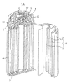
図1は、本実施の形態に係る円筒形アルカリ蓄電池の斜視図である。
このアルカリ蓄電池は、ニッケル活物質を含むニッケル正極1(以降、単に正極という。)と水素吸蔵合金を含む負極2とがセパレータ3を介して積層され渦巻状に巻かれてなる円柱状の電極群4と、これらを収容する円筒状の外装缶6等から構成されたニッケル−水素アルカリ蓄電池であって、電極群4にはアルカリ電解液が含浸されている。
【0014】
正極1は、水酸化ニッケルを主成分とする粉末からなる正極活物質が、結着剤によって結着された状態でニッケル3次元多孔体に充填され、所定の厚さに圧延成形されたものである。
負極2は、渦巻板状のパンチングメタルの両面に、水素吸蔵合金が結着剤によって結着されて、所定の厚さに圧延成形されたものである。
【0015】
外装缶6上端の円形の開口部には、ガスケット11を介在させて、中央部が開口された封口板12が配設され、この封口板12に正極端子13が装着されている。この封口板12には弁板8、おさえ板9が載置され、おさえ板9はコイルスプリング10で押圧する構造となっている。そして、弁板8、おさえ板9、コイルスプリング10は、電池内圧が上昇したときに矢印A方向に押圧されて、弁板部に間隙が生じ、内部のガスが大気中に放出されるようになっている。
【0016】
負極2は、負極集電体5により外装缶6の底辺部に電気的に接続され、外装缶6が負極端子を兼ねており、正極端子13は、正極集電体7及び封口板12を介して正極1と電気的に接続されている。
電池の理論容量は正極1によって規定されており、負極2の容量はそれより大きく設定されている。
【0017】
(正極の厚さ,活物質充填密度及びニッケル3次元多孔体の多孔度についての説明)
正極1は、圧延後の厚さが0.80mm〜1.00mmの範囲に設定されている。また、正極活物質の充填密度は、2.5〜2.9g/ccの範囲に設定されている。これによって、以下に説明するように、電池の高率充放電特性や高温充電特性を損なうことなしに、電池の高容量化を達成することができる。
【0018】
従来の円筒形ニッケル−水素アルカリ蓄電池において、正極の圧延後の厚さは通常0.6mm程度に設定されていたが、このように正極1の厚さをより大きく設定することによって、電極群4の体積は変えずに正極1の占有体積をより大きくすることが可能となる。
これは、電極群4の体積を一定としたとき、正極1の厚さを大きく設定するほど、正極1の長さは短くなり、それに伴って、セパレータ3の長さも短くなり、電極群4中のセパレータ3の占有体積が減少するため、その分だけ正極1及び負極2の体積を増やすことが可能となるからである。なお、正極1の長さが短く設定されると、負極2の長さもそれに伴って短く設定されることになる。
【0019】
従来は、正極の活物質充填密度は3.0g/cc−void程度であって、この場合は、正極1の厚さを大きく設定すると電池の高率充放電特性および高温充電特性は低下する。
高率充放電特性が低下するのは、一般的に電極の厚みを大きくすると電極中のイオンの移動距離は大きくなり、イオンの移動性が低下する傾向が現れるが、電極の空隙が少ない場合、電極中に含まれる電解液量が少ないので、その傾向がより顕著に現れるためと考えられる。
【0020】
一方、高温充電特性が低下するのは、正極の厚みが大きくなると容量比を確保するために対向する負極の厚みを大きくする必要があるため、従来の充填密度では過充電時の負極での酸素ガス吸収に伴う発熱反応量が増大し、正極温度が上昇するためと考えられる。
しかし、正極1の活物質の充填密度を2.9g/cc以下の低い範囲に設定することによって、厚みを大きくしても電池の高率充放電特性および高温充電特性の低下を抑制することができる。
【0021】
高率充放電特性の低下が抑制されるのは、活物質充填密度が緩和されるので、厚みが大きくなっても電極中の空隙に電解液が十分確保されることとなり、イオンの移動が妨げられないためと考えられる。
また、高温充電特性の低下が抑制されるのは、電解液が電極中に十分に確保されるため、正極でのトータル比熱が上昇することにより正極の温度上昇が抑制されるためと考えられる。
【0022】
正極の厚みを0.80mmとした場合、高率充放電特性や高温充電特性は、充填密度が低いほど効果はあるが、従来(正極厚さ0.6mm)と比べ高い電池容量を得るためには、2.5g/cc−void以上に設定することが必要と思われる。
また、正極1の基体であるニッケル3次元多孔体としては、厚み方向の平均孔数が3.6〜5.6個/mmのものを用いている。
【0023】
過放電の過程では活物質間のコバルト化合物が水酸化ニッケル粒子内部に拡散して活物質間の導電性が低下し、正極の厚みが大きくなると活物質間の導電性低下の影響が顕著に現れて過放電特性が低下する傾向があるが、このように基体の厚み方向の平均孔数が3.6個/mm以上のものを用いれば、基体と活物質との接触が良好となり、基体−活物質間の抵抗による電圧降下が小さくなり、過放電特性および高率充放電特性を向上させる効果がある。
【0024】
一方、平均孔数が5.6個/mmを越えると、特性向上の効果はあるが、活物質充填作業において抵抗が増して充填しにくくなり生産性が低下する。
(正極活物質についての説明)
正極活物質としては、ニッケル電極の活物質に通常用いられている水酸化ニッケルを主成分とする粉末を用いることができるが、水酸化ニッケルの表面にナトリウムを含有する高次のコバルト化合物からなる被覆層が形成された複合体粒子に対して、2価以下のコバルト化合物,金属イットリウムまたはイットリウム化合物が添加された混合粉末を用いることが好ましい。
【0025】
ここで被覆層を形成する高次のコバルト化合物は、導電性が良好であるため活物質の利用率を向上させ、これにナトリウムが含有されていることによって、更に導電性の向上効果が高められるものと考えられる。
被覆層におけるナトリウムの含有量としては、複合体粒子に対して0.1〜10重量%が適当である。
【0026】
また、このように2価以下のコバルト化合物を添加することによって、それが初回充電時に上記高導電性水酸化ニッケル(ナトリウム含有コバルト化合物被覆水酸化ニッケル)の粒子間、あるいは当該粒子−ニッケル3次元多孔体間に導電性ネットワークを形成し、さらに、導電性が向上される。
また、金属イットリウムやイットリウム化合物を添加することによって、過放電時、被覆層に含まれるコバルトが水酸化ニッケル粒子内部へ拡散するのを抑制することができるので、電池の過放電特性および高率充放電特性は損なわれにくい。
【0027】
また、金属イットリウムやイットリウム化合物を添加することによって正極の酸素発生過電圧が増大し、高温での充電効率も向上する。
なお、水酸化ニッケルを主成分とする粉末中に、亜鉛、カドミウム、カルシウム、マグネシウム、ビスマス、アルミニウムおよびイットリウムの何れか一元素あるいは複数元素の混合物を固溶させてもよい。
【0028】
上記のような正極活物質は、次のようにして作成することができる。
硫酸ニッケル水溶液を攪拌しながら、アルカリでpHを調整して水酸化ニッケル粒子を作製する。ここで、硫酸ニッケル溶液中に亜鉛,カドミウム,コバルトの塩等を混合しておけば、これらを固溶させた水酸化ニッケル粒子を作製することができる。
【0029】
水酸化ニッケルを主成分とする粒子を分散させた水溶液を攪拌しながら、硫酸コバルト水溶液と水酸化ナトリウム水溶液とを滴下してpHを弱アルカリ性に維持することによって、水酸化ニッケルの結晶を核とし、その表面に水酸化コバルトが析出した粒状物が生成する。
この粒状物を攪拌しながら、これに水酸化ナトリウム水溶液を加えて含浸させると共に所定温度(50〜200℃)で加熱するというアルカリ熱処理を行う。
【0030】
このアルカリ熱処理で、表面の水酸化コバルトの一部が高次化されると共にナトリウムが含有され、水酸化ニッケルの結晶の状態も電池の過放電特性にとって有利に変化すると考えられる。
そして、このようにアルカリ熱処理した粒状物に対して、2価以下のコバルト化合物(例えば、水酸化コバルト粉末),イットリウム,イットリウム化合物(例えば、三酸化二イットリウム,炭酸イットリウム,フッ化イットリウム),或はこれらの混合物を添加し混合することによって、正極活物質が作製される。
【0031】
コバルト化合物,イットリウム,イットリウム化合物等の添加量は、活物質全体に対して0.05〜5重量%が適当である。
なお、高次のコバルト化合物の被覆層を形成する方法としては、金属コバルトを水酸化ニッケル粒子に添加して付着させ、その後同様にアルカリ熱処理する方法もある。
【0032】
さらに、上記の正極活物質において、被覆層のコバルト化合物が高次化されていない場合でも、ナトリウムが含有されていれば、ある程度の高率充放電特性や過放電特性を向上する効果があるものと考えられる。
〔実施の形態2〕
図2は、本実施の形態に係る角形アルカリ蓄電池の斜視図である。
【0033】
この角形アルカリ蓄電池は、ニッケル活物質を含む複数枚の正極21と水素吸蔵合金を含有する複数枚の負極22とがセパレータ23を介して積層されてなる直方体状の電極群24と、これらを収容する外装缶25等からなるニッケル−水素アルカリ蓄電池であって、電極群24にはアルカリ電解液が含浸され、電極群24と外装缶25との間は絶縁シート26で仕切られている。
【0034】
そして、外装缶25の上面25aには、正極21と接続された正極端子27,負極22と接続された負極端子28,安全弁29が設けられている。
正極21及び負極22は、長方形の平板状であるが、ニッケル3次元多孔体及び正極活物質等の基本的な構成は、実施の形態1の正極1及び負極2と同様である。
【0035】
この正極21においても、圧延後の厚さは0.80mm〜1.00mmの範囲に設定されており、正極活物質の充填密度は、2.5〜2.9g/ccの範囲に設定されている。
このように正極21を従来の0.6mm程度より厚くすることによって、セパレータ23の枚数を少なくし、その分正極21の容量を大きく設定できる。
【0036】
これによって、実施の形態1の場合と同様の理由で、電池の高率充放電特性や高温充電特性、また、過放電特性の低下を抑制することができる。。
【0037】
【実施例】
〔実施例1〕
(ニッケル正極の作製)
硫酸コバルト13.1gの水溶液1リットルに、亜鉛:2.5重量%,コバルト:1重量%が固溶した水酸化ニッケル粉末を入れ、これを攪拌しながら1Mの水酸化ナトリウム水溶液を徐々に滴下し、反応中pHを11に保持することによって、水酸化ニッケル粒子を核とし、その表面に水酸化コバルトの被覆層が形成された粒状物を作製した。
【0038】
このようにして作製された粒状物を分取して洗浄,乾燥する(粉末A)。
そして、粉末Aをビーカ中で攪拌しながら、これに25重量%の水酸化ナトリウム水溶液を重量比で10倍量加えて含浸させ、8時間、攪拌しながら空気中,85℃で加熱処理することによるアルカリ熱処理した。これを分取,水洗および脱水して65℃で乾燥することによって、水酸化コバルト被覆層に1重量%のナトリウムを含有する複合体粒子(粉末Bとする)を作製した。
【0039】
このアルカリ熱処理工程で、水酸化コバルトの一部が高次化されると共に、ナトリウムが含有される。
このようにして得られた複合体粒子である粉末Bと、水酸化コバルト,酸化亜鉛,三酸化二イットリウム(Y2O3)を表1に示す所定の重量比(重量%)で混合することによって活物質を作製した。
【0040】
【表1】

活物質粉末100重量部に対して0.2wt%のヒドロキシプロピルセルロース水溶液を50重量部とを混合し活物質スラリー液とした。
【0041】
この活物質スラリー液を、多孔度95%,厚み2.1mmで、厚み方向に4.0個/mmの平均孔数を有するニッケル3次元多孔体である発泡ニッケル基体に、充填し、乾燥後、所定の厚み(0.80,0.90,1.00mm)に圧延して、50mm×50mmの寸法に切断し、正極1〜15を作製した。
ここで、圧延後の活物質充填密度が所定の値(2.5,2.6,2.7,2.8,2.9g/cc−void)となるように設定した。
【0042】
下記表2には、作製した正極1〜15について、厚みと活物質充填密度(g/cc−void)が示されている。
【0043】
【表2】
電子顕微鏡によって50箇所で所定径の円形状の孔に換算して計数し、その平均値を算出した。
[充填密度の測定方法]
まず正極の重量と体積を測定しておく。
【0044】
次に、正極を溶媒中、超音波洗浄器で洗浄することによって正極活物質を脱落させ、乾燥したのち残された発泡ニッケルの重量を測定する。その重量値をニッケル比重で除して発泡ニッケルの体積を求め、これと先に測定した正極の体積との差を正極の孔の体積とする。
一方、溶媒で脱落されたものを乾燥しその重量も測定し、その値を正極に保持されていた正極活物質の重量とする。
【0045】
そして、孔の体積に対する正極活物質の重量の値を、正極における正極活物質の充填密度とする。
[ナトリウム含有量の測定]
水酸化コバルト被覆層中のナトリウム含量の測定は原子吸光分析法により行い、粉末Bでのナトリウム含量を算出し、その数値からアルカリ熱処理を施す前段階の粉末Aのナトリウム含量を減算した。
【0046】
(負極の作製)
市販の金属元素をMmNi3.4Co0.8Al0.2Mn0.6となるように秤量し、高周波溶解炉にて溶解したのち、この溶湯を鋳型に流し込み、水素吸蔵合金インゴットを作製した。次にこのインゴットをあらかじめ阻粉砕したのち、不活性ガス雰囲気中で平均粒径が150μm程度になるまで機械的に粉砕を行った。
【0047】
この合金粉末に結着剤としてポリエチレンオキサイド等、および、適量の水を加えて混合してスラリーを作製した。このスラリーをパンチングメタルからなる集電体の両面に塗着した。塗着量は、圧延のちの活物質密度が5g/ccとなるように調整した。その後、乾燥、圧延を行ったのち、50×50mmの寸法に切断して負極とする。
【0048】
(電池の作製)
そして、前記各正極と負極を用いて角形の密閉式ニッケル−水素蓄電池を次のようにして作製した。
まず、所定寸法に切断した正極を厚み0.2mmのポリプロピレン製不織布からなるセパレータで包み、この正極を理論容量比が正極の1.8倍以上となるような十分大きな容量を持つ負極2枚で挟んで電極群とする。この電極群をこれよりも若干大きめのサイズの外装缶に挿入し、これにLiOHおよびNaOHを含有した7〜8.5NのKOH水溶液を注入したのち、正極リード線が溶接された封口体とこの外装缶とをレーザーにて溶接した。
【0049】
なお、電極群の厚みが一定となるように負極厚みは正極厚みに応じて調整し、電極群の電池内の占有体積を一様にしたものを作製した。
(実験1)
正極1〜15を用いて作製された各電池および比較例の電池について、高率放電特性を評価し、正極の厚み及び活物質充填密度と高率放電特性との関係を調べた。
【0050】
比較例の電池は、表2に示すように厚みを0.70mmとし、また、活物質充填密度を3.0,3.1,3.2g/cc−voidとした以外は正極8と同様にして作製された正極38〜54を用いて作製した。
高率放電特性の評価は以下のようにして行った。
[電池活性化]
まず、正極活物質1g当たり30mA(以下、正極活物質1g当たりの電流値mAを単にmA/gと表記する。)の電流値で16時間充電し、次いで60mA/gの電流値で電池電圧が1.0Vに達するまで放電するというサイクルを6サイクル繰り返して電池を活性化した。この6サイクル目の放電容量(mAh,表2の電池容量)を測定し、この容量を正極活物質1g当たりの容量(以下、基準容量と表記する。mAh/g)を算出した。
【0051】
[高率放電特性の評価]
次に、基準容量測定後の電池を30mA/gの電流値で16時間充電し、1時間の休止の後、300mA/gの電流値で電池電圧が1.0Vに達するまで放電し、このときの正極活物質1g当たり放電容量の各電池の基準容量に対する割合(放電容量/基準容量;%)を高率放電特性とした。
【0052】
実験の結果を表2に示す。この表では高率放電特性の値は、正極8の電池の場合を100とした相対値で示している。なお、以下の表4〜表8においても高率放電特性,過放電特性および基準容量の値は同様に、正極8を用いた電池の場合を100とした相対値で表記する。
これに示すように、正極厚みが0.7mmでは充填密度が3.0〜3.2g/cc−voidと大きいものでも、高率放電特性の低下は殆どみられない。一方、充填密度が3.0〜3.2g/cc−voidの場合、正極厚みが0.80mm以上では厚みが大きくなるほど特性低下の割合が大きいが、充填密度を2.9g/cc−void以下に規制することにより、特性低下は抑制されることがわかる。
【0053】
本実験ではニッケル3次元多孔体の幅方向の孔数が4.0個/mmのものを用いて行ったが、孔数の少ないものを用いた場合でも、同様の傾向があることを確認した。
(実験2)
前記正極8を用いた電池において、活物質における水酸化コバルトの添加形態を変えた場合の高率放電特性および過放電特性について検討した。
【0054】
比較例の電池には、亜鉛:2.5重量%、コバルト:1重量%が固溶した水酸化ニッケル粉末100重量部と水酸化コバルト粉末7.85重量部とを混合した粉末C(粉末Bの水酸化コバルト量と同量の水酸化コバルトを含有することになる。)と酸化亜鉛、水酸化コバルト、三酸化二イットリウムとを正極8と同様の比率で混合して活物質とし、正極8と同様にして作製した正極56を用いて作製した。
【0055】
また、粉末Cの代わりに粉末Aを用いて正極56と同様にして作製した正極55も用いた。
過放電特性の評価は以下のようにして行った。
[過放電特性の評価]
前記基準容量測定後の電池を300mA/gの電流値で、電池電圧がピークに達し、ピーク電圧値からの電圧降下量(−ΔV値)が10mVに達するまで充電を行う。そして、1時間休止ののち300mA/gの電流値で電池電圧が1.0Vに達するまで放電を行う。ここでこのときの放電容量を初回値として記録しておき、引き続いて15mA/gの電流値で16時間の強制放電を行う。このような操作を5サイクル繰り返し、5サイクル目の放電容量を測定する。このときの放電容量の初回値に対する割合(5サイクル目/初回値;%)を電池の過放電特性とした。
【0056】
表3に実験の結果を示す。
【0057】
【表3】
【0058】
また、正極8を用いた電池では、正極56を用いた電池に比べて過放電特性が優れるのは、水酸化ニッケル粒子表面のコバルト化合物が過放電状態にあっても安定であり、水酸化ニッケル粒子内へのコバルトの拡散が防止されるためと考えられる。
〔実施例2〕
本実施例の電池は、ニッケル3次元多孔体の厚み方向の平均孔数を3.6〜5.6個/mmと変化させた以外は前記実験1で最も優れていた正極8と同様にして作製された正極16〜21を用い、実施例1の電池と同様にして作製されたものである(表4参照)。
【0059】
なお、電池の作製方法については、以降の各実施例でも実施例1と同様である。
【0060】
【表4】
前記正極8,正極16〜21を用いた電池および比較例の電池について高率充放電特性および過放電特性を評価し、ニッケル3次元多孔体の厚み方向の孔数との関係を調べた。
【0061】
比較例の電池は、表4に示すようにニッケル3次元多孔体の厚み方向の孔数を3.0,3.2,3.3,3.45,3.5と変化させて正極8と同様にして作製された正極57〜61を用いて作製した。表4に実験の結果を示す。
これに示すようにニッケル3次元多孔体の厚み方向の平均孔数が、3.6個/mm未満では各特性が低下するが、3.6個/mm以上に設定すれば、高率放電特性及び過放電特性が良好であることがわかる。
【0062】
〔実施例3〕
本実施例の電池は、活物質における三酸化二イットリウムの添加量を0.05〜5重量%の範囲で変化させた以外は、前記正極8と同様にして作製された正極22〜25を用いたものである(表5参照)。
【0063】
【表5】
本実験では、正極8,正極22〜25を用いた電池および比較例の電池の高率放電特性および過放電特性を評価し、それら特性と三酸化二イットリウムの添加量との関係について調べた。
【0064】
比較例の電池は、表5に示すように三酸化二イットリウムを0,0.01,7.5,10重量部と変化させて正極8と同様にして作製された正極62〜65を用いて作製した。実験結果を表5に示した。
これに示すように両特性を維持する上で三酸化二イットリウムの添加量は、0.05重量%〜5重量%が最適であることがわかる。
【0065】
添加量が0.05重量%未満の場合に過放電特性が低下するのは、過放電時に被覆層に含まれるコバルトの水酸化ニッケル粒子内部への拡散を十分に抑制することができないためと考えられる。
一方、添加量が5重量%を越えると高率放電特性が低下するのは、一つには活物質間の導電性が低下するため、並びに、主活物質である水酸化ニッケルの相対量が減少し、電極容量が低下するためであると考えられる。
【0066】
なお、本実験ではイットリウム化合物として三酸化二イットリウムを用いたが、金属イットリウム,炭酸イットリウム,フッ化イットリウムを用いた場合でも同様の効果があることを確認した。
〔実施例4〕
本実施例の電池は、粉末Bと混合する水酸化コバルトの添加量を活物質に対して0.05〜5重量%の範囲で変化させてある以外は正極8と同様に作製された正極26〜29を用いたものである(表6参照)。
【0067】
【表6】
本実験では、正極8,正極26〜29を用いた電池および比較例の電池について高率放電特性および過放電特性を評価し、活物質中の水酸化コバルトの添加量との関係について調べた。
【0068】
比較例の電池は、表6に示すように水酸化コバルトの添加量を0,0.01,7.5,10重量部と変化させて正極8と同様に作製された正極66〜69を用いて作製した。実験結果を表6に示した。
これに示すように両特性を維持する上で、水酸化コバルトの添加量は、活物質全体に対して0.05重量%〜5重量%が好ましことがわかる。
【0069】
水酸化コバルトの添加量が0.05重量%未満になると高率放電特性が低下するのは、2価以下のコバルトによる導電性ネットワークが十分形成されず、さらに、接触抵抗を低減するに到らないからと考えられる。また、前述の過放電特性向上に効果のある酸化イットリウムの添加による導電性の低下を抑制できないためと考えられる。
【0070】
一方、添加量が5重量%を越えると過放電特性が低下する。これは、2価以下のコバルト化合物が多すぎると、初充電時に十分高次化が進行せず、コバルトの平均価数が2近くになり、この状態で過放電状態におかれると活物質粒子間のコバルトが水酸化ニッケル粒子内部に拡散し、結果として導電性ネットワークが破壊されるためと考えられる。また、前述の過放電特性に効果のあるナトリウム含有コバルト化合物が相対的に少なくなるためとも考えられる。
【0071】
なお、本実験では2価以下のコバルト化合物として水酸化コバルトを用いたが、金属コバルト、酸化コバルトを用いた場合にも同様の結果を得た。
〔実施例5〕
本実施例の電池では、アルカリ熱処理の水酸化ナトリウム水溶液の濃度を10,15,35,40重量%と変化させることにより、含有ナトリウム量が0.1,0.5,5,10重量%の粉末Bを作製してある以外は正極8と同様に作製された正極30〜33を用いたものである(表7参照)。
【0072】
【表7】
本実験では、正極8,正極30〜33を用いた電池および比較例の電池の基準容量を測定し、ナトリウム含有量と基準容量との関係を調べた。
比較例の電池は、表7に示すように水酸化ナトリウム水溶液の濃度が5重量%,45重量%,50重量%と変化させて得た粉末Bから正極8のようにして作製した正極70〜72を用いて作製した。実験結果を表7に示す。
【0073】
これに示すように、活物質利用率の高い非焼結式ニッケル極を得る上で、ナトリウム含有コバルト化合物のナトリウム含有率は粉末Bに対して0.1〜10重量%が好ましいことがわかる。
〔実施例6〕
本実施例の電池は、活物質作製時のアルカリ熱処理における処理温度を50,100,150,200℃と変化させて粉末Bを作製してある以外は、正極8と同様に作製された正極34〜37を用いたものである(表8参照)。
【0074】
【表8】
本実験では、正極8,正極34〜37を用いた電池および比較例の電池の基準容量(mAh/g)を測定し、アルカリ熱処理の処理温度と基準容量との関係について調べた。
【0075】
比較例の電池は、処理温度を45℃,220℃および250℃と変化させて得た粉末Bから正極8のようにして作製した正極73〜75を用いて作製した。実験結果を表8に示した。
これに示すように、活物質利用率の高い非焼結式ニッケル極を得る上で、50〜200℃の温度で加熱処理することが好ましいことがわかる。
【0076】
これは50℃未満になるとコバルト高次化のための酸化が十分なされず、一方、200℃を越えると酸化が進行し過ぎてしまって、水酸化ニッケルまでも酸化されるためと考えられる。
【0077】
【発明の効果】
以上述べてきたように、本発明のアルカリ蓄電池用比非焼結式ニッケル極によれば、その厚みが0.80mm以上の場合にも、その活物質充填密度を2.9g/cc−void以下に設定することにより、電池の高容量化を実現すると共に、高率充放電特性および高温充電特性の低下を抑制することができる。この場合、2.5g/cc−void以上の範囲において、より望ましい。
【0078】
また、ニッケル3次元多孔体の厚み方向の孔数は平均値で3.6個/mm以上にすることで、厚みが大きくなっても活物質間の接触が十分になり、ニッケル多孔体と活物質間の電圧効果が軽減されるので、過放電効率の低下を抑制することができる。
この場合、孔数は平均値で5.6個/mm以下の範囲でれば、活物質をニッケル3次元多孔体に充填しやすいのでより望ましい。
【図面の簡単な説明】
【図1】実施の形態1の係る円筒形アルカリ蓄電池の斜視図である。
【図2】実施の形態2に係る角形アルカリ蓄電池の斜視図である。
【符号の説明】
1 ニッケル正極
2 負極
3 セパレータ
4 電極群
5 負極集電体
6 外装缶
7 正極集電体
8 弁板
9 おさえ板
10 コイルスプリング
11 ガスケット
12 封口板
13 正極端子
21 ニッケル正極
22 負極
23 セパレータ
24 電極群
25 外装缶
26 絶縁シート
27 正極端子
28 負極端子
29 安全弁[0001]
TECHNICAL FIELD OF THE INVENTION
The present invention relates to a non-sintered nickel electrode for an alkaline storage battery filled with an active material mainly composed of nickel hydroxide.
[0002]
[Prior art]
An alkaline storage battery using a nickel electrode as a positive electrode represented by a nickel-cadmium secondary battery or a nickel-hydrogen secondary battery has a positive electrode containing nickel hydroxide as an active material and a negative electrode containing cadmium or a hydrogen storage alloy as an active material. Are arranged via a separator to form an electrode group, which is housed in an outer can in a state of being impregnated with an alkaline electrolyte.
[0003]
In realizing high capacity in such an alkaline storage battery, it is an issue how to increase the capacity of the positive electrode, that is, the nickel electrode, which is the dominant electrode of the battery. A non-sintered nickel electrode in which a nickel three-dimensional porous body is filled with a nickel active material is suitable for increasing the capacity in that the packing density of the active material can be increased, but as one method for further increasing the capacity. In addition, the volume occupied by members not directly involved in the electrochemical reaction, such as a separator, is reduced, and the volume occupied by the nickel electrode is increased.
[0004]
This can be achieved by increasing the thickness of the nickel electrode. That is, for a cylindrical battery, the thickness of the nickel electrode may be increased to reduce the number of turns, and the length of the electrode plate may be reduced. For a rectangular battery, the thickness of the nickel electrode may be similarly increased. What is necessary is just to reduce the number of electrode plates.
[0005]
[Problems to be solved by the invention]
However, when attempting to increase the capacity of the battery simply by increasing the thickness of the nickel electrode as described above, there is a problem that the high-rate charge / discharge characteristics, the high-temperature charge characteristics, or the over-discharge characteristics are reduced, and the battery is put to practical use. Need to solve this.
On the other hand, it is conceivable to increase the volume occupied by the electrodes by reducing the thickness of the separator, but it is not desirable to make the separator thin, since short-circuiting is likely to occur.
[0006]
The present invention has been made in view of the above-mentioned problems, and has been made in consideration of the above-mentioned problems. It is intended to provide a combined nickel electrode.
[0007]
[Means for Solving the Problems]
In order to achieve the above object, the present invention provides a non-sintered nickel electrode for an alkaline storage battery, in which an active material powder mainly composed of nickel hydroxide is filled into a three-dimensional porous nickel material and rolled, Was set to 0.80 mm or more, and the active material packing density was set to 2.9 g / cc-void or less.
[0008]
The active material packing density (g / cc-void) means the weight of the filled active material with respect to the volume of the pores of the nickel three-dimensional porous body.
By setting the thickness and the active material filling density in this way, it is possible to realize a higher capacity of the battery and to suppress a decrease in high-rate charge / discharge characteristics and high-temperature charge characteristics. In this case, it is more desirable that the active material packing density be in the range of 2.5 g / cc-void or more.
[0009]
Furthermore, when the nickel three-dimensional porous body having an average number of holes in the thickness direction of 3.6 / mm or more is used, even if the thickness of the nickel electrode is increased, the high-rate charge / discharge characteristics and the overdischarge characteristics are impaired. It is hard to be. In this case, it is more preferable that the average number of holes be in a range of 5.6 / mm or less.
Furthermore, as an active material powder, a bivalent or lower valent cobalt compound and a metal yttrium and / or a yttrium compound were added to a composite particle in which a coating layer made of a sodium-containing cobalt compound was formed on the surface of nickel hydroxide particles. When the mixed powder is used, the high-rate charge / discharge characteristics and the overdischarge characteristics of the battery are hardly impaired even if the thickness of the nickel electrode is increased.
[0010]
The addition amount of the divalent or lower valent cobalt compound is desirably 0.05 to 5% by weight based on 100 of the active material powder.
It is desirable that the metal yttrium and / or the yttrium compound be contained in an amount of 0.05 to 5% by weight based on the active material powder.
Further, as the composite particles, those formed by adding an aqueous solution of sodium hydroxide to a material obtained by adding metal cobalt or a cobalt compound to the surface of nickel hydroxide particles and performing a heat treatment in the presence of oxygen are used. If this is the case, the conductivity of the active material can be further improved.
[0011]
Here, it is desirable that the sodium content in the coating layer is 0.1 to 10% by weight based on the composite particles.
Examples of the sodium-containing cobalt compound include sodium-containing cobalt hydroxide, sodium-containing cobalt oxyhydroxide, and a mixture thereof.
[0012]
Examples of the yttrium compound include yttrium trioxide, yttrium carbonate, and yttrium fluoride.
Further, as the nickel hydroxide particles, particles in which at least one element selected from the group consisting of cobalt, zinc, cadmium, calcium, magnesium, bismuth, aluminum, and yttrium can be used.
[0013]
BEST MODE FOR CARRYING OUT THE INVENTION
[Embodiment 1]
(Explanation of the overall configuration of the alkaline storage battery)
FIG. 1 is a perspective view of a cylindrical alkaline storage battery according to the present embodiment.
This alkaline storage battery has a columnar electrode group in which a nickel
[0014]
The
The
[0015]
In the circular opening at the upper end of the
[0016]
The
The theoretical capacity of the battery is defined by the
[0017]
(Explanation of thickness of positive electrode, packing density of active material and porosity of nickel three-dimensional porous body)
The
[0018]
In a conventional cylindrical nickel-hydrogen alkaline storage battery, the thickness of the positive electrode after rolling is usually set to about 0.6 mm. By setting the thickness of the
That is, when the volume of the
[0019]
Conventionally, the active material filling density of the positive electrode is about 3.0 g / cc-void. In this case, when the thickness of the
The high-rate charge / discharge characteristics decrease because, generally, when the thickness of the electrode is increased, the movement distance of the ions in the electrode increases, and the mobility of the ions tends to decrease. This is considered to be because the amount of the electrolyte contained in the electrode was small, and the tendency was more remarkable.
[0020]
On the other hand, the high-temperature charging characteristics decrease because the thickness of the opposite anode must be increased in order to secure a capacity ratio when the thickness of the cathode is increased. It is considered that the amount of exothermic reaction accompanying gas absorption increases and the temperature of the positive electrode increases.
However, by setting the filling density of the active material of the
[0021]
The reduction in the high-rate charge / discharge characteristics is suppressed because the active material filling density is relaxed, so that even if the thickness is increased, the electrolyte is sufficiently secured in the voids in the electrode, and the movement of ions is hindered. Probably because it cannot be done.
Further, it is considered that the decrease in the high-temperature charging characteristics is suppressed because the electrolyte is sufficiently ensured in the electrode, and the temperature rise of the positive electrode is suppressed by increasing the total specific heat at the positive electrode.
[0022]
When the thickness of the positive electrode is set to 0.80 mm, high-rate charge / discharge characteristics and high-temperature charge characteristics are more effective as the packing density is lower, but in order to obtain a higher battery capacity as compared with the conventional (positive electrode thickness: 0.6 mm). Seems to need to be set to 2.5 g / cc-void or more.
The nickel three-dimensional porous body serving as the base of the
[0023]
In the process of overdischarge, the cobalt compound between the active materials diffuses into the nickel hydroxide particles and the conductivity between the active materials decreases, and as the thickness of the positive electrode increases, the effect of the decrease in the conductivity between the active materials appears remarkably. However, the use of a substrate having an average number of pores in the thickness direction of 3.6 or more as described above makes the contact between the substrate and the active material good, and The voltage drop due to the resistance between the active materials is reduced, which has the effect of improving overdischarge characteristics and high-rate charge / discharge characteristics.
[0024]
On the other hand, when the average number of pores exceeds 5.6 / mm, the effect of improving the properties is obtained, but the resistance increases in the active material filling operation, so that the filling becomes difficult and the productivity is reduced.
(Description of positive electrode active material)
As the positive electrode active material, a powder containing nickel hydroxide as a main component, which is generally used as an active material for a nickel electrode, can be used. The surface of the nickel hydroxide is composed of a higher-order cobalt compound containing sodium. It is preferable to use a mixed powder in which a cobalt compound having a valence of 2 or less, metal yttrium, or a yttrium compound is added to the composite particles on which the coating layer is formed.
[0025]
Here, the higher-order cobalt compound that forms the coating layer improves the utilization rate of the active material because of its good conductivity, and the fact that sodium is contained therein further enhances the effect of improving the conductivity. It is considered.
The content of sodium in the coating layer is suitably from 0.1 to 10% by weight based on the composite particles.
[0026]
In addition, by adding a cobalt compound having a valence of 2 or less as described above, it is possible to add the cobalt compound between the particles of the highly conductive nickel hydroxide (nickel hydroxide coated with a sodium-containing cobalt compound) at the time of the first charge or between the particle and the nickel. A conductive network is formed between the porous bodies, and the conductivity is further improved.
In addition, by adding metallic yttrium or a yttrium compound, it is possible to suppress the cobalt contained in the coating layer from being diffused into the nickel hydroxide particles during overdischarge, so that the overdischarge characteristics and high efficiency of the battery are improved. Discharge characteristics are not easily impaired.
[0027]
In addition, the addition of metal yttrium or a yttrium compound increases the oxygen overvoltage of the positive electrode and improves the charging efficiency at high temperatures.
Note that any one of zinc, cadmium, calcium, magnesium, bismuth, aluminum, and yttrium or a mixture of a plurality of elements may be dissolved in a powder containing nickel hydroxide as a main component.
[0028]
The positive electrode active material as described above can be prepared as follows.
While stirring the aqueous nickel sulfate solution, the pH is adjusted with an alkali to produce nickel hydroxide particles. Here, if zinc, cadmium, cobalt salts and the like are mixed in the nickel sulfate solution, nickel hydroxide particles in which these are dissolved can be produced.
[0029]
While stirring the aqueous solution in which the particles mainly composed of nickel hydroxide are dispersed, an aqueous solution of cobalt sulfate and an aqueous solution of sodium hydroxide are added dropwise to maintain the pH at a slightly alkaline level, so that the nickel hydroxide crystals are used as nuclei. As a result, particulate matter on which cobalt hydroxide is precipitated is generated.
While stirring the granules, an alkali heat treatment is performed in which an aqueous sodium hydroxide solution is added thereto to impregnate the granules and heat them at a predetermined temperature (50 to 200 ° C.).
[0030]
It is thought that the alkali heat treatment partially increases the cobalt hydroxide on the surface and contains sodium, and the crystal state of nickel hydroxide also advantageously changes the overdischarge characteristics of the battery.
Then, a cobalt compound having a valence of 2 or less (for example, cobalt hydroxide powder), yttrium, an yttrium compound (for example, yttrium trioxide, yttrium carbonate, yttrium fluoride), or The positive electrode active material is prepared by adding and mixing these mixtures.
[0031]
The addition amount of the cobalt compound, yttrium, yttrium compound, etc. is suitably 0.05 to 5% by weight based on the whole active material.
In addition, as a method of forming a coating layer of a higher-order cobalt compound, there is a method of adding metallic cobalt to nickel hydroxide particles and causing them to adhere thereto, and then performing a similar alkali heat treatment.
[0032]
Furthermore, in the above-mentioned positive electrode active material, even when the cobalt compound of the coating layer is not higher-ordered, if sodium is contained, there is an effect of improving the high-rate charge / discharge characteristics and the overdischarge characteristics to some extent. it is conceivable that.
[Embodiment 2]
FIG. 2 is a perspective view of the prismatic alkaline storage battery according to the present embodiment.
[0033]
This prismatic alkaline storage battery accommodates a rectangular parallelepiped electrode group 24 in which a plurality of positive electrodes 21 containing a nickel active material and a plurality of negative electrodes 22 containing a hydrogen storage alloy are stacked via a separator 23. A nickel-hydrogen alkaline storage battery comprising an
[0034]
On the upper surface 25a of the
Although the positive electrode 21 and the negative electrode 22 are rectangular flat plates, the basic configuration of the nickel three-dimensional porous body, the positive electrode active material, and the like is the same as the
[0035]
Also in this positive electrode 21, the thickness after rolling is set in the range of 0.80 mm to 1.00 mm, and the packing density of the positive electrode active material is set in the range of 2.5 to 2.9 g / cc. I have.
Thus, by making the positive electrode 21 thicker than the conventional thickness of about 0.6 mm, the number of the separators 23 can be reduced, and the capacity of the positive electrode 21 can be set correspondingly large.
[0036]
Thereby, for the same reason as in the first embodiment, it is possible to suppress a decrease in the high-rate charge / discharge characteristics, the high-temperature charge characteristics, and the overdischarge characteristics of the battery. .
[0037]
【Example】
[Example 1]
(Preparation of nickel positive electrode)
To 1 liter of an aqueous solution of 13.1 g of cobalt sulfate, nickel hydroxide powder in which 2.5% by weight of zinc and 1% by weight of cobalt were dissolved was added, and a 1M aqueous solution of sodium hydroxide was gradually added dropwise with stirring. Then, by maintaining the pH at 11 during the reaction, a granular material having nickel hydroxide particles as nuclei and a coating layer of cobalt hydroxide formed on the surface thereof was produced.
[0038]
The granules thus produced are separated, washed and dried (powder A).
Then, while stirring the powder A in a beaker, a 25% by weight aqueous sodium hydroxide solution is added to the powder A in an
[0039]
In this alkali heat treatment step, a part of cobalt hydroxide is converted to higher order and contains sodium.
Powder B, which is a composite particle obtained in this manner, is mixed with cobalt hydroxide, zinc oxide, yttrium trioxide (Y 2 O 3 ) Was mixed at a predetermined weight ratio (% by weight) shown in Table 1 to prepare an active material.
[0040]
[Table 1]
An active material slurry liquid was prepared by mixing 50 parts by weight of a 0.2 wt% aqueous solution of hydroxypropylcellulose with 100 parts by weight of the active material powder.
[0041]
This active material slurry liquid is filled in a foamed nickel substrate, which is a nickel three-dimensional porous body having a porosity of 95%, a thickness of 2.1 mm, and an average number of holes in the thickness direction of 4.0 / mm, and then dried. Then, it was rolled to a predetermined thickness (0.80, 0.90, 1.00 mm) and cut into a size of 50 mm × 50 mm to produce
Here, the active material packing density after rolling was set to a predetermined value (2.5, 2.6, 2.7, 2.8, 2.9 g / cc-void).
[0042]
Table 2 below shows the thickness and active material packing density (g / cc-void) of the produced
[0043]
[Table 2]
Using an electron microscope, 50 holes were converted into circular holes having a predetermined diameter, counted, and the average value was calculated.
[Method of measuring packing density]
First, the weight and volume of the positive electrode are measured.
[0044]
Next, the positive electrode active material is dropped by washing the positive electrode in a solvent with an ultrasonic cleaner, and the weight of the foamed nickel remaining after drying is measured. The weight value is divided by the specific gravity of nickel to determine the volume of the foamed nickel, and the difference between this and the previously measured volume of the positive electrode is defined as the volume of the positive electrode hole.
On the other hand, the material dropped off with a solvent is dried and its weight is measured, and the value is defined as the weight of the positive electrode active material held on the positive electrode.
[0045]
Then, the value of the weight of the positive electrode active material with respect to the volume of the hole is defined as the packing density of the positive electrode active material in the positive electrode.
[Measurement of sodium content]
The sodium content in the cobalt hydroxide coating layer was measured by atomic absorption spectrometry, the sodium content in the powder B was calculated, and the sodium content of the powder A before the alkali heat treatment was subtracted from the calculated value.
[0046]
(Preparation of negative electrode)
Commercially available metal element is MmNi 3.4 Co 0.8 Al 0.2 Mn 0.6 After being weighed and melted in a high-frequency melting furnace, the molten metal was poured into a mold to produce a hydrogen storage alloy ingot. Next, after the ingot was pulverized in advance, it was mechanically pulverized in an inert gas atmosphere until the average particle size became about 150 μm.
[0047]
A slurry was prepared by adding polyethylene oxide or the like as a binder and an appropriate amount of water to the alloy powder and mixing them. This slurry was applied to both surfaces of a current collector made of punching metal. The coating amount was adjusted so that the active material density after rolling was 5 g / cc. Then, after drying and rolling, it is cut into a size of 50 × 50 mm to obtain a negative electrode.
[0048]
(Production of battery)
Then, a rectangular sealed nickel-hydrogen storage battery was produced using the above positive electrode and negative electrode as follows.
First, the positive electrode cut to a predetermined size is wrapped with a separator made of a nonwoven fabric made of polypropylene having a thickness of 0.2 mm, and the positive electrode is wrapped with two negative electrodes having a sufficiently large capacity so that the theoretical capacity ratio becomes 1.8 times or more of the positive electrode. An electrode group is sandwiched therebetween. This electrode group was inserted into a slightly larger outer can, and a 7 to 8.5N KOH aqueous solution containing LiOH and NaOH was injected into the outer can. The outer can was welded with a laser.
[0049]
The thickness of the negative electrode was adjusted in accordance with the thickness of the positive electrode so that the thickness of the electrode group was constant, and the electrode group occupied a uniform volume in the battery.
(Experiment 1)
The high-rate discharge characteristics of each of the batteries prepared using the
[0050]
The battery of the comparative example was the same as the
The evaluation of the high-rate discharge characteristics was performed as follows.
[Battery activation]
First, the battery was charged for 16 hours at a current value of 30 mA per 1 g of the positive electrode active material (hereinafter, the current value mA per 1 g of the positive electrode active material is simply expressed as mA / g), and then the battery voltage was changed at a current value of 60 mA / g. The battery was activated by repeating a cycle of discharging until reaching 1.0 V for 6 cycles. The discharge capacity at the sixth cycle (mAh, battery capacity in Table 2) was measured, and the capacity was calculated as the capacity per 1 g of the positive electrode active material (hereinafter, referred to as reference capacity, mAh / g).
[0051]
[Evaluation of high-rate discharge characteristics]
Next, the battery after the reference capacity measurement was charged at a current value of 30 mA / g for 16 hours, and after a pause of 1 hour, discharged at a current value of 300 mA / g until the battery voltage reached 1.0 V. The ratio of the discharge capacity per 1 g of the positive electrode active material to the reference capacity of each battery (discharge capacity / reference capacity;%) was defined as high-rate discharge characteristics.
[0052]
Table 2 shows the results of the experiment. In this table, the values of the high-rate discharge characteristics are shown as relative values with the case of the battery of the
As shown in the figure, even when the packing density is as large as 3.0 to 3.2 g / cc-void when the thickness of the positive electrode is 0.7 mm, the reduction in the high-rate discharge characteristics is hardly observed. On the other hand, when the packing density is 3.0 to 3.2 g / cc-void, when the thickness of the positive electrode is 0.80 mm or more, the ratio of characteristic deterioration increases as the thickness increases, but the packing density is 2.9 g / cc-void or less. It can be seen that by restricting the characteristic to, the characteristic deterioration is suppressed.
[0053]
In this experiment, a nickel three-dimensional porous body having a number of holes in the width direction of 4.0 / mm was used, but it was confirmed that a similar tendency was obtained even when a small number of holes was used. .
(Experiment 2)
In the battery using the
[0054]
In the battery of the comparative example, powder C (powder B) was prepared by mixing 100 parts by weight of nickel hydroxide powder in which 2.5% by weight of zinc and 1% by weight of cobalt were dissolved and 7.85 parts by weight of cobalt hydroxide powder. Contains the same amount of cobalt hydroxide as the amount of cobalt hydroxide.), Zinc oxide, cobalt hydroxide, and yttrium trioxide in the same ratio as the
[0055]
Further, a positive electrode 55 produced in the same manner as the positive electrode 56 using the powder A instead of the powder C was also used.
The overdischarge characteristics were evaluated as follows.
[Evaluation of overdischarge characteristics]
The battery after the reference capacity measurement is charged at a current value of 300 mA / g until the battery voltage reaches a peak and a voltage drop (-ΔV value) from the peak voltage value reaches 10 mV. After a pause of one hour, discharging is performed at a current value of 300 mA / g until the battery voltage reaches 1.0 V. Here, the discharge capacity at this time is recorded as an initial value, and subsequently, a forced discharge is performed at a current value of 15 mA / g for 16 hours. This operation is repeated for 5 cycles, and the discharge capacity at the 5th cycle is measured. The ratio of the discharge capacity to the initial value at this time (5th cycle / initial value;%) was defined as the overdischarge characteristic of the battery.
[0056]
Table 3 shows the results of the experiment.
[0057]
[Table 3]
[0058]
In addition, the battery using the
[Example 2]
The battery of this example was the same as the
[0059]
The method for manufacturing the battery is the same as in Example 1 in each of the following examples.
[0060]
[Table 4]
The high-rate charge / discharge characteristics and the overdischarge characteristics of the battery using the
[0061]
In the battery of the comparative example, as shown in Table 4, the number of holes in the thickness direction of the nickel three-dimensional porous body was changed to 3.0, 3.2, 3.3, 3.45, and 3.5 to form the
As shown in the figure, when the average number of holes in the thickness direction of the nickel three-dimensional porous body is less than 3.6 / mm, each characteristic decreases. It can be seen that the overdischarge characteristics are good.
[0062]
[Example 3]
The battery of this example uses the positive electrodes 22 to 25 produced in the same manner as the
[0063]
[Table 5]
In this experiment, the high-rate discharge characteristics and the overdischarge characteristics of the battery using the
[0064]
As shown in Table 5, the battery of the comparative example uses positive electrodes 62 to 65 produced in the same manner as the
As shown in the figure, it is understood that the addition amount of yttrium trioxide is optimally 0.05% by weight to 5% by weight in order to maintain both characteristics.
[0065]
It is considered that the reason why the overdischarge characteristic is reduced when the added amount is less than 0.05% by weight is that diffusion of cobalt contained in the coating layer into the nickel hydroxide particles during overdischarge cannot be sufficiently suppressed. Can be
On the other hand, when the addition amount exceeds 5% by weight, the high-rate discharge characteristics decrease because, in part, the conductivity between the active materials decreases, and the relative amount of nickel hydroxide as the main active material decreases. This is considered to be due to the decrease in the electrode capacity.
[0066]
In this experiment, yttrium trioxide was used as the yttrium compound, but it was confirmed that the same effect was obtained when metal yttrium, yttrium carbonate, or yttrium fluoride was used.
[Example 4]
The battery according to the present embodiment was manufactured in the same manner as the
[0067]
[Table 6]
In this experiment, the high-rate discharge characteristics and the overdischarge characteristics of the battery using the
[0068]
As shown in Table 6, the batteries of Comparative Examples used the positive electrodes 66 to 69 produced in the same manner as the
As shown in the figure, in order to maintain both characteristics, it is understood that the amount of cobalt hydroxide added is preferably 0.05% by weight to 5% by weight based on the whole active material.
[0069]
When the added amount of cobalt hydroxide is less than 0.05% by weight, the high-rate discharge characteristics are reduced because a conductive network of divalent or less cobalt is not sufficiently formed, and the contact resistance is further reduced. It is probably because there is no. Further, it is considered that the decrease in conductivity due to the addition of yttrium oxide, which is effective for improving the overdischarge characteristics, cannot be suppressed.
[0070]
On the other hand, if the added amount exceeds 5% by weight, the overdischarge characteristics deteriorate. This is because, when the amount of the cobalt compound having two or less valences is too large, the higher order does not progress sufficiently at the time of the first charge, and the average valence of cobalt becomes close to 2. It is considered that cobalt in between diffuses into the nickel hydroxide particles, and as a result, the conductive network is destroyed. It is also considered that the amount of the sodium-containing cobalt compound that is effective for the above-mentioned overdischarge characteristics is relatively reduced.
[0071]
In this experiment, cobalt hydroxide was used as the divalent or lower valent cobalt compound, but similar results were obtained when metallic cobalt or cobalt oxide was used.
[Example 5]
In the battery of the present embodiment, the concentration of the aqueous sodium hydroxide solution in the alkali heat treatment was changed to 10, 15, 35, and 40% by weight so that the sodium content was 0.1, 0.5, 5, and 10% by weight. Positive electrodes 30 to 33 produced in the same manner as
[0072]
[Table 7]
In this experiment, the reference capacity of the battery using the
As shown in Table 7, the batteries of the comparative examples were prepared as the positive electrode 70 from the powder B obtained by changing the concentration of the aqueous sodium hydroxide solution to 5% by weight, 45% by weight, and 50% by weight. 72. Table 7 shows the experimental results.
[0073]
As shown in this figure, in order to obtain a non-sintered nickel electrode having a high active material utilization rate, the sodium content of the sodium-containing cobalt compound is preferably 0.1 to 10% by weight based on the powder B.
[Example 6]
The battery of this example was manufactured in the same manner as the
[0074]
[Table 8]
In this experiment, the reference capacity (mAh / g) of the battery using the
[0075]
The battery of the comparative example was manufactured using the positive electrodes 73 to 75 manufactured like the
As shown in this figure, in order to obtain a non-sintered nickel electrode having a high active material utilization rate, it is understood that heat treatment at a temperature of 50 to 200 ° C. is preferable.
[0076]
This is presumably because oxidation at a temperature lower than 50 ° C. is not sufficient for increasing the order of cobalt, whereas at a temperature exceeding 200 ° C., oxidation proceeds excessively, and even nickel hydroxide is oxidized.
[0077]
【The invention's effect】
As described above, according to the non-sintered nickel electrode for an alkaline storage battery of the present invention, even when the thickness is 0.80 mm or more, the active material filling density is 2.9 g / cc-void or less. By setting to, the capacity of the battery can be increased, and the deterioration of the high-rate charge / discharge characteristics and the high-temperature charge characteristics can be suppressed. In this case, it is more desirable in the range of 2.5 g / cc-void or more.
[0078]
Further, by setting the number of holes in the thickness direction of the nickel three-dimensional porous body to an average value of 3.6 / mm or more, even if the thickness becomes large, the contact between the active materials becomes sufficient, and the nickel porous body and the active material become active. Since the voltage effect between the substances is reduced, a decrease in the overdischarge efficiency can be suppressed.
In this case, it is more preferable that the number of holes be 5.6 / mm or less on average because the active material can be easily filled in the nickel three-dimensional porous body.
[Brief description of the drawings]
FIG. 1 is a perspective view of a cylindrical alkaline storage battery according to
FIG. 2 is a perspective view of a prismatic alkaline storage battery according to
[Explanation of symbols]
1 Nickel positive electrode
2 Negative electrode
3 separator
4 electrode group
5 Negative electrode current collector
6 outer cans
7 Positive electrode current collector
8 Valve plate
9 Press plate
10 Coil spring
11 Gasket
12 sealing plate
13 Positive terminal
21 Nickel positive electrode
22 negative electrode
23 Separator
24 electrode group
25 Outer can
26 Insulation sheet
27 Positive terminal
28 Negative electrode terminal
29 Safety valve
Claims (11)
圧延後の厚みは0.80mm以上であり、かつ、活物質充填密度は2.9g/cc−void以下であることを特徴とするアルカリ蓄電池用非焼結式ニッケル極。 An active material powder obtained by adding a divalent or less valent cobalt compound and a metal yttrium and / or an yttrium compound to a composite particle in which a coating layer made of a sodium-containing cobalt compound is formed on the surface of nickel hydroxide particles is nickel. A non-sintered nickel electrode for an alkaline storage battery, which is filled and rolled into a three-dimensional porous body,
A non-sintered nickel electrode for an alkaline storage battery, wherein the thickness after rolling is 0.80 mm or more and the active material filling density is 2.9 g / cc-void or less.
Priority Applications (1)
| Application Number | Priority Date | Filing Date | Title |
|---|---|---|---|
| JP00326997A JP3557063B2 (en) | 1997-01-10 | 1997-01-10 | Non-sintered nickel electrode for alkaline storage batteries |
Applications Claiming Priority (1)
| Application Number | Priority Date | Filing Date | Title |
|---|---|---|---|
| JP00326997A JP3557063B2 (en) | 1997-01-10 | 1997-01-10 | Non-sintered nickel electrode for alkaline storage batteries |
Publications (2)
| Publication Number | Publication Date |
|---|---|
| JPH10199520A JPH10199520A (en) | 1998-07-31 |
| JP3557063B2 true JP3557063B2 (en) | 2004-08-25 |
Family
ID=11552744
Family Applications (1)
| Application Number | Title | Priority Date | Filing Date |
|---|---|---|---|
| JP00326997A Expired - Lifetime JP3557063B2 (en) | 1997-01-10 | 1997-01-10 | Non-sintered nickel electrode for alkaline storage batteries |
Country Status (1)
| Country | Link |
|---|---|
| JP (1) | JP3557063B2 (en) |
Families Citing this family (5)
| Publication number | Priority date | Publication date | Assignee | Title |
|---|---|---|---|---|
| JP2002279993A (en) * | 2001-03-22 | 2002-09-27 | Hitachi Maxell Ltd | Alkaline storage battery |
| JP4359100B2 (en) | 2003-08-04 | 2009-11-04 | 三洋電機株式会社 | Cylindrical alkaline storage battery |
| JP4439220B2 (en) | 2003-08-04 | 2010-03-24 | 三洋電機株式会社 | Cylindrical alkaline storage battery and cylindrical nickel metal hydride secondary battery |
| JP2006059807A (en) * | 2004-07-23 | 2006-03-02 | M & G Eco Battery Institute Co Ltd | Nickel electrode and alkali storage battery using the same |
| JP2006100154A (en) * | 2004-09-30 | 2006-04-13 | Sanyo Electric Co Ltd | Alkaline battery and its process of manufacture |
Family Cites Families (5)
| Publication number | Priority date | Publication date | Assignee | Title |
|---|---|---|---|---|
| JPH056762A (en) * | 1991-06-26 | 1993-01-14 | Shin Kobe Electric Mach Co Ltd | Manufacture of spongy metal porous body for electrode plate |
| JPH056763A (en) * | 1991-06-26 | 1993-01-14 | Shin Kobe Electric Mach Co Ltd | Manufacture of spongy metal porous body for electrode plate |
| JP3356181B2 (en) * | 1992-01-24 | 2002-12-09 | 株式会社ユアサコーポレーション | Manufacturing method of battery electrode |
| JP3077473B2 (en) * | 1993-11-05 | 2000-08-14 | 松下電器産業株式会社 | Alkaline storage battery |
| JP2802482B2 (en) * | 1994-10-28 | 1998-09-24 | 古河電池株式会社 | Nickel electrode for alkaline secondary batteries |
-
1997
- 1997-01-10 JP JP00326997A patent/JP3557063B2/en not_active Expired - Lifetime
Also Published As
| Publication number | Publication date |
|---|---|
| JPH10199520A (en) | 1998-07-31 |
Similar Documents
| Publication | Publication Date | Title |
|---|---|---|
| JP3738052B2 (en) | Nickel electrode active material, nickel electrode and nickel alkaline storage battery using the same, and production method thereof | |
| US8951666B2 (en) | Nickel hydrogen rechargeable battery with rare earth-Mg-Ni based hydrogen storage | |
| JP2004179064A (en) | Nickel-hydrogen secondary battery | |
| JP5959003B2 (en) | Nickel metal hydride secondary battery and negative electrode for nickel metal hydride secondary battery | |
| CN106463786B (en) | Nickel-hydrogen secondary battery | |
| JP3557063B2 (en) | Non-sintered nickel electrode for alkaline storage batteries | |
| JP7129288B2 (en) | Positive electrode for alkaline secondary battery and alkaline secondary battery containing this positive electrode | |
| JP3173973B2 (en) | Alkaline storage battery | |
| JP2009228096A (en) | Hydrogen storage alloy | |
| JP6996960B2 (en) | Nickel metal hydride rechargeable battery | |
| JP2004235088A (en) | Nickel-hydrogen storage battery | |
| JPH11162468A (en) | Alkaline secondary battery | |
| JPH1021897A (en) | Secondary battery electrode | |
| JP2000012011A (en) | Manufacture of nickel-hydrogen storage battery | |
| JP3639494B2 (en) | Nickel-hydrogen storage battery | |
| JP7128069B2 (en) | Positive electrode for alkaline secondary battery and alkaline secondary battery provided with this positive electrode | |
| JP7125218B2 (en) | Negative electrode for alkaline secondary battery and alkaline secondary battery | |
| JP2019091533A (en) | Negative electrode for nickel hydrogen secondary battery, and nickel hydrogen secondary battery including the same | |
| JP7197250B2 (en) | secondary battery | |
| JP2003142087A (en) | Positive electrode for alkaline storage battery and alkaline storage battery using the same | |
| JP2022182856A (en) | Hydrogen storage alloy negative electrode and nickel hydrogen secondary battery including the same | |
| JP2000149938A (en) | Nickel positive electrode active material | |
| JPH1021904A (en) | Alkaline storage battery | |
| JPH1040950A (en) | Alkaline secondary battery | |
| JP2005056679A (en) | Cylindrical alkaline storage battery |
Legal Events
| Date | Code | Title | Description |
|---|---|---|---|
| A977 | Report on retrieval |
Free format text: JAPANESE INTERMEDIATE CODE: A971007 Effective date: 20040116 |
|
| A131 | Notification of reasons for refusal |
Free format text: JAPANESE INTERMEDIATE CODE: A131 Effective date: 20040210 |
|
| A521 | Written amendment |
Free format text: JAPANESE INTERMEDIATE CODE: A523 Effective date: 20040407 |
|
| TRDD | Decision of grant or rejection written | ||
| A01 | Written decision to grant a patent or to grant a registration (utility model) |
Free format text: JAPANESE INTERMEDIATE CODE: A01 Effective date: 20040427 |
|
| A61 | First payment of annual fees (during grant procedure) |
Free format text: JAPANESE INTERMEDIATE CODE: A61 Effective date: 20040514 |
|
| FPAY | Renewal fee payment (event date is renewal date of database) |
Free format text: PAYMENT UNTIL: 20080521 Year of fee payment: 4 |
|
| FPAY | Renewal fee payment (event date is renewal date of database) |
Free format text: PAYMENT UNTIL: 20090521 Year of fee payment: 5 |
|
| FPAY | Renewal fee payment (event date is renewal date of database) |
Free format text: PAYMENT UNTIL: 20090521 Year of fee payment: 5 |
|
| FPAY | Renewal fee payment (event date is renewal date of database) |
Free format text: PAYMENT UNTIL: 20100521 Year of fee payment: 6 |
|
| FPAY | Renewal fee payment (event date is renewal date of database) |
Free format text: PAYMENT UNTIL: 20100521 Year of fee payment: 6 |
|
| S111 | Request for change of ownership or part of ownership |
Free format text: JAPANESE INTERMEDIATE CODE: R313113 |
|
| FPAY | Renewal fee payment (event date is renewal date of database) |
Free format text: PAYMENT UNTIL: 20100521 Year of fee payment: 6 |
|
| R360 | Written notification for declining of transfer of rights |
Free format text: JAPANESE INTERMEDIATE CODE: R360 |
|
| R370 | Written measure of declining of transfer procedure |
Free format text: JAPANESE INTERMEDIATE CODE: R370 |
|
| FPAY | Renewal fee payment (event date is renewal date of database) |
Free format text: PAYMENT UNTIL: 20110521 Year of fee payment: 7 |
|
| FPAY | Renewal fee payment (event date is renewal date of database) |
Free format text: PAYMENT UNTIL: 20110521 Year of fee payment: 7 |
|
| S111 | Request for change of ownership or part of ownership |
Free format text: JAPANESE INTERMEDIATE CODE: R313113 |
|
| FPAY | Renewal fee payment (event date is renewal date of database) |
Free format text: PAYMENT UNTIL: 20110521 Year of fee payment: 7 |
|
| R360 | Written notification for declining of transfer of rights |
Free format text: JAPANESE INTERMEDIATE CODE: R360 |
|
| FPAY | Renewal fee payment (event date is renewal date of database) |
Free format text: PAYMENT UNTIL: 20110521 Year of fee payment: 7 |
|
| R370 | Written measure of declining of transfer procedure |
Free format text: JAPANESE INTERMEDIATE CODE: R370 |
|
| S111 | Request for change of ownership or part of ownership |
Free format text: JAPANESE INTERMEDIATE CODE: R313113 |
|
| FPAY | Renewal fee payment (event date is renewal date of database) |
Free format text: PAYMENT UNTIL: 20110521 Year of fee payment: 7 |
|
| R350 | Written notification of registration of transfer |
Free format text: JAPANESE INTERMEDIATE CODE: R350 |
|
| FPAY | Renewal fee payment (event date is renewal date of database) |
Free format text: PAYMENT UNTIL: 20110521 Year of fee payment: 7 |
|
| FPAY | Renewal fee payment (event date is renewal date of database) |
Free format text: PAYMENT UNTIL: 20120521 Year of fee payment: 8 |
|
| FPAY | Renewal fee payment (event date is renewal date of database) |
Free format text: PAYMENT UNTIL: 20130521 Year of fee payment: 9 |
|
| FPAY | Renewal fee payment (event date is renewal date of database) |
Free format text: PAYMENT UNTIL: 20140521 Year of fee payment: 10 |
|
| R250 | Receipt of annual fees |
Free format text: JAPANESE INTERMEDIATE CODE: R250 |
|
| R250 | Receipt of annual fees |
Free format text: JAPANESE INTERMEDIATE CODE: R250 |
|
| S531 | Written request for registration of change of domicile |
Free format text: JAPANESE INTERMEDIATE CODE: R313531 |
|
| R350 | Written notification of registration of transfer |
Free format text: JAPANESE INTERMEDIATE CODE: R350 |
|
| R250 | Receipt of annual fees |
Free format text: JAPANESE INTERMEDIATE CODE: R250 |
|
| EXPY | Cancellation because of completion of term |