JP3556523B2 - Ultrasonic transducer - Google Patents
Ultrasonic transducer Download PDFInfo
- Publication number
- JP3556523B2 JP3556523B2 JP16139399A JP16139399A JP3556523B2 JP 3556523 B2 JP3556523 B2 JP 3556523B2 JP 16139399 A JP16139399 A JP 16139399A JP 16139399 A JP16139399 A JP 16139399A JP 3556523 B2 JP3556523 B2 JP 3556523B2
- Authority
- JP
- Japan
- Prior art keywords
- transducer
- vibrator
- ultrasonic
- cover
- vibration
- Prior art date
- Legal status (The legal status is an assumption and is not a legal conclusion. Google has not performed a legal analysis and makes no representation as to the accuracy of the status listed.)
- Expired - Fee Related
Links
Images


Landscapes
- Apparatuses For Generation Of Mechanical Vibrations (AREA)
- Surgical Instruments (AREA)
- Transducers For Ultrasonic Waves (AREA)
Description
【0001】
【発明の属する技術分野】
本発明は、高周波電流を振動素子に供給して超音波振動を発生させる超音波振動子に関する。
【0002】
【従来の技術】
外科手術に用いる超音波手術装置は、一般的に電源装置より高周波電流を振動素子に供給して超音波振動を発生させるもの(振動子)に対して、いろいろなプローブを組付けることで、腹腔鏡下外科手術や開腹手術で可能となる。
【0003】
このような手術装置は外科医が直接、手で触って操作するため、滅菌されてなければならない。超音波手術装置用の振動子も例外ではなく、オートクレーブ滅菌ができることが必須となる。
【0004】
このような振動子としては、例えばUSP5395240や、特公平7−106206号公報、特開平10−127655号公報等に提案されている。
【0005】
【発明が解決しようとする課題】
オートクレーブ滅菌には、真空引き工程、滅菌工程、乾燥工程など時間、圧力、温度などのパラメータの組合わせにより多種のオートクレーブ滅菌の方法がある。
【0006】
超音波振動子はこれらのすべてのオートクレーブ滅菌方法について対応しているわけではない。通常、オートクレーブのサイクルは真空引き、滅菌、乾燥のサイクルであるが、手術中に誤って床に落とした場合などは緊急でオートクレーブを行うことがある。
【0007】
このような場合には、時間短縮のため乾燥工程を省略した、真空引き、滅菌、のサイクルとなる。乾燥工程を省略すると、特公平7−106206号公報に示す振動子のケーシング内部では、浸入した蒸気が抜けきらず、水滴となって溜まることがある。そのままの状態で超音波振動させると、ボルト締めランジュバン型振動子(トランスデューサ)においては、PZTを挟む電極間に水滴が付着するためにショート(短絡)し、超音波の変換効率が低下することがあった。
【0008】
また、規模の小さい医療機関で簡易的にオートクレーブ滅菌する場合には、乾燥工程のないオートクレーブ滅菌だけのことがある。この場合にも振動子ケーシング内部に水滴が溜まることがあり、その結果、ボルト締めランジュバン型振動子(トランスデューサ)においては、PZT(ジルコン酸チタン酸鉛)を挟む電極間に水滴の付着ために短絡し、超音波振動の変換効率が低下することがあった。
【0009】
USP5395241の発明は、磁歪型振動子(トランスデューサ)であるため、内部を意図的にオートクレーブ滅菌しても、問題ないが、洗浄性が悪く、振動子の小型化という観点ではボルト締めランジュバン型振動子(トランスデューサ)のほうが、はるかに有利である。
【0010】
また、特開平10−127655号公報の発明は、乾燥工程のないオートクレーブ滅菌をした場合、蒸気が振動子内部に浸入しないため、超音波振動の変換効率が低下することはない。しかしながら、回転摺動部にOリングを使用しているため、回転がスムーズに出来ない不具合や、回転する電気的接続部分があるために、電気的な接触が不確実になる恐れがある。また、振動子の内部構造が複雑になるため、重量が増加し、振動子の外径が大きくなる不具合がある。振動子の汎用性という観点では、振動子の構造はシンプルである方が良いことは勿論である。
【0011】
本発明は、上記事情に鑑みてなされたものであり、ボルト締めランジュバン型の超音波振動子(トランスデューサ)において、回転構造がない汎用性の高いシンプルな構造であり、乾燥工程のないオートクレーブ滅菌しても、振動子ケーシング内部に水滴が侵入することを確実に防止するできる超音波振動子を提供することを目的としている。
【0012】
【課題を解決するための手段】
本発明の超音波振動子は、駆動電流を振動に変換するトランスデューサと、基部にフランジ状の固定部を形成した前記振動の振幅を拡大するホーンと、前記トランスデューサを覆うカバーと、フランジ状の前記固定部と前記カバーの間にパッキンを配置して防水的に支持固定する支持固定部と、前記トランスデューサに供給するための駆動電流を外部の電源から前記カバー内に供給する電源コードと、前記駆動電流を発生させる前記外部の電源に対して前記電源コードを着脱するプラグと、前記トランスデューサに接続された駆動電流電送手段と、前記駆動電流電送手段と、前記電源コードとを電気的に接続する導通部材と、前記カバー内部に、前記トランスデューサを囲う第1室と前記電源コードをカバー内に引込む第2室とを隔て、かつ、前記導通部材を挿入する穴部を設けた仕切部材と、前記導通部材に備えられた気密手段と、を設けたことを特徴とする。
【0014】
【発明の実施の形態】
以下、図面を参照しながら本発明の実施の形態について述べる。
【0015】
(第1の実施の形態)
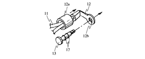
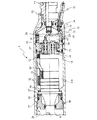
図1ないし図5は本発明の第1の実施の形態に係り、図1は超音波振動子の外観を示す外観図、図2は図1の振動子本体を分解・展開した分解図、図3は図1の振動子本体のABC断面を示す断面図、図4は図2のトランスデューサに設けられる端子の構成を示す構成図、図5は図1の超音波振動子の振動の分布と振動子本体の内部の位置関係を示す図である。
【0016】
(構成)
図1に示すように、本実施の形態の超音波振動子1は、この超音波振動子1を超音波振動させるための駆動電流を発生させる図示しないジェネレータに接続するプラグ2と、プラグ2からの駆動電流を振動子本体3に通電するコード4と、超音波振動子1を洗浄する時にプラグ2内部に水分が侵入することを防ぐ防水キャップ5とからなる。
【0017】
図2は図1の振動子本体3を分解した様子を示し、図3は図1の振動子本体3のABC断面を示す。
【0018】
図2及び図3に示すように、振動子本体3内部には、図示しないジェネレータからの駆動電流を超音波振動に変換するトランスデューサ10が設けられている。このトランスデューサ10には電線11の被覆が剥がされた一端が半田付されており、電線11の被覆が剥がされた他端は端子12に対して半田付されている。
【0019】
ここで、図4を用いて端子12付近の組立て方法を示す。端子12は板状の金属板を折り曲げた物であり、電線11を半田付した部分は絶縁のために熱収縮チューブ12aが被されている。電線11が半田付されてない他端には端子穴12bが加工してある。この端子穴12bに電極13を挿通した後、さらに図2に示すように、仕切り部材14に設けられた穴部15に挿通され、電極13のネジ部分にナット16をねじ込む。これにより、端子12および電極13は仕切り部材14に対して固定される。なお、電極13には、図4に示すように、気密を保つためのOリング17が設けられている。
【0020】
図2及び図3に示すように、コード4の被覆を剥いで露出した電線20は電極13に半田付されており、コード4の被覆端部は熱収縮チューブ21の内部の止めリング22により固定され、コード4が振動子本体3から不用意に抜けることを防いでいる。
【0021】
トランスデューサ10を内部に組み込むケーシング23には、予め気密を保つためのOリング24,0リング25が組付いたツナギ部材26が接着されている。トランスデューサ10におけるフランジ27に対し、ネジ部28側に、ゴム板29を接着剤などで貼りつけておく。
【0022】
トランスデューサ10、ナット16、仕切り部材14、電極13、端子12及び電線11のこれらの部組は、ケーシング23の開放端のネジ部28側からケーシング23内部に挿入される。この時、ツナギ部材26に設けられた穴部30に仕切り部材14がはまり込むようにする。尚、穴部30には2面幅部分31が加工してあり、仕切り部材14の2面幅部分31とかみ合うことで、仕切り部材14が不用意に回転することはない。
【0023】
さらに、気密を確保するパッキン32を仕切り部材14とツナギ部材26で挟み込み、仕切り部材14は図示されない治具を用いて気密確認用孔33に引っかけて2面幅部分31内部に引込み、仕切り部材14のネジ部分をナット34で締め上げる。ケーシング23にトランスデューサ10を固定するために、振幅を拡大するホーン部35側からパッキン36及びパッキンずれ防止用のワッシャ37を挿入し、固定部材38をネジ部28にねじ込む。
【0024】
外部との気密は予め固定部材38に組付けられたOリング39およびOリング40とパッキン36により確保される。気密検査の際には、気密確認用孔33に気密確認用のコネクタを組付け、水中で圧縮空気を送気し、気泡の有無で確認する。検査終了後、気密保持のためOリング41を装着した気密キャップ42をねじ込む。その後、短絡防止のために、ナット16、電極13をシール剤43により完全に密封する。
【0025】
内キャップ51、外キャップ52、Oリング53はコード4をあらかじめ通しており、Oリング54を組付けた内キャップ51をツナギ部材26にネジ止めし、さらに外キャップ52をツナギ部材26の外周部へ組付ける。コード4の断線防止のためオレドメ防止部材55を内キャップ51にねじ込むことで、振動子本体3は完成する。Oリング25及びOリング54は内キャップ51とツナギ部材26の隙間に水分が浸入することを防止し、そして、Oリング53は、コード4と内キャップ51の隙間から水分が浸入することを防止する。
【0026】
図5は振動の分布63と振動子本体3の内部の位置関係を示す。振動の節64はフランジ27に位置しており、振動の腹66はホーン部35の先端に、振動の腹65はトランスデューサ10の後端に位置する。各振動の腹は節64の1/4波長の位置である。
【0027】
(作用)
手術にて超音波振動子1を超音波凝固切開具の振動子として使用した後、超音波振動子1の単体に分解し、プラグ2に防水キャップ5をして体液などの汚れを洗浄する。洗浄完了後、オートクレーブ滅菌装置に投入する。
【0028】
オートクレーブ装置内部では、滅菌前工程として、滅菌庫内の空気を引いて陰圧をかける。次に滅菌工程として高圧蒸気を注入する。これにより振動子は滅菌される。通常は滅菌工程後に乾燥工程を経て滅菌装置より取り出されるが、手術中、急きょ滅菌が必要になった場合には、一連の工程の内、乾燥工程を省略することがある。
【0029】
乾燥工程を省略した場合には、コード4の外皮及びプラグ2から、コード4内部を経由して、振動子本体3の内部に浸入した蒸気による水分が完全には抜けない。
【0030】
しかしながら、振動子本体3内部を構成する隔壁部材としてツナギ部材26、仕切り部材14があり、また、パッキン32、電極13及び気密キャップ42に設けられたOリング17、41によって水分がトランスデューサ10にある内腔10a(図3参照)に浸入することはない。また、シール剤43により、電極13はシール絶縁されているため、短絡することはない。
【0031】
(効果)
このように本実施の形態では、手術中に急きょ行なう、乾燥工程を省略したオートクレーブ滅菌や、乾燥工程のないオートクレーブ装置しか持っていない病院でオートクレーブ滅菌を行ったとしても、トランスデューサ10にある内腔10a内部に水分が浸入することがないため、振動子の発振異常などがなく、通常通り手術に使用でき、手術時間の延長などを避けることができる。
【0032】
(第2の実施の形態)
図6は本発明の第2の実施の形態に係る振動子本体の軸方向の断面を示す断面図である。
【0033】
第2の実施の形態は、第1の実施の形態とほとんど同じであるので、異なる点のみ説明し、同一の構成には同じ符号をつけ説明は省略する。
【0034】
(構成)
本実施の形態の振動子本体3においては、図6に示すように、第1の実施の形態における外キャップ8を、電気メス接続コードを接続するための端子部72が設けらた外キャップ71に変更している。端子部72は外キャップ71に対してネジ込み固定されており、Oリング73、74により、水密が保たれている。端子部72の内部端は電線75の一端が半田付けされており、他端が13に半田付けされている。その他の構成は第1の実施の形態と同じである。
【0035】
(作用)
本実施の形態では、超音波凝固切開具を使用時に、電気メスを使用する際には、端子部72に電気メス接続コードを接続することで、電気メスとして使用することもできる。その他の作用は第1の実施の形態と同じである。
【0036】
(効果)
このように本実施の形態によれば、第1の実施の形態の効果に加えて、術中、電気メスを使用する際には、特に内視鏡下外科手術の際には電気メス用のプローブに代えることなく、本振動子の端子部72に接続コードを接続するだけでよいため、手術中の機器の交換がなくなるため、術者の手を煩わすことなく手術できる。
【0037】
(第3の実施の形態)
図7ないし図10は本発明の第3の実施の形態に係わり、図7は振動子本体の先端側外観を示す外観図、図8は図7の振動子本体の基端側外観を示す外観図、図9は図7の振動子本体を分解・展開した分解図、図10は図7の振動子本体の軸方向の断面を示す断面図である。
【0038】
第3の実施の形態は、第1の実施の形態とほとんど同じであるので、異なる点のみ説明し、同一の構成には同じ符号をつけ説明は省略する。
【0039】
(構成)
本実施の形態の振動子本体3では、図7に示すように、トランスデューサ10の振動振幅を拡大するホーン部35には、振動子本体3の軸方向中心に沿って貫通穴81が設けれらている。そして、図8に示すように、ホーン部35の部材がトランスデューサ10の後端に至るパイプ状の部材82と同一部品として構成されており、貫通穴81は振動子本体3の後端にあるパイプ状の吸引口金99の貫通穴である吸引管路98と同一軸の管路になっている。
【0040】
以下、本実施の形態の振動子本体3の構成を図9及び図10を用いて説明する。
【0041】
第1の実施の形態にて示した仕切り部材14に代わる本実施の形態の仕切り部材90の中心にはOリング91が組付いた貫通穴92が設けられており、貫通穴92にパイプ状の部材82が挿入されている。
【0042】
この状態でケーシング23内部に実施例1と同様にナット16、電極13、トランスデューサ10、仕切り部材90を挿入しナット34にて固定する。第1の実施の形態における内キャップ51に代わる、本実施の形態の内キャップ93を、図示しないネジでツナギ部材26に固定し、Oリング94を組付けたパイプ管路95のあるパイプ96を内キャップ93にネジ込み、仕切り部材90の貫通穴92に挿入固定する。Oリング97を組付けた吸引管路98のある吸引口金99は、第1の実施の形態における外キャップ52に代わる本実施の形態の外キャップ100にネジ込み固定されており、外キャップ100をツナギ部材26に固定する。コード4およびオレドメ防止部材55は、外キャップ100に対して偏心した位置でネジ込み固定されている。その他の構成は第1の実施の形態と同じである。
【0043】
(作用)
第1の実施の形態の作用に加えて、本実施の形態の振動子本体3には貫通穴が設けられているため、吸引口金99に図示しない吸引チューブを接続し、外部の吸引装置と組合わせることで、ホーン部35に取り付けた図示しない穴付プローブの先端から吸引した液体は貫通穴81からパイプ96,吸引管路98を経由して吸引チューブに至り、外へ排出できる。また、吸引口金99に送水用チューブを取り付けた場合には、生理食塩水が吸引管路98からパイプ96,貫通穴81、穴付プローブ先端(図示しない)へと至り、術野に生理食塩水などを送水できる。
【0044】
(効果)
このように本実施の形態によれば、超音波吸引装置の振動子ユニットとして使用しても第1の実施の形態の効果が得られる。超音波吸引装置は生体組織を乳化吸引でき、組織選択性の機能により、脈管類を残して、周辺組織を吸引できるため、手術時間を短縮できる。術野に必要に応じて生理食塩水などを散布できるため、手術が滞ることなく進められる。
【0045】
[付記]
(付記項1) 駆動電流を振動に変換するトランスデューサと、
基部にフランジ状の固定部を形成した前記振動の振幅を拡大するホーンと、
前記トランスデューサを覆うカバーと、
フランジ状の前記固定部と前記カバーの間にパッキンを配置して防水的に支持固定する支持固定部と、
前記駆動電流を供給する電源コードと、
前記駆動電流を発生させる外部の電源に対してコードを着脱するプラグと
からなる超音波振動子において、
前記カバー内部に、前記トランスデューサを囲う第1室と前記コードをカバー内に引込む第2室とを隔てる仕切り部材
を設けたことを特徴とする超音波振動子。
【0046】
(付記項2) 前記仕切り部材は、前記ホーンのフランジ状の前記固定部に存在する振動の節部から1/4波長以上離れた位置に設けた
ことを特徴とする付記項1に記載の超音波振動子。
【0047】
(付記項3) 前記仕切り部材は、
前記第1室と前記第2室と通ずる空間を閉鎖をする閉鎖部材と、
前記閉鎖部材を保持する保持端面と
からなることを特徴とする付記項2に記載の超音波振動子。
【0048】
(付記項4) 前記閉鎖部材と前記保持端面の間に、前記第1室と前記第2室との気密確保する気密保持手段を設けた
ことを特徴とする付記項3に記載の超音波振動子。
【0049】
(付記項5) 前記仕切り部材に、前記電源コードからの駆動電流を前記第2室から前記第1室へ供給する電気的接続部を設けた
ことを特徴とする付記項4に記載の超音波振動子。
【0050】
(付記項6) 前記電気的接続部と前記仕切り部材の間で気密を確保する気密保持手段を設けた
ことを特徴とする付記項5に記載の超音波振動子。
【0051】
(付記項7) 前記仕切り部材に気密確認用の確認孔を設けた
ことを特徴とする付記項6に記載の超音波振動子。
【0052】
(付記項8) 前記気密確認用の確認孔を閉鎖する閉鎖手段を着脱自在に設けた
ことを特徴とする付記項7に記載の超音波振動子。
【0053】
(付記項9) 前記トランスデューサの中心軸を貫く第1の管路と、前記閉鎖部材を貫く第2の管路とが同一軸上に配置された
ことを特徴とする付記項3または4に記載の超音波振動子。
【0054】
(付記項10) 前記仕切り部材に、前記電源コードからの駆動電流を前記第2室から前記第1室へ供給する電気的接続部を設けた
ことを特徴とする付記項9に記載の超音波振動子。
【0055】
(付記項11) 前記第2の管路は、前記第2室を貫く筒状部材と、前記閉鎖手段を貫く接続孔とからなり、
前記第1の管路と前記筒状部材とが前記接続孔の内部で同一軸に接続された
ことを特徴とする付記項10に記載の超音波振動子。
【0056】
(付記項12) 前記接続孔の円筒内面と前記第1の管路の円筒外面、および前記筒状部材の円筒外面の間に気密を確保するための気密保持手段を配置した
ことを特徴とする付記項11に記載の超音波振動子。
【0057】
(付記項13) 前記第2室内へ、超音波駆動用の電流以外の高周波電流を通電させるための第2の電流コードを引き込み、前記電気的接続部に接続した
ことを特徴とする付記項5に記載の超音波振動子。
【0058】
【発明の効果】
以上説明したように本発明の超音波振動子によれば、仕切り部材がカバー内部において、トランスデューサを囲う第1室とコードをカバー内に引込む第2室とを隔てるので、回転構造がない汎用性の高いシンプルな構造で、乾燥工程のないオートクレーブ滅菌しても、振動子ケーシング内部に水滴が侵入することを確実に防止することできるという効果がある。
【図面の簡単な説明】
【図1】本発明の第1の実施の形態に係る超音波振動子の外観を示す外観図
【図2】図1の振動子本体を分解・展開した分解図
【図3】図1の振動子本体のABC断面を示す断面図
【図4】図2のトランスデューサに設けられる端子の構成を示す構成図
【図5】図1の超音波振動子の振動の分布と振動子本体の内部の位置関係を示す図
【図6】第2の実施の形態に係る振動子本体の軸方向の断面を示す断面図
【図7】本発明の第3の実施の形態に係る振動子本体の先端側外観を示す外観図
【図8】図7の振動子本体の基端側外観を示す外観図
【図9】図7の振動子本体を分解・展開した分解図
【図10】図7の振動子本体の軸方向の断面を示す断面
【符号の説明】
1…超音波振動子
2…プラグ
3…振動子本体
4…コード
5…防水キャップ
10…トランスデューサ
11、20…電線
12…端子
12a、21…熱収縮チューブ
12b…端子穴
13…電極
14…仕切り部材
15…穴部
16、34…ナット
17、24、25、39、40、41、53、54…Oリング
22…止めリング
23…ケーシング
26…ツナギ部材
27…フランジ
28…ネジ部
29…ゴム板
30…穴部
31…2面幅部分
32、36…パッキン
33…気密確認用孔
35…ホーン部
37…ワッシャ
38…固定部材
42…気密キャップ
43…シール剤
51…内キャップ
52…外キャップ
55…オレドメ防止部材[0001]
TECHNICAL FIELD OF THE INVENTION
The present invention relates to an ultrasonic vibrator that generates a ultrasonic vibration by supplying a high-frequency current to a vibration element.
[0002]
[Prior art]
Generally, an ultrasonic surgical apparatus used for a surgical operation is configured such that various probes are attached to a device (vibrator) that generates high-frequency vibration by supplying a high-frequency current from a power supply device to a vibrating element, so that an abdominal cavity is obtained. This is possible with mirror surgery or open surgery.
[0003]
Such surgical devices must be sterile in order for the surgeon to directly operate the device by hand. Transducers for ultrasonic surgical devices are no exception, and it is essential that autoclave sterilization be possible.
[0004]
Such a vibrator has been proposed in, for example, US Pat. No. 5,395,240, Japanese Patent Publication No. Hei 7-106206, and Japanese Patent Application Laid-Open No. Hei 10-127655.
[0005]
[Problems to be solved by the invention]
Autoclave sterilization includes various types of autoclave sterilization methods by combining parameters such as time, pressure, and temperature in a vacuuming step, a sterilization step, a drying step, and the like.
[0006]
Ultrasonic transducers are not compatible with all these autoclave sterilization methods. Normally, the autoclave cycle is a cycle of evacuation, sterilization, and drying. However, if it is accidentally dropped on the floor during surgery, autoclaving may be performed urgently.
[0007]
In such a case, a cycle of evacuation and sterilization, in which the drying step is omitted to shorten the time, is performed. If the drying step is omitted, the infiltrated steam may not be completely removed inside the casing of the vibrator disclosed in Japanese Patent Publication No. 7-106206 and may accumulate as water droplets. When ultrasonic vibration is applied as it is, in a bolted Langevin type transducer (transducer), water droplets adhere between the electrodes sandwiching PZT, causing a short circuit (short circuit), and the conversion efficiency of the ultrasonic wave is reduced. there were.
[0008]
Further, in the case where autoclave sterilization is simply performed in a small medical institution, there is a case where only autoclave sterilization without a drying step is performed. In this case as well, water droplets may accumulate inside the oscillator casing. As a result, in the bolted Langevin-type oscillator (transducer), a short circuit occurs due to the adhesion of water droplets between the electrodes sandwiching PZT (lead zirconate titanate). However, the conversion efficiency of the ultrasonic vibration may decrease.
[0009]
The invention of US Pat. No. 5,395,241 is a magnetostrictive vibrator (transducer), so there is no problem even if the inside is intentionally sterilized by autoclave, but it is not easy to clean and the bolted Langevin type vibrator is reduced in terms of miniaturization of the vibrator. (Transducers) are much more advantageous.
[0010]
In the invention disclosed in Japanese Patent Application Laid-Open No. Hei 10-127655, when autoclave sterilization without a drying step is performed, steam does not enter the vibrator, so that the conversion efficiency of ultrasonic vibration does not decrease. However, since the O-ring is used for the rotary sliding portion, there is a possibility that the rotation cannot be performed smoothly, and there is a rotating electrical connection portion, so that electrical contact may be uncertain. In addition, since the internal structure of the vibrator is complicated, the weight increases and the outer diameter of the vibrator increases. From the viewpoint of the versatility of the vibrator, it is of course better that the structure of the vibrator is simple.
[0011]
The present invention has been made in view of the above circumstances. In a bolted Langevin type ultrasonic transducer (transducer), it has a simple structure with high versatility without a rotating structure, and is subjected to autoclave sterilization without a drying process. It is another object of the present invention to provide an ultrasonic vibrator that can reliably prevent water droplets from entering the vibrator casing.
[0012]
[Means for Solving the Problems]
An ultrasonic vibrator of the present invention includes a transducer that converts a drive current into vibration, a horn that forms a flange-shaped fixed portion at a base to increase the amplitude of the vibration, a cover that covers the transducer, and a flange-shaped cover. A support fixing portion for arranging a packing between the fixing portion and the cover in a waterproof and supporting manner , a power cord for supplying a drive current for supplying the transducer from an external power source into the cover, a plug releasably the power cord to the external power source to generate a current, and connected drive current electrical transmission means to said transducer, said drive current electrical transmission means, for electrically connecting the power cord conduction and the member, inside the cover, separate the second chamber to draw the power cord and the first chamber surrounding the transducer in the cover, and A partition member provided with holes for inserting the conductive member, characterized in that a, a gas-tight means provided in the conducting member.
[0014]
BEST MODE FOR CARRYING OUT THE INVENTION
Hereinafter, embodiments of the present invention will be described with reference to the drawings.
[0015]
(First Embodiment)
1 to 5 relate to a first embodiment of the present invention. FIG. 1 is an external view showing the appearance of an ultrasonic vibrator. FIG. 2 is an exploded view of the vibrator main body of FIG. 3 is a cross-sectional view showing an ABC cross section of the vibrator main body of FIG. 1, FIG. 4 is a configuration diagram showing a configuration of terminals provided on the transducer of FIG. 2, and FIG. 5 is a vibration distribution and vibration of the ultrasonic vibrator of FIG. It is a figure which shows the positional relationship inside a child main body.
[0016]
(Constitution)
As shown in FIG. 1, the
[0017]
2 shows an exploded view of the vibrator
[0018]
As shown in FIGS. 2 and 3, a
[0019]
Here, an assembling method near the terminal 12 will be described with reference to FIG. The terminal 12 is obtained by bending a plate-shaped metal plate, and a portion where the
[0020]
As shown in FIGS. 2 and 3, the
[0021]
A casing
[0022]
These sets of the
[0023]
Further, the packing 32 for ensuring airtightness is sandwiched between the
[0024]
The airtightness with the outside is ensured by the O-
[0025]
The
[0026]
FIG. 5 shows the distribution 63 of the vibration and the positional relationship inside the
[0027]
(Action)
After using the
[0028]
Inside the autoclave device, as a pre-sterilization step, negative pressure is applied by drawing air from the sterilization chamber. Next, high-pressure steam is injected as a sterilization step. Thus, the vibrator is sterilized. Usually, it is taken out of the sterilizer through a drying step after the sterilization step. However, if a rapid sterilization is required during the operation, the drying step may be omitted in a series of steps.
[0029]
If the drying step is omitted, the moisture from the steam that has entered the inside of the
[0030]
However, as the partition members constituting the inside of the vibrator
[0031]
(effect)
As described above, in the present embodiment, even if autoclave sterilization is performed quickly during surgery and the drying step is omitted, or autoclave sterilization is performed in a hospital having only an autoclave apparatus without a drying step, the lumen in the
[0032]
(Second embodiment)
FIG. 6 is a cross-sectional view showing an axial cross section of the vibrator main body according to the second embodiment of the present invention.
[0033]
Since the second embodiment is almost the same as the first embodiment, only different points will be described, and the same components will be denoted by the same reference numerals and description thereof will be omitted.
[0034]
(Constitution)
In the vibrator
[0035]
(Action)
In the present embodiment, when using the ultrasonic coagulation incision tool and using an electric scalpel, the electric knife can be used as an electric scalpel by connecting an electric scalpel connection cord to the
[0036]
(effect)
As described above, according to the present embodiment, in addition to the effects of the first embodiment, a probe for an electric scalpel is used during an operation, particularly when an electric scalpel is used, particularly during an endoscopic surgical operation. It is only necessary to connect a connection cord to the
[0037]
(Third embodiment)
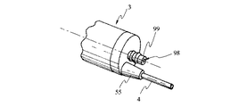
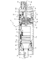
7 to 10 relate to a third embodiment of the present invention. FIG. 7 is an external view showing the distal end side appearance of the vibrator body, and FIG. 8 is an external view showing the base end side appearance of the vibrator body of FIG. FIG. 9 is an exploded view in which the vibrator main body of FIG. 7 is exploded and developed, and FIG. 10 is a cross-sectional view showing an axial cross section of the vibrator main body of FIG.
[0038]
Since the third embodiment is almost the same as the first embodiment, only different points will be described, and the same components will be denoted by the same reference numerals and description thereof will be omitted.
[0039]
(Constitution)
In the vibrator
[0040]
Hereinafter, the configuration of the transducer
[0041]
In the center of the
[0042]
In this state, the
[0043]
(Action)
In addition to the operation of the first embodiment, since the vibrator
[0044]
(effect)
As described above, according to the present embodiment, the effects of the first embodiment can be obtained even when used as a transducer unit of an ultrasonic suction device. The ultrasonic suction device can emulsify and aspirate a living tissue and, by the function of tissue selectivity, can aspirate surrounding tissues while leaving the vasculature, thereby shortening the operation time. Since the operation field can be sprayed with physiological saline as needed, the operation can be performed without delay.
[0045]
[Appendix]
(Additional Item 1) A transducer for converting a drive current into vibration,
A horn that expands the amplitude of the vibration, which has a flange-shaped fixing portion formed at the base,
A cover covering the transducer,
A support fixing portion for arranging packing between the flange-shaped fixing portion and the cover and supporting and fixing waterproofly,
A power cord for supplying the drive current;
An ultrasonic transducer comprising a plug for attaching and detaching a cord to an external power supply for generating the drive current,
An ultrasonic vibrator, wherein a partition member for separating a first chamber surrounding the transducer and a second chamber for drawing the cord into the cover is provided inside the cover.
[0046]
(Supplementary note 2) The ultra-compound according to
[0047]
(Additional Item 3) The partition member is
A closing member for closing a space communicating with the first chamber and the second chamber;
The ultrasonic vibrator according to
[0048]
(Additional Item 4) The ultrasonic vibration according to
[0049]
(Additional Item 5) The ultrasonic wave according to
[0050]
(Additional Item 6) The ultrasonic transducer according to Additional Item 5, wherein airtightness maintaining means for ensuring airtightness between the electrical connection portion and the partition member is provided.
[0051]
(Additional Item 7) The ultrasonic transducer according to Additional Item 6, wherein a check hole for checking airtightness is provided in the partition member.
[0052]
(Additional Item 8) The ultrasonic vibrator according to Additional Item 7, wherein a closing means for closing the confirmation hole for airtightness confirmation is provided detachably.
[0053]
(Additional Item 9) The
[0054]
(Additional Item 10) The ultrasonic wave according to Additional Item 9, wherein the partition member is provided with an electrical connection portion for supplying a drive current from the power cord from the second chamber to the first chamber. Vibrator.
[0055]
(Additional Item 11) The second conduit is formed of a cylindrical member penetrating the second chamber and a connection hole penetrating the closing means,
The ultrasonic transducer according to
[0056]
(Additional Item 12) An airtightness maintaining means for ensuring airtightness is arranged between the cylindrical inner surface of the connection hole, the cylindrical outer surface of the first conduit, and the cylindrical outer surface of the cylindrical member. The ultrasonic vibrator according to
[0057]
(Additional Item 13) An additional item 5 characterized in that a second current cord for supplying a high-frequency current other than an ultrasonic driving current is drawn into the second chamber and connected to the electrical connection portion. 4. The ultrasonic transducer according to
[0058]
【The invention's effect】
As described above, according to the ultrasonic transducer of the present invention, since the partition member separates the first chamber surrounding the transducer and the second chamber for drawing the cord into the cover inside the cover, the versatility without the rotary structure is provided. With a simple structure having a high water content, even if autoclave sterilization is performed without a drying step, there is an effect that water droplets can be reliably prevented from entering the inside of the vibrator casing.
[Brief description of the drawings]
FIG. 1 is an external view showing an external appearance of an ultrasonic vibrator according to a first embodiment of the present invention; FIG. 2 is an exploded view in which the vibrator main body in FIG. 1 is exploded and developed; FIG. FIG. 4 is a cross-sectional view showing an ABC cross section of the transducer main body. FIG. 4 is a structural view showing a configuration of terminals provided in the transducer of FIG. 2 FIG. 5 is a distribution of vibration of the ultrasonic transducer of FIG. FIG. 6 is a sectional view showing an axial section of a vibrator main body according to a second embodiment. FIG. 7 is a front end appearance of a vibrator main body according to a third embodiment of the present invention. FIG. 8 is an external view showing a base end side appearance of the vibrator main body of FIG. 7; FIG. 9 is an exploded view of the vibrator main body of FIG. Cross section showing the cross section in the axial direction of [Description of symbols]
DESCRIPTION OF
Claims (3)
基部にフランジ状の固定部を形成した前記振動の振幅を拡大するホーンと、
前記トランスデューサを覆うカバーと、
フランジ状の前記固定部と前記カバーの間にパッキンを配置して防水的に支持固定する支持固定部と、
前記トランスデューサに供給するための駆動電流を外部の電源から前記カバー内に供給する電源コードと、
前記駆動電流を発生させる前記外部の電源に対して前記電源コードを着脱するプラグと、
前記トランスデューサに接続された駆動電流電送手段と、
前記駆動電流電送手段と、前記電源コードとを電気的に接続する導通部材と、
前記カバー内部に配設された、前記トランスデューサを囲う第1室と前記電源コードをカバー内に引込む第2室とを隔て、かつ、前記導通部材を挿入する穴部を設けた仕切部材と、
前記導通部材に備えられた気密手段と、
を設けたことを特徴とする超音波振動子。A transducer for converting drive current into vibration,
A horn that expands the amplitude of the vibration, which has a flange-shaped fixing portion formed at the base,
A cover covering the transducer,
A support fixing portion for arranging packing between the flange-shaped fixing portion and the cover and supporting and fixing waterproofly,
A power cord for supplying a drive current for supplying to the transducer from an external power source into the cover ;
A plug releasably the power cord to the external power source for generating the driving current,
Drive current transmission means connected to the transducer,
A conductive member for electrically connecting the drive current transmitting means and the power cord,
Disposed within said cover, separates the second chamber to draw the power cord and the first chamber surrounding the transducer in the cover, and a partition member provided with holes for inserting the conductive member,
Airtight means provided on the conductive member,
An ultrasonic vibrator comprising:
Priority Applications (3)
| Application Number | Priority Date | Filing Date | Title |
|---|---|---|---|
| JP16139399A JP3556523B2 (en) | 1999-06-08 | 1999-06-08 | Ultrasonic transducer |
| US09/587,847 US6416525B1 (en) | 1999-06-08 | 2000-06-06 | Ultrasonic vibrator capable of infallably preventing drops of water from entering the inside of a casing of the vibrator even if autoclave sterilization without a drying process is performed |
| US10/152,362 US6827724B2 (en) | 1999-06-08 | 2002-05-20 | Ultrasonic vibrator capable of infallibly preventing drops of water from entering the inside of a casing of the vibrator even if autoclave sterilization without a drying process is performed |
Applications Claiming Priority (1)
| Application Number | Priority Date | Filing Date | Title |
|---|---|---|---|
| JP16139399A JP3556523B2 (en) | 1999-06-08 | 1999-06-08 | Ultrasonic transducer |
Publications (2)
| Publication Number | Publication Date |
|---|---|
| JP2000342597A JP2000342597A (en) | 2000-12-12 |
| JP3556523B2 true JP3556523B2 (en) | 2004-08-18 |
Family
ID=15734249
Family Applications (1)
| Application Number | Title | Priority Date | Filing Date |
|---|---|---|---|
| JP16139399A Expired - Fee Related JP3556523B2 (en) | 1999-06-08 | 1999-06-08 | Ultrasonic transducer |
Country Status (1)
| Country | Link |
|---|---|
| JP (1) | JP3556523B2 (en) |
Cited By (1)
| Publication number | Priority date | Publication date | Assignee | Title |
|---|---|---|---|---|
| WO2016022221A1 (en) * | 2014-08-04 | 2016-02-11 | Gyrus Acmi, Inc.. D.B.A. Olympus Surgical Technologies America | Lithotripter with improved sterilization time |
Families Citing this family (8)
| Publication number | Priority date | Publication date | Assignee | Title |
|---|---|---|---|---|
| JP4128496B2 (en) | 2003-07-30 | 2008-07-30 | オリンパス株式会社 | Ultrasonic treatment device |
| US8652397B2 (en) * | 2010-04-09 | 2014-02-18 | Southwire Company | Ultrasonic device with integrated gas delivery system |
| DK2556176T3 (en) | 2010-04-09 | 2020-05-04 | Southwire Co Llc | Ultrasonic degassing of molten metals |
| JP5149345B2 (en) * | 2010-08-05 | 2013-02-20 | 日本特殊陶業株式会社 | Ultrasonic transducer |
| CN102873016B (en) * | 2012-09-20 | 2014-08-20 | 张家港睿能科技有限公司 | Sealing switching device for ultrasonic transducer |
| BR112016011262B1 (en) | 2013-11-18 | 2021-05-18 | Southwire Company, Llc | ultrasonic device and method for reducing an amount of a dissolved gas and/or an impurity in a molten metal bath |
| US10233515B1 (en) | 2015-08-14 | 2019-03-19 | Southwire Company, Llc | Metal treatment station for use with ultrasonic degassing system |
| FR3077727B1 (en) * | 2018-02-12 | 2020-02-21 | Edap Tms France | SOURCE FOR PRODUCING ULTRASONIC WAVES WITH EXTERNAL THREAD |
-
1999
- 1999-06-08 JP JP16139399A patent/JP3556523B2/en not_active Expired - Fee Related
Cited By (1)
| Publication number | Priority date | Publication date | Assignee | Title |
|---|---|---|---|---|
| WO2016022221A1 (en) * | 2014-08-04 | 2016-02-11 | Gyrus Acmi, Inc.. D.B.A. Olympus Surgical Technologies America | Lithotripter with improved sterilization time |
Also Published As
| Publication number | Publication date |
|---|---|
| JP2000342597A (en) | 2000-12-12 |
Similar Documents
| Publication | Publication Date | Title |
|---|---|---|
| US6416525B1 (en) | Ultrasonic vibrator capable of infallably preventing drops of water from entering the inside of a casing of the vibrator even if autoclave sterilization without a drying process is performed | |
| US5211625A (en) | Ultrasonic treatment apparatus | |
| US5938633A (en) | Ultrasonic surgical devices | |
| JP2022087188A (en) | Ultrasonic surgical instrument with piezoelectric central lumen transducer | |
| JP2608692B2 (en) | Piezoelectric ultrasonic and electrosurgical handpieces | |
| WO2017013814A1 (en) | Ultrasound treatment tool and ultrasound treatment assembly | |
| US5626560A (en) | Diathermic hand-held instrument with an endoscopic probe | |
| JP3556523B2 (en) | Ultrasonic transducer | |
| CN103027718A (en) | Surgical instrument with ultrasonic waveguide defining a fluid lumen | |
| JP2009291776A (en) | Ultrasonic vibration apparatus | |
| WO2012132860A1 (en) | Ultrasound therapy device | |
| JP3390034B2 (en) | Ultrasound surgical handpiece | |
| JP4406261B2 (en) | Ultrasonic surgical device | |
| EP2904981B1 (en) | Treatment device | |
| US20030191390A1 (en) | Ultrasonic treatment apparatus | |
| US11369513B2 (en) | Low-cost disposable ultrasonic surgical handpiece | |
| JP3035442B2 (en) | Surgical equipment | |
| JP4245790B2 (en) | Ultrasonic treatment device | |
| JPH05305096A (en) | Medical hand piece | |
| JP3523810B2 (en) | Ultrasonic transducer unit | |
| JP3169989B2 (en) | Ultrasound therapy equipment | |
| JPH0595957A (en) | Ultrasonic therapeutic apparatus | |
| JP6033503B1 (en) | Ultrasonic treatment device and ultrasonic treatment assembly | |
| JPH0795985A (en) | Handpiece for surgical operation | |
| JPH10127655A (en) | Ultrasonic surgical operation equipment |
Legal Events
| Date | Code | Title | Description |
|---|---|---|---|
| TRDD | Decision of grant or rejection written | ||
| A01 | Written decision to grant a patent or to grant a registration (utility model) |
Free format text: JAPANESE INTERMEDIATE CODE: A01 Effective date: 20040427 |
|
| A61 | First payment of annual fees (during grant procedure) |
Free format text: JAPANESE INTERMEDIATE CODE: A61 Effective date: 20040512 |
|
| R151 | Written notification of patent or utility model registration |
Ref document number: 3556523 Country of ref document: JP Free format text: JAPANESE INTERMEDIATE CODE: R151 |
|
| FPAY | Renewal fee payment (event date is renewal date of database) |
Free format text: PAYMENT UNTIL: 20080521 Year of fee payment: 4 |
|
| FPAY | Renewal fee payment (event date is renewal date of database) |
Free format text: PAYMENT UNTIL: 20080521 Year of fee payment: 4 |
|
| FPAY | Renewal fee payment (event date is renewal date of database) |
Free format text: PAYMENT UNTIL: 20090521 Year of fee payment: 5 |
|
| FPAY | Renewal fee payment (event date is renewal date of database) |
Free format text: PAYMENT UNTIL: 20100521 Year of fee payment: 6 |
|
| FPAY | Renewal fee payment (event date is renewal date of database) |
Free format text: PAYMENT UNTIL: 20100521 Year of fee payment: 6 |
|
| FPAY | Renewal fee payment (event date is renewal date of database) |
Free format text: PAYMENT UNTIL: 20110521 Year of fee payment: 7 |
|
| FPAY | Renewal fee payment (event date is renewal date of database) |
Free format text: PAYMENT UNTIL: 20120521 Year of fee payment: 8 |
|
| FPAY | Renewal fee payment (event date is renewal date of database) |
Free format text: PAYMENT UNTIL: 20130521 Year of fee payment: 9 |
|
| FPAY | Renewal fee payment (event date is renewal date of database) |
Free format text: PAYMENT UNTIL: 20140521 Year of fee payment: 10 |
|
| S531 | Written request for registration of change of domicile |
Free format text: JAPANESE INTERMEDIATE CODE: R313531 |
|
| R350 | Written notification of registration of transfer |
Free format text: JAPANESE INTERMEDIATE CODE: R350 |
|
| LAPS | Cancellation because of no payment of annual fees |