JP3556413B2 - Image forming device - Google Patents
Image forming device Download PDFInfo
- Publication number
- JP3556413B2 JP3556413B2 JP27335196A JP27335196A JP3556413B2 JP 3556413 B2 JP3556413 B2 JP 3556413B2 JP 27335196 A JP27335196 A JP 27335196A JP 27335196 A JP27335196 A JP 27335196A JP 3556413 B2 JP3556413 B2 JP 3556413B2
- Authority
- JP
- Japan
- Prior art keywords
- transfer
- transfer material
- guide member
- image forming
- image
- Prior art date
- Legal status (The legal status is an assumption and is not a legal conclusion. Google has not performed a legal analysis and makes no representation as to the accuracy of the status listed.)
- Expired - Fee Related
Links
Images


Description
【0001】
【発明の属する技術分野】
本発明は複写機、ファクシミリ、プリンター等に応用される電子写真プロセスを用いた画像形成装置に関する。
【0002】
【従来の技術】
従来より電子写真プロセスを用いた画像形成装置が知られており、複写機、ファクシミリ、プリンター等として製品化されている。
図8に電子写真プロセスを用いた画像形成装置の構成例を簡略化して示す。図8において、図中符号1は像担持体としてのドラム状の感光体、2は帯電装置、3は原稿像の露光装置あるいはレーザー光を用いた光書込装置等からの光学的画像情報、4は現像装置、5は転写材の進入ガイド部材、6は転写紙やOHPシート等の転写材、7はコロナ方式の転写装置、8はワイヤを用いた除電・分離部材、9はクリーニング装置、10は除電用露光装置、11は搬送ガイド板、12は定着装置をそれぞれ示している。
【0003】
図8において、画像形成動作が開始されると、感光体1が図中の矢印方向に回転される。そして帯電装置2により感光体表面が一様帯電された後、光学的画像情報3が照射されて静電潜像が形成され、該静電潜像は現像装置4の現像剤中のトナーにより現像されて可視像化され、転写領域(感光体1と転写装置7の対向部)に至る。一方、上記の潜像形成及び現像の動作にタイミングを合わせて図示しない給紙装置から給紙された転写紙等の転写材6は、進入ガイド部材5に導かれて転写領域に送りこまれ、感光体1表面に密着した状態で転写装置7により裏面にトナーと逆極性の電荷を付与され、感光体1上の現像像(トナー像)が転写材6に転写される。転写後の転写材6は、除電・分離装置8によりその電荷が除去されて感光体表面より分離し、搬送ガイド板11に導かれて定着装置12に至り、定着装置12の加熱ローラ及び加圧ローラによりトナー像が転写材6に定着され、図示しない排紙部に排紙される。一方、転写後の感光体1はクリーニング装置9により残留トナーを除去され、除電用露光装置10にて除電される。以上のようにして1枚分の画像形成動作が終了し、多数枚の画像形成を行う場合は、同様の動作が繰り返し実行される。
【0004】
【発明が解決しようとする課題】
近年、電子写真プロセスを用いた画像形成装置において小型化、低コスト化が進み、それに伴い感光体等の像担持体やその他のユニットも小型化、低コスト化する必要がある。
例えば、図8に示すような構成の画像形成装置においては、小型化、低コスト化の一つの方法として、ドラム状の感光体1を小径化する(例えば、直径φを30mm以下にする)方法が上げられる。これにより従来の感光体よりも転写材のコシによる分離が行いやすくなるため、従来径の大きな感光体の時に使用されていた除電・分離チャージャーを廃止したり、除電・分離に針状の電極等を使用することが可能となり、除電・分離装置の小型化、低コスト化が実現できる。
【0005】
しかし、感光体1を小径化して転写材6が分離しやすくなるため、逆に転写のための充分なニップ幅をとることが難しくなり、従来のコロナ放電方式での転写性を安定化させるのが困難になってくる。
【0006】
そこで近年では、オゾン発生量低減の達成のためもあり、小径のドラム状感光体を用いた画像形成装置では、ローラやベルトタイプの接触方式の転写装置が多く使われるようになってきた。しかし、このような方式を採用することにより小型化は実現できるが、コロナ放電方式と比較するとコスト的にはまだまだ高いのが現状である。
【0007】
本発明は上記事情に鑑みなされたものであって、その目的(課題)は、小型・低コスト化を実現できる「φ30mm以下の小径の像担持体+非接触方式の転写装置」のシステムを採用した画像形成装置において、複雑な構成にすること無しに十分な転写ニップ幅を確保して安定した転写性を得ることである。
【0008】
【課題を解決するための手段】
上記目的を達成するため、本発明は、小径(例えば、直径φが30mm以下)の像担持体と、その表面に形成された現像像を転写材に転写するための非接触方式の転写装置と、転写終了後に像担持体より分離された転写材を定着装置まで案内・搬送するための搬送ガイド部材を備え、前記転写材は転写領域を通過して現像像を転写された後、像担持体表面から転写材自身のコシ及び自重により分離するように構成した画像形成装置において、転写終了後に像担持体表面から転写材自身のコシ及び自重により分離された転写材の先端が搬送ガイド部材または搬送ガイド部材に付設された他の部材に接触した後、該先端部の進行方向が上方に変更されるとともに、転写材が搬送ガイド部材の少なくとも一部で該接触位置よりも高い位置を搬送されるように搬送ガイド部材を構成した。
【0009】
また、本発明は、前記搬送ガイド部材の転写材搬送方向上流側である転写装置側に下向きの傾斜部を一体に設けるとともに、転写材先端がこの傾斜部に進入するように配置した。
【0010】
さらに本発明は、前記傾斜部の転写側自由端から延ばした水平延長線が転写装置のケーシング内部に直接進入することがないように搬送ガイド部材を構成・配置したことを特徴とするものである。
【0011】
【発明の実施の形態】
以下、本発明の実施の形態を図示の実施例に基づいて詳細に説明する。
【0012】
図1は本発明の一実施例を示す画像形成装置の概略構成図である。
図1において、図中符号1は像担持体としてのドラム状の感光体、2は帯電装置、3は原稿像の露光装置あるいはレーザー光を用いた光書込装置等からの光学的画像情報、4は現像装置、5は転写材の進入ガイド部材、6は転写材、7はコロナ方式の転写装置、7aはケーシング、7bはワイヤ電極、9はクリーニング装置、10は除電用露光装置、11’は板状の搬送ガイド部材(以下、搬送ガイド板と称す)、12は定着装置をそれぞれ示しており、図8に示した画像形成装置と同符号のユニットは同じものを表しており画像形成動作も同様であるが、本実施例では、像担持体であるドラム状感光体1の直径φを30mmとし、従来装置よりも小径化している。また、感光体1を小径化したことにより、除電・分離部材を省略している。さらに本実施例では、搬送ガイド板11’の転写装置側(転写材搬送方向上流側)に、転写材進行方向斜め上方に延びる板状のマイラ部材13が設けられている。
【0013】
図1において、画像形成動作が開始されると、感光体1が図中の矢印方向に回転される。そして帯電装置2により感光体表面が一様帯電された後、光学的画像情報3が照射されて静電潜像が形成され、該静電潜像は現像装置4の現像剤中のトナーにより現像されて可視像化され、転写領域(感光体1と転写装置7の対向部でワイヤ電極7bによる放電領域)に至る。一方、上記の潜像形成及び現像の動作にタイミングを合わせて図示しない給紙装置から給紙された転写紙等の転写材6は、進入ガイド部材5に導かれて感光体1表面に到達し、感光体1表面に密着した状態で転写装置7によりトナーと逆極性の転写電荷を受ける転写領域に導かれる。そして転写材6は転写領域を通過して現像像(トナー像)を転写された後、感光体1表面から転写材自身のコシ及び自重により分離する。それから転写材6の先端は、図2に示すように搬送ガイド板11’に付設されたマイラ部材13に到達して接触し、マイラ部材13により進行方向を斜め上方に変えられる。そして転写材6の先端が図3に示すようにマイラ部材13の上を通過することにより、転写材6は上記先端部の接触位置よりも高い位置を搬送されていく。
【0014】
ここで転写材6の先端が搬送ガイド板11’のマイラ部材13に到達するまでは、転写材6と感光体1の分離点は図2に示すA点付近となっているが、転写材6の先端がマイラ部材13を上がっていくに連れて分離点は感光体回転方向下流側に変化し、図3のような状態では分離点はB点付近となる。すなわち、分離点がA点付近からB点付近に変わることにより転写に必要なニップ幅が増加するため、転写性が低下する低湿環境や両面時(転写材の両面に画像形成を行う時)でも安定した転写性を確保することができるようになる。
【0015】
次に、図4は本発明の別の実施例を示す画像形成装置の概略構成図である。
図4において図1と同符号を付したユニットは同じものであり、画像形成動作も同様である。本実施例の画像形成装置では図1に示した搬送ガイド板のマイラ部材13は設けられていないが、搬送ガイド板11’’の転写側が斜め下方に向けて折り曲げられており、傾斜部14を構成している。
【0016】
図4に示す画像形成装置においては、図1を用いた上記説明と同様に転写材6は転写領域を通過して現像像(トナー像)を転写された後、感光体1表面から転写材自身のコシ及び自重により分離する。そして感光体1より分離した転写材6の先端は、図5に示すように搬送ガイド板11’’の傾斜部14に接触し、該傾斜部14により進行方向を上方に変えられる。それから転写材6の先端は傾斜部14に沿って上方に進んだ後、図6に示すように、上記先端部の接触位置よりも高い位置にある搬送ガイド板11’’の平行部分を搬送されて定着装置12まで案内される。
【0017】
本実施例の場合も、搬送ガイド板11’’の傾斜部14によって転写材6の分離点が図5に示すA点から図6に示すB点に変わるため、転写のためのニップ幅が増加し、転写性が低下する低湿環境や両面時でも安定した転写性を確保することができる。
【0018】
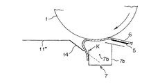
次に、図7は本発明の別の実施例を示す画像形成装置の構成及び動作の説明図である。
図7において図4と同符号を付したユニットは同じものであり、画像形成動作も同様であるが、本実施例では、搬送ガイド板11’’の傾斜部14の転写側自由端から延ばした水平延長線が転写装置7のケーシング7a内部に直接進入することがないように搬送ガイド板11’’を構成・配置したものである。
【0019】
すなわち図7に示すように、搬送ガイド板11’’の傾斜部14は、その延長線(図中破線で示す)が必ず転写装置7のケーシング7a内部に直接進入することがないように(ケーシング7aの端部Kより下側でケーシングの出口側の面と交差するように)構成・配置されているため、ユーザーが規格外や大きくカールしている転写材6を使用した場合に、転写材6が誤って傾斜部14の下側に進んでしまった場合でも、転写材6がケーシング7aの内部に進入することがないため、転写装置7内部のワイヤ電極7bの位置をずらしてしまったり、破損したりすることがない。
【0020】
ここで、図7に示す構成・配置の搬送ガイド板11’’を用いた画像形成装置におけるベタ部転写性の実験結果を、図8に示す従来タイプの搬送ガイド板11を用いた画像形成装置におけるベタ部転写性の実験結果と比較して下記の表1に示した。
尚、この場合の画像形成装置の構成は、ドラム状感光体1の直径φ30mm、感光体1の線速90mm/secとし、現像装置4には乾式2成分現像方式を用いた。また、転写材6としては、リコー製Type6200紙を使用した。
また、ベタ部転写性は、環境(温度/湿度)条件を変えて、転写紙の表面にベタ画像を転写する場合と、転写紙の両面にベタ画像を形成する際の裏面側の転写の場合について実験した。
【0021】
【表1】

表1の結果より明らかなように、本発明による画像形成装置では、φ30mm以下の小径の感光体1を用いた場合にも、搬送ガイド板11’’の転写装置側に設けた傾斜部14により、転写のためのニップ幅を稼ぐことができるので、低湿環境や両面時でも安定した転写性を得ることができる。
尚、上記の実施例ではワイヤ電極方式の転写装置を用いて説明を行ったが、針状電極等の非接触転写装置を用いた場合にも本発明が有効であることは言うまでもない。
【0023】
【発明の効果】
以上説明したように、本発明の画像形成装置においては、転写終了後に像担持体表面から転写材自身のコシ及び自重により分離された転写材の先端が搬送ガイド部材または搬送ガイド部材に付設された他の部材に接触した後、該先端部の進行方向が上方に変更されるとともに、転写材が搬送ガイド部材の少なくとも一部で該接触位置よりも高い位置を搬送されるように搬送ガイド部材を構成したことにより、小径(例えばφ30mm以下)の像担持体を用いた場合にも、転写のためのニップ幅を稼ぐことができるので、低湿環境や両面時でも安定した転写性を確保することができる。
【0024】
そして本発明の画像形成装置においては、前記の構成に加えて、搬送ガイド部材の転写材搬送方向上流側である転写装置側に下向きの傾斜部を一体に設けるとともに、転写材先端がこの傾斜部に進入するように配置したことにより、搬送ガイド部材の水平搬送部と進行方向変更部(傾斜部)を一体に形成することができるので、コストダウンを図ることができる。
【0025】
さらに本発明の画像形成装置においては、前記の構成に加えて、前記傾斜部の転写側自由端から延ばした水平延長線が転写装置のケーシング内部に直接進入することがないように搬送ガイド部材を構成・配置したことにより、転写材が誤って傾斜部の下側に進んでしまった場合でも、転写材が転写装置のケーシング内部に進入することがないため、転写装置の破損を防止することができる。
【図面の簡単な説明】
【図1】本発明の一実施例を示す画像形成装置の概略構成図である。
【図2】図1に示す画像形成装置における転写材搬送動作の説明図である。
【図3】図1に示す画像形成装置における転写材搬送動作の説明図である。
【図4】
本発明の別の実施例を示す画像形成装置の概略構成図である。
【図5】
図4に示す画像形成装置における転写材搬送動作の説明図である。
【図6】
図4に示す画像形成装置における転写材搬送動作の説明図である。
【図7】
本発明の別の実施例を示す画像形成装置の構成及び動作の説明図である。
【図8】
従来の画像形成装置の構成例を示す概略構成図である。
【符号の説明】
1:感光体(像担持体)
2:帯電装置
4:現像装置
5:進入ガイド部材
6:転写材
7:転写装置
7a:ケーシング
7b:ワイヤ電極
9:クリーニング装置
10:除電用露光装置
11’,11’’:搬送ガイド板(搬送ガイド部材)
12:定着装置
13:マイラ部材
14:傾斜部[0001]
TECHNICAL FIELD OF THE INVENTION
The present invention relates to an image forming apparatus using an electrophotographic process applied to a copying machine, a facsimile, a printer, and the like.
[0002]
[Prior art]
2. Description of the Related Art Conventionally, an image forming apparatus using an electrophotographic process has been known, and has been commercialized as a copier, a facsimile, a printer, or the like.
FIG. 8 shows a simplified configuration example of an image forming apparatus using an electrophotographic process. In FIG. 8,
[0003]
8, when the image forming operation is started, the
[0004]
[Problems to be solved by the invention]
In recent years, image forming apparatuses using an electrophotographic process have been reduced in size and cost, and accordingly, it has been necessary to reduce the size and cost of image carriers such as photoconductors and other units.
For example, in an image forming apparatus having a configuration as shown in FIG. 8, as one method of reducing the size and cost, a method of reducing the diameter of the drum-shaped photoconductor 1 (for example, reducing the diameter φ to 30 mm or less). Is raised. This makes it easier to separate the transfer material by stiffness than with conventional photoconductors, eliminating the need for a static elimination / separation charger that was used for photoconductors with large diameters, and needle-like electrodes for static elimination / separation. Can be used, and miniaturization and cost reduction of the static elimination / separation device can be realized.
[0005]
However, since the diameter of the
[0006]
Therefore, in recent years, in order to achieve a reduction in the amount of generated ozone, a roller or belt-type contact type transfer device has come into wide use in an image forming apparatus using a small-diameter drum-shaped photoconductor. However, although the size can be reduced by adopting such a method, the cost is still higher than the corona discharge method at present.
[0007]
The present invention has been made in view of the above circumstances, and an object (problem) of the present invention is to employ a system of “a small-diameter image carrier having a diameter of 30 mm or less + a non-contact transfer device” capable of realizing a reduction in size and cost. In the image forming apparatus described above, a sufficient transfer nip width is secured without obtaining a complicated configuration to obtain stable transferability.
[0008]
[Means for Solving the Problems]
In order to achieve the above object, the present invention provides an image carrier having a small diameter (for example, having a diameter φ of 30 mm or less) and a non-contact type transfer device for transferring a developed image formed on the surface thereof to a transfer material. A transfer guide member for guiding and transporting the transfer material separated from the image carrier to the fixing device after the transfer is completed, wherein the transfer material passes through a transfer area to transfer a developed image, and then the image carrier is In an image forming apparatus configured to be separated from the surface by the stiffness of the transfer material itself and its own weight, the end of the transfer material separated from the surface of the image carrier by the stiffness of the transfer material itself and its own weight after the transfer is completed, the transfer guide member or the transfer member After contacting another member attached to the guide member, the advancing direction of the tip is changed upward, and the transfer material is conveyed at a position higher than the contact position by at least a part of the conveyance guide member. To constitute a conveyance guide member so.
[0009]
Further, in the present invention, a downward inclined portion is integrally provided on the transfer device side, which is an upstream side of the transport guide member in the transfer material transport direction, and the transfer material tip is arranged so as to enter the inclined portion .
[0010]
Further, the present invention is characterized in that the transport guide member is configured and arranged so that a horizontal extension line extending from the transfer-side free end of the inclined portion does not directly enter the inside of the casing of the transfer device. You.
[0011]
BEST MODE FOR CARRYING OUT THE INVENTION
Hereinafter, embodiments of the present invention will be described in detail with reference to the illustrated examples.
[0012]
FIG. 1 is a schematic configuration diagram of an image forming apparatus showing one embodiment of the present invention.
In FIG. 1,
[0013]
In FIG. 1, when an image forming operation is started, the
[0014]
Here, until the leading end of the
[0015]
Next, FIG. 4 is a schematic configuration diagram of an image forming apparatus showing another embodiment of the present invention.
In FIG. 4, units denoted by the same reference numerals as in FIG. 1 are the same, and the image forming operation is also the same. Although the
[0016]
In the image forming apparatus shown in FIG. 4, the
[0017]
Also in the case of the present embodiment, the separation point of the
[0018]
Next, FIG. 7 is an explanatory diagram of the configuration and operation of an image forming apparatus according to another embodiment of the present invention.
In FIG. 7, the units denoted by the same reference numerals as those in FIG. 4 are the same, and the image forming operation is also the same. However, in this embodiment, the unit is extended from the transfer-side free end of the
[0019]
That is, as shown in FIG. 7, the
[0020]
Here, an experimental result of the solid portion transferability in the image forming apparatus using the
In this case, the configuration of the image forming apparatus was such that the diameter of the drum-shaped
The solid part transferability is determined by changing the environment (temperature / humidity) conditions to transfer a solid image to the front surface of the transfer paper, or to the transfer of the back surface when forming a solid image on both sides of the transfer paper. Was tested.
[0021]
[Table 1]
As is clear from the results shown in Table 1, in the image forming apparatus according to the present invention, even when the
Although the above embodiment has been described using a wire electrode type transfer device, it goes without saying that the present invention is also effective when a non-contact transfer device such as a needle electrode is used.
[0023]
【The invention's effect】
As described above, in the image forming apparatus of the present invention , the end of the transfer material separated from the surface of the image carrier by the stiffness and its own weight of the transfer material after the transfer is completed is attached to the transfer guide member or the transfer guide member. After contacting another member, the traveling direction of the leading end is changed upward, and the transfer guide member is moved so that the transfer material is conveyed at a position higher than the contact position by at least a part of the transfer guide member. With this configuration, even when an image carrier having a small diameter (for example, φ30 mm or less) is used, the nip width for transfer can be increased, so that stable transferability can be ensured even in a low-humidity environment or on both sides. it can.
[0024]
In the image forming apparatus of the present invention , in addition to the above configuration, a downward inclined portion is integrally provided on the transfer device side, which is an upstream side of the transport guide member in the transfer material transport direction, and the tip of the transfer material is formed by the inclined portion. by arranging such that enters, since the traveling direction changing unit horizontal conveying portion of the conveyance guide member (inclined portion) can be formed integrally, the cost can be reduced.
[0025]
Further, in the image forming apparatus of the present invention, in addition to the above, the conveyance guide member so as not to horizontal extension line extended from the transfer-side free end of the inclined portion enters directly into the casing inside of the transfer device With the configuration and arrangement, even if the transfer material accidentally advances to the lower side of the inclined portion, the transfer material does not enter the inside of the casing of the transfer device, thereby preventing damage to the transfer device. it can.
[Brief description of the drawings]
FIG. 1 is a schematic configuration diagram of an image forming apparatus showing one embodiment of the present invention.
FIG. 2 is an explanatory diagram of a transfer material transport operation in the image forming apparatus shown in FIG.
FIG. 3 is an explanatory diagram of a transfer material transport operation in the image forming apparatus shown in FIG. 1;
FIG. 4
FIG. 9 is a schematic configuration diagram of an image forming apparatus showing another embodiment of the present invention.
FIG. 5
FIG. 5 is an explanatory diagram of a transfer material transport operation in the image forming apparatus shown in FIG. 4.
FIG. 6
FIG. 5 is an explanatory diagram of a transfer material transport operation in the image forming apparatus shown in FIG. 4.
FIG. 7
FIG. 7 is an explanatory diagram of a configuration and operation of an image forming apparatus according to another embodiment of the present invention.
FIG. 8
FIG. 9 is a schematic configuration diagram illustrating a configuration example of a conventional image forming apparatus.
[Explanation of symbols]
1: Photoconductor (image carrier)
2: Charging device 4: Developing device 5: Entry guide member 6: Transfer material 7:
12: fixing device 13: mylar member 14: inclined portion
Claims (1)
転写終了後に像担持体表面から転写材自身のコシ及び自重により分離された転写材の先端が搬送ガイド部材または搬送ガイド部材に付設された他の部材に接触した後、該先端部の進行方向が上方に変更されるとともに、転写材が搬送ガイド部材の少なくとも一部で該接触位置よりも高い位置を搬送されるように搬送ガイド部材を構成し、前記搬送ガイド部材の転写材搬送方向上流側である転写装置側に下向きの傾斜部を一体に設けるとともに、転写材先端がこの傾斜部に進入するように配置し、前記傾斜部の転写側自由端から延ばした水平延長線が転写装置のケーシング内部に直接進入することがないように搬送ガイド部材を構成・配置したことを特徴とする画像形成装置。A small-diameter image carrier, a non-contact transfer device for transferring a developed image formed on the surface of the image carrier to a transfer material, and a transfer device separated from the image carrier after transfer is guided and transported to a fixing device. The transfer material passes through a transfer area to transfer a developed image, and then is separated from the surface of the image carrier by the stiffness and weight of the transfer material itself. ,
After the end of the transfer, the tip of the transfer material separated from the surface of the image carrier by the stiffness of the transfer material itself and its own weight comes into contact with the transport guide member or another member attached to the transport guide member, and then the traveling direction of the tip portion is changed. The transfer guide member is configured so that the transfer material is conveyed at a position higher than the contact position in at least a part of the transfer guide member while being changed upward, and the transfer guide member is disposed upstream of the transfer guide member in the transfer material transfer direction. A downward inclined portion is integrally provided on a certain transfer device side, the leading end of the transfer material is arranged so as to enter the inclined portion, and a horizontal extension line extending from the free end of the inclined portion on the transfer side is inside the casing of the transfer device. An image forming apparatus , wherein a transport guide member is configured and arranged so as not to directly enter the image forming apparatus.
Priority Applications (1)
| Application Number | Priority Date | Filing Date | Title |
|---|---|---|---|
| JP27335196A JP3556413B2 (en) | 1996-09-19 | 1996-10-16 | Image forming device |
Applications Claiming Priority (3)
| Application Number | Priority Date | Filing Date | Title |
|---|---|---|---|
| JP8-248235 | 1996-09-19 | ||
| JP24823596 | 1996-09-19 | ||
| JP27335196A JP3556413B2 (en) | 1996-09-19 | 1996-10-16 | Image forming device |
Publications (2)
| Publication Number | Publication Date |
|---|---|
| JPH10149032A JPH10149032A (en) | 1998-06-02 |
| JP3556413B2 true JP3556413B2 (en) | 2004-08-18 |
Family
ID=26538670
Family Applications (1)
| Application Number | Title | Priority Date | Filing Date |
|---|---|---|---|
| JP27335196A Expired - Fee Related JP3556413B2 (en) | 1996-09-19 | 1996-10-16 | Image forming device |
Country Status (1)
| Country | Link |
|---|---|
| JP (1) | JP3556413B2 (en) |
-
1996
- 1996-10-16 JP JP27335196A patent/JP3556413B2/en not_active Expired - Fee Related
Also Published As
| Publication number | Publication date |
|---|---|
| JPH10149032A (en) | 1998-06-02 |
Similar Documents
| Publication | Publication Date | Title |
|---|---|---|
| JPH0577575B2 (en) | ||
| JP3569424B2 (en) | Image forming device | |
| JPH0741204A (en) | Image forming device | |
| JP2006133377A (en) | Image forming apparatus | |
| JP3576894B2 (en) | Sheet member conveying device in image forming apparatus | |
| JP3556413B2 (en) | Image forming device | |
| JP2008007329A (en) | Image forming device | |
| US6278859B1 (en) | Image forming apparatus with aligned transfer conveying units | |
| JP2005289644A (en) | Image forming device | |
| JP3578980B2 (en) | Transfer material separating mechanism and image forming apparatus provided with the same | |
| JP2000229748A (en) | Picture image formation device | |
| JP2002251087A (en) | Image forming device | |
| JP6163362B2 (en) | Image forming apparatus | |
| JP4639848B2 (en) | Image forming apparatus | |
| JP3684350B2 (en) | Separation device | |
| JP2006243001A (en) | Image forming apparatus | |
| JPH0478994B2 (en) | ||
| JP2535025Y2 (en) | Recording paper transport device | |
| JP2005084213A (en) | Image forming apparatus | |
| JP2006133329A (en) | Image forming apparatus | |
| JPS6090372A (en) | Transfer paper separating device | |
| JP2002154699A (en) | Image forming device | |
| JP3410805B2 (en) | Image forming device | |
| JPH03131884A (en) | Transfer device of image forming equipment | |
| JP2008129209A (en) | Image forming apparatus |
Legal Events
| Date | Code | Title | Description |
|---|---|---|---|
| A521 | Written amendment |
Free format text: JAPANESE INTERMEDIATE CODE: A523 Effective date: 20040108 |
|
| A131 | Notification of reasons for refusal |
Free format text: JAPANESE INTERMEDIATE CODE: A131 Effective date: 20040210 |
|
| A521 | Written amendment |
Free format text: JAPANESE INTERMEDIATE CODE: A523 Effective date: 20040409 |
|
| TRDD | Decision of grant or rejection written | ||
| A01 | Written decision to grant a patent or to grant a registration (utility model) |
Free format text: JAPANESE INTERMEDIATE CODE: A01 Effective date: 20040511 |
|
| A61 | First payment of annual fees (during grant procedure) |
Free format text: JAPANESE INTERMEDIATE CODE: A61 Effective date: 20040512 |
|
| R150 | Certificate of patent (=grant) or registration of utility model |
Free format text: JAPANESE INTERMEDIATE CODE: R150 |
|
| FPAY | Renewal fee payment (prs date is renewal date of database) |
Free format text: PAYMENT UNTIL: 20080521 Year of fee payment: 4 |
|
| FPAY | Renewal fee payment (prs date is renewal date of database) |
Free format text: PAYMENT UNTIL: 20090521 Year of fee payment: 5 |
|
| FPAY | Renewal fee payment (prs date is renewal date of database) |
Free format text: PAYMENT UNTIL: 20100521 Year of fee payment: 6 |
|
| LAPS | Cancellation because of no payment of annual fees |