JP3555641B2 - Release agent supply member, release agent supply device, and fixing device using the same - Google Patents
Release agent supply member, release agent supply device, and fixing device using the same Download PDFInfo
- Publication number
- JP3555641B2 JP3555641B2 JP28373896A JP28373896A JP3555641B2 JP 3555641 B2 JP3555641 B2 JP 3555641B2 JP 28373896 A JP28373896 A JP 28373896A JP 28373896 A JP28373896 A JP 28373896A JP 3555641 B2 JP3555641 B2 JP 3555641B2
- Authority
- JP
- Japan
- Prior art keywords
- release agent
- liquid level
- supply member
- agent supply
- tank
- Prior art date
- Legal status (The legal status is an assumption and is not a legal conclusion. Google has not performed a legal analysis and makes no representation as to the accuracy of the status listed.)
- Expired - Lifetime
Links
Images


Classifications
-
- G—PHYSICS
- G03—PHOTOGRAPHY; CINEMATOGRAPHY; ANALOGOUS TECHNIQUES USING WAVES OTHER THAN OPTICAL WAVES; ELECTROGRAPHY; HOLOGRAPHY
- G03G—ELECTROGRAPHY; ELECTROPHOTOGRAPHY; MAGNETOGRAPHY
- G03G15/00—Apparatus for electrographic processes using a charge pattern
- G03G15/20—Apparatus for electrographic processes using a charge pattern for fixing, e.g. by using heat
- G03G15/2003—Apparatus for electrographic processes using a charge pattern for fixing, e.g. by using heat using heat
- G03G15/2014—Apparatus for electrographic processes using a charge pattern for fixing, e.g. by using heat using heat using contact heat
- G03G15/2017—Structural details of the fixing unit in general, e.g. cooling means, heat shielding means
- G03G15/2025—Structural details of the fixing unit in general, e.g. cooling means, heat shielding means with special means for lubricating and/or cleaning the fixing unit, e.g. applying offset preventing fluid
-
- G—PHYSICS
- G03—PHOTOGRAPHY; CINEMATOGRAPHY; ANALOGOUS TECHNIQUES USING WAVES OTHER THAN OPTICAL WAVES; ELECTROGRAPHY; HOLOGRAPHY
- G03G—ELECTROGRAPHY; ELECTROPHOTOGRAPHY; MAGNETOGRAPHY
- G03G2215/00—Apparatus for electrophotographic processes
- G03G2215/20—Details of the fixing device or porcess
- G03G2215/2093—Release agent handling devices
-
- Y—GENERAL TAGGING OF NEW TECHNOLOGICAL DEVELOPMENTS; GENERAL TAGGING OF CROSS-SECTIONAL TECHNOLOGIES SPANNING OVER SEVERAL SECTIONS OF THE IPC; TECHNICAL SUBJECTS COVERED BY FORMER USPC CROSS-REFERENCE ART COLLECTIONS [XRACs] AND DIGESTS
- Y10—TECHNICAL SUBJECTS COVERED BY FORMER USPC
- Y10S—TECHNICAL SUBJECTS COVERED BY FORMER USPC CROSS-REFERENCE ART COLLECTIONS [XRACs] AND DIGESTS
- Y10S118/00—Coating apparatus
- Y10S118/01—Anti-offset
Description
【0001】
【発明の属する技術分野】
本発明は、被塗布体に離型剤を供給する離型剤供給部材、離型剤供給装置およびそれを用いた定着装置に関する。
【0002】
【従来の技術】
記録材上に形成されたトナー像を、熱ローラと加圧ローラにより加熱加圧して、記録材上に定着させる定着装置においては、熱ローラ表面に離型剤を塗布し、熱ローラとトナー像の相互の離型性を向上させる配慮が一般になされている。
【0003】
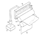
この種の定着装置に用いる離型剤供給装置については従来から種々提案がなされているが、その一形態として、図6に示す様に、離型剤を収容する離型剤タンク17と、離型剤タンク17内の離型剤を汲み上げるポンプ18と、離型剤タンク17から汲み上げられた離型剤を吐出する離型剤吐出部19aを備えた離型剤供給部材19と、離型剤供給部材19の上面を流れ降りてくる離型剤20を受け取る離型剤塗布ローラ14により構成したものが知られている。
【0004】
本構成において、離型剤20はタンク17からポンプ18により供給される。ポンプ18により汲み上げられた離型剤20は、離型剤供給部材19に設けられた多数の貫通穴からなる離型剤吐出部19aから吐出する。吐出した離型剤20は塗布ローラ14の回転により拭い取られ、塗布ローラ14表面に転移した離型剤20は熱ローラ11a表面に塗布される。
【0005】
【発明が解決しようとする課題】
ところで、上記従来構成の場合には、熱ローラ11aに離型剤20を供給する際に、離型剤吐出部19aから吐出した離型剤20が図7に示す様に筋状に流れ降りてくるので、離型剤20の液面は図8に示す様に各離型剤吐出部19a間のピッチによる凹凸をなしたり、離型剤の流路が定まらないために数本の離型剤の筋が合流して一本の筋になってしまう等、熱ローラ11aの軸方向における離型剤の塗布量にむらを発生させたりしていた。
【0006】
離型剤の塗布量が不均一な状態で定着工程が行われると、離型剤の塗布量が過剰の部位においては定着後のトナー像に光沢差が生じたりする。また、離型剤の塗布量が不足の部位においては熱ロール11a表面での適切な離型性を確保できないので、トナー像が熱ローラ11aへ付着する、いわゆるオフセット現象が生じたりして印刷品質不良の問題を引き起こしていた。
【0007】
本発明の目的は、被塗布体に離型剤を均一に供給することが可能な離型剤供給部材および離型剤供給装置を得ることにある。
【0008】
また、本発明の他の目的は、被塗布体に離型剤を均一に供給し、印刷品質の安定した定着装置を得ることにある。
【0009】
【課題を解決するための手段】
上記の目的は、離型剤供給部材を、離型剤を吐出する離型剤吐出部と、該吐出部から吐出された離型剤の流路をなすとともに、離型剤の移行方向へ進むにつれて分岐した溝部と、前記溝部に供給された離型剤の液面を均一にする液面整え部とで構成することにより達成される。
【0010】
【発明の実施の形態】
以下、本発明の実施例を図面を参照して説明する。
【0011】
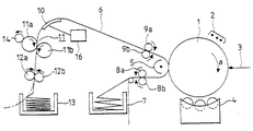
図5において、符号1は電子写真プロセスによってトナー像を作成する感光ドラムであって、矢印aの方向に一定の速度で回転するように支軸によって支持される。帯電器2は感光ドラム1の表面に対向するように配置され、この帯電器2と対向するように通過する感光ドラム1の表面を均一に帯電する。均一に帯電した感光ドラム1の表面を露光するレーザ光3は、情報処理装置から供給される印刷情報信号に従って変調されて感光ドラム1の表面に静電潜像を形成する。現像装置4は、静電潜像が形成された感光ドラム1の表面と対向するように配置される。この現像装置4は、微粉トナーを前記静電潜像の静電力で感光ドラム1の表面に付着させてトナー像を形成する現像機能を有する。
【0012】
用紙ホッパ7は、前記トナー像を転写および定着して画像印刷を行うための連続した帯状の記録材(印刷用紙)6を折りたたんだ状態で収容する。印刷用紙搬送手段の一部を構成する搬送ローラ8a,8bは、印刷用紙6をホッパ7から取り込んで感光ドラム1に向けて送り出す。
【0013】
搬送ローラ8a,8bから送り出された印刷用紙6は、その表面にトナー像を転写するように感光ドラム1の表面と接触する。転写器5は、感光ドラム1の表面に接触した印刷用紙6の背面にトナー像とは反対極性の電荷を与え、感光ドラム1の表面に形成されているトナー像が印刷用紙6の表面に移動(転写)するための静電力を発生させる。
【0014】
用紙搬送手段の他の一部を構成する搬送ローラ9a,9bは、トナー像が転写された印刷用紙6をプレヒータ10に送り込む。このプレヒータ10は、定着ローラ11の手前側の位置に設置されており、トナー像を保持した印刷用紙6の裏面に接触して印刷用紙6を予備加熱する。
【0015】
プレヒータ10は、印刷用紙6の裏面が接触する伝熱部材の裏面に例えば電熱発熱体を取り付けた構成であり、プレヒータ10は、その表面に印刷用紙6が接触しながら移動する間に印刷用紙6に付着しているトナー像が軟化する程度に印刷用紙6を加熱する。プレヒータ10の温度は、電熱発熱体に供給する電流を温度制御装置16によって制御することによって調整される。
【0016】
熱ローラ11aと、熱ローラ11aに圧接した加圧ローラ11bからなる一対の定着ローラ11は、プレヒータ10と接触して予熱された印刷用紙6を加熱および加圧してトナー像を印刷用紙6の表面に定着する。プラーローラ12a,12bは、定着ローラ11から送り出された印刷用紙6を引き込んでスタッカ13内に折りたたんで収容したり、機外に排出したりする。
【0017】
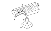
熱ローラ11aにシリコンオイル等の離型剤を供給する離型剤供給装置は、図1および図2に示す様に、離型剤を収容する離型剤タンク17と、離型剤タンク17内の離型剤を汲み上げるポンプ18と、タンク17から汲み上げられた離型剤を吐出する離型剤吐出部21aおよび該吐出部21aから吐出された離型剤20の液面を均一にする液面整え部21bを有する離型剤供給部材21からなり、離型剤供給部材21において均一な液面をなした離型剤部位に被塗布体となる離型剤塗布ローラ14が設けられている。
【0018】
本構成において、離型剤20は、ポンプ18によってタンク17内から汲み上げられ、離型剤供給部材21に設けられた離型剤吐出部21aから吐出し、離型剤供給部材21上面を流れ降りる。
【0019】
この時、離型剤20は、各離型剤吐出部21a下方に設けらた液面整え部21bを通過する。ここで、液面整え部21bは、離型剤の流路を確保するとともに、離型剤が流れ降りて行くに従い、離型剤を被塗布体の長手方向に分散させる機能を有する部材として構成される。
【0020】
本実施例においては、離型剤供給部材21上面に対し高低差をなすための溝部211を形成することにより液面整え部21bを得ている。液面整え部21bを通過した離型剤20は、液面整え部21bの溝部211に溜まるため図3に示す様に離型剤吐出部21aから離れた部位においても離型剤の液面が均一となり、流路が確保されながら均等に流れ降りる。
【0021】
離型剤塗布ローラ14は、離型剤供給部材21の液面整え部21bの直下、即ち、均一な液面をなした離型剤部位にて接しており、熱ローラ11aに対し従動回転する様に取り付けられている。
【0022】
また、溝部211の下部に図1および図2に示す様に分岐溝212を形成し、離型剤の移行(流れ降りる)方向へ進むにつれて分岐する形状にすると、熱ローラ11aの軸方向に対する離型剤の分散性が向上され、より均一に供給塗布することができる。
【0023】
なお、液面整え部21bの溝部の形状については、図示した形状に限定されるものではなく、例えば「X」字形の交差する溝を離型剤塗布ローラ14の軸方向に並べて設けた場合にも同等の作用効果が得られることを実験により確認した。また、上記説明においては、液面整え部21bを離型剤供給部材21の上面に溝として形成した場合を例示したが、図9に示す様に離型剤供給部材21の上面に仕切り部材22を設けて凹部を形成し、これによって液面整え部21bを得るようにしてもよい。
【0024】
なお、本実施例においては、被塗布体が離型剤塗布ローラである場合について説明したが、被塗布体は離型剤塗布ローラに限定されるものではない。即ち、例えば、図4に示す様に離型剤供給部材21と熱ローラ11aの間に離型剤塗布ローラが介在しない場合には、該熱ローラが被塗布体に相当するのである。
【0025】
また、必要に応じては熱ローラのみに限らず、加圧ローラに離型剤を供給してもよく、この場合は、加圧ローラが被塗布体に相当することは言うまでもない。
【0026】
【発明の効果】
以上述べた如く、本発明によれば、被塗布体に離型剤を均一に供給することが可能な離型剤供給部材および離型剤供給装置を得ることができる。また、被塗布体に離型剤を均一に供給し、印刷品質の安定した定着装置を得ることができる。
【図面の簡単な説明】
【図1】本発明の定着装置の一実施例を示す斜視図。
【図2】本発明の離型剤供給部材の一部断面斜視図。
【図3】図2のA部拡大断面図。
【図4】本発明の他の実施例を示す斜視図。
【図5】電子写真装置の全体構成図。
【図6】従来の定着装置を示す斜視図。
【図7】従来の離型剤供給部材の一部断面斜視図。
【図8】図7のB部拡大断面図。
【図9】本発明の他の実施例を示す断面図。
【符号の説明】
6…印刷用紙(記録材)、11a…熱ローラ、11b加圧ローラ、14…離型剤塗布ローラ、17…離型剤タンク、18…ポンプ、21…離型剤供給部材、21a…離型剤吐出部、21b…液面整え部。[0001]
TECHNICAL FIELD OF THE INVENTION
The present invention relates to a release agent supply member for supplying a release agent to an object to be coated, a release agent supply device, and a fixing device using the same.
[0002]
[Prior art]
In a fixing device in which a toner image formed on a recording material is heated and pressed by a heat roller and a pressure roller to fix the toner image on the recording material, a release agent is applied to the surface of the heat roller, and the heat roller and the toner image are fixed. In general, consideration has been given to improving the mutual releasability of the two.
[0003]
Various types of release agent supply devices for use in this type of fixing device have been proposed in the past. One type of the release agent supply device is a
[0004]
In this configuration, the
[0005]
[Problems to be solved by the invention]
Meanwhile, in the case of the above-described conventional configuration, when the
[0006]
If the fixing step is performed in a state where the applied amount of the release agent is not uniform, a gloss difference may occur in the toner image after fixing in a portion where the applied amount of the release agent is excessive. In addition, since a proper release property on the surface of the
[0007]
An object of the present invention is to provide a release agent supply member and a release agent supply device capable of uniformly supplying a release agent to an object to be coated.
[0008]
It is another object of the present invention to provide a fixing device that supplies a release agent uniformly to an object to be coated and has stable printing quality.
[0009]
[Means for Solving the Problems]
The above object is achieved by providing a release agent supply member with a release agent discharge section for discharging a release agent, and forming a flow path of the release agent discharged from the discharge section, and moving in a transfer direction of the release agent. This is achieved by forming a groove portion that branches off as a result, and a liquid level adjusting portion that makes the liquid level of the release agent supplied to the groove portion uniform.
[0010]
BEST MODE FOR CARRYING OUT THE INVENTION
Hereinafter, embodiments of the present invention will be described with reference to the drawings.
[0011]
In FIG. 5,
[0012]
The paper hopper 7 accommodates a continuous band-shaped recording material (printing paper) 6 for transferring and fixing the toner image and performing image printing in a folded state.
[0013]
The
[0014]
[0015]
The
[0016]
A pair of
[0017]
As shown in FIGS. 1 and 2, a release agent supply device for supplying a release agent such as silicone oil to the
[0018]
In this configuration, the
[0019]
At this time, the
[0020]
In the present embodiment, a liquid
[0021]
The release
[0022]
Also, a
[0023]
The shape of the groove of the
[0024]
In this embodiment, the case where the object to be coated is a release agent applying roller has been described, but the object to be applied is not limited to the release agent applying roller. That is, for example, when a release agent application roller is not interposed between the release
[0025]
If necessary, a release agent may be supplied not only to the heat roller but also to the pressure roller. In this case, it goes without saying that the pressure roller corresponds to the object to be coated.
[0026]
【The invention's effect】
As described above, according to the present invention, it is possible to obtain a release agent supply member and a release agent supply device capable of uniformly supplying a release agent to an object to be coated. Further, it is possible to uniformly supply the release agent to the object to be coated, and to obtain a fixing device with stable print quality.
[Brief description of the drawings]
FIG. 1 is a perspective view showing one embodiment of a fixing device of the present invention.
FIG. 2 is a partially sectional perspective view of a release agent supply member of the present invention.
FIG. 3 is an enlarged sectional view of a portion A in FIG. 2;
FIG. 4 is a perspective view showing another embodiment of the present invention.
FIG. 5 is an overall configuration diagram of the electrophotographic apparatus.
FIG. 6 is a perspective view showing a conventional fixing device.
FIG. 7 is a partial cross-sectional perspective view of a conventional release agent supply member.
8 is an enlarged sectional view of a portion B in FIG. 7;
FIG. 9 is a sectional view showing another embodiment of the present invention.
[Explanation of symbols]
6 printing paper (recording material), 11a heat roller, 11b pressure roller, 14 release agent application roller, 17 release agent tank, 18 pump, 21 release agent supply member, 21a release Agent discharge section, 21b ... liquid level adjusting section.
Claims (3)
前記離型剤供給部材は、前記離型剤タンクから汲み上げられた離型剤を吐出する離型剤吐出部と、該出部から吐出された離型剤の流路をなすとともに離型剤の移行方向へ進むにつれて分岐した溝部と、前記溝部に供給された離型剤の液面を均一にする液面整え部を有し、前記離型剤塗布ローラを、前記離型剤供給部材において均一な液面をなした離型剤部位に設けたことを特徴とする定着装置。A heat roller, a pressure roller provided so as to be able to press against the heat roller, a release agent application roller for contacting the surface of the heat roller and applying a release agent to the surface, and a release agent for accommodating the release agent. A release agent tank, a pump for pumping the release agent in the release agent tank, and a release agent supply member for supplying the release agent pumped from the release agent tank to the release agent application roller. A fixing device for fixing a toner image on the surface of the recording material at a pressure contact portion between the heat roller and the pressure roller;
The release agent supply member includes a release agent discharge unit that discharges the release agent pumped up from the release agent tank, and forms a flow path of the release agent discharged from the discharge unit and supplies the release agent. It has a groove portion that branches off as it moves in the transition direction, and a liquid level adjusting portion that makes the liquid level of the release agent supplied to the groove portion uniform, and the release agent application roller is made uniform in the release agent supply member. A fixing device, wherein the fixing device is provided at a part of the release agent having a proper liquid level.
Priority Applications (3)
| Application Number | Priority Date | Filing Date | Title |
|---|---|---|---|
| JP28373896A JP3555641B2 (en) | 1996-10-25 | 1996-10-25 | Release agent supply member, release agent supply device, and fixing device using the same |
| US08/955,116 US5881348A (en) | 1996-10-25 | 1997-10-21 | Release agent supplying member, release agent supplying apparatus and fixing apparatus using the same |
| DE19746880A DE19746880C2 (en) | 1996-10-25 | 1997-10-23 | Release or solvent supply element, release agent supply device and fixing device with such a device |
Applications Claiming Priority (1)
| Application Number | Priority Date | Filing Date | Title |
|---|---|---|---|
| JP28373896A JP3555641B2 (en) | 1996-10-25 | 1996-10-25 | Release agent supply member, release agent supply device, and fixing device using the same |
Publications (2)
| Publication Number | Publication Date |
|---|---|
| JPH10123872A JPH10123872A (en) | 1998-05-15 |
| JP3555641B2 true JP3555641B2 (en) | 2004-08-18 |
Family
ID=17669472
Family Applications (1)
| Application Number | Title | Priority Date | Filing Date |
|---|---|---|---|
| JP28373896A Expired - Lifetime JP3555641B2 (en) | 1996-10-25 | 1996-10-25 | Release agent supply member, release agent supply device, and fixing device using the same |
Country Status (3)
| Country | Link |
|---|---|
| US (1) | US5881348A (en) |
| JP (1) | JP3555641B2 (en) |
| DE (1) | DE19746880C2 (en) |
Families Citing this family (3)
| Publication number | Priority date | Publication date | Assignee | Title |
|---|---|---|---|---|
| US6032016A (en) * | 1997-09-19 | 2000-02-29 | Minolta Co., Ltd. | Fixing apparatus including apparatus for controlling the supply of releasing agent |
| JP4144850B2 (en) * | 2001-07-19 | 2008-09-03 | キヤノン株式会社 | Liquid applicator applicable to ink recorded medium and image forming apparatus having the same |
| US7409183B2 (en) * | 2003-12-08 | 2008-08-05 | Sharp Kabushiki Kaisha | Releasing agent applying mechanism, fixing device, and printing apparatus |
Family Cites Families (5)
| Publication number | Priority date | Publication date | Assignee | Title |
|---|---|---|---|---|
| DE2703382C3 (en) * | 1977-01-27 | 1979-07-19 | Siemens Ag, 1000 Berlin Und 8000 Muenchen | Device for supplying separating liquid to the surface of a fixing roller |
| JPH0268583A (en) * | 1988-09-02 | 1990-03-08 | Hitachi Koki Co Ltd | Laser printer |
| US5045889A (en) * | 1990-08-20 | 1991-09-03 | Eastman Kodak Company | Release liquid applying wick having a grooved feed tube |
| DE4212531C1 (en) * | 1992-04-15 | 1993-10-21 | Vaw Ver Aluminium Werke Ag | Gas and release agent supply and distribution system for a continuous casting device |
| JP3331785B2 (en) * | 1994-11-15 | 2002-10-07 | 富士ゼロックス株式会社 | Fixing device |
-
1996
- 1996-10-25 JP JP28373896A patent/JP3555641B2/en not_active Expired - Lifetime
-
1997
- 1997-10-21 US US08/955,116 patent/US5881348A/en not_active Expired - Lifetime
- 1997-10-23 DE DE19746880A patent/DE19746880C2/en not_active Expired - Lifetime
Also Published As
| Publication number | Publication date |
|---|---|
| DE19746880C2 (en) | 2002-07-11 |
| US5881348A (en) | 1999-03-09 |
| JPH10123872A (en) | 1998-05-15 |
| DE19746880A1 (en) | 1998-05-07 |
Similar Documents
| Publication | Publication Date | Title |
|---|---|---|
| US6745002B2 (en) | Liquid-development electrophotographic apparatus | |
| US5629761A (en) | Toner print system with heated intermediate transfer member | |
| EP3608723B1 (en) | Fog development for digital offset printing applications | |
| US5987301A (en) | Paper conditioning system | |
| JPH06500406A (en) | liquid developing device | |
| US5970300A (en) | Apparatus for applying scents to paper in a printer/copier | |
| US5937258A (en) | Paper conditioner with articulating back-up/transfer rollers | |
| JP3555641B2 (en) | Release agent supply member, release agent supply device, and fixing device using the same | |
| JPH11249475A (en) | Releasing agent control structure, heating and pressuring fixing unit, and releasing agent supply method | |
| US6415124B1 (en) | Wet-type developing unit capable of reducing pressing power given to squeeze roller and capable of controlling toner density of liquid developer adhered on development roller | |
| US6249667B1 (en) | Conditioner rolls end seals | |
| JP2002108107A (en) | Image forming method and image forming apparatus | |
| US7058341B2 (en) | Electrostatic transfer type liquid electrophotographic printer using a continuous photoreceptor web as a photoreceptor medium | |
| JP2001170532A (en) | Roll coating device | |
| US5659864A (en) | Dual image forming apparatus and method of using same | |
| JPH0926732A (en) | Both-side image forming device | |
| JP3243363B2 (en) | Release agent coating device and fixing device provided with the same | |
| JP3694681B2 (en) | Wet image forming device | |
| JP3502547B2 (en) | Fixing device for image forming device | |
| JPH1152776A (en) | Releasing agent supply device of fixing device | |
| JPH07121047A (en) | Fixing device | |
| US5172176A (en) | Simulated central inlet/outlet oil mini-sump | |
| KR200168973Y1 (en) | Cleaning apparatus for printer | |
| JPH06100878B2 (en) | A device for supplying a releasing liquid to the surface of a fixing roller of an electrophotographic printing device or a copying device. | |
| JP2748888B2 (en) | Electrophotographic recording device |
Legal Events
| Date | Code | Title | Description |
|---|---|---|---|
| TRDD | Decision of grant or rejection written | ||
| A01 | Written decision to grant a patent or to grant a registration (utility model) |
Free format text: JAPANESE INTERMEDIATE CODE: A01 Effective date: 20040421 |
|
| A61 | First payment of annual fees (during grant procedure) |
Free format text: JAPANESE INTERMEDIATE CODE: A61 Effective date: 20040504 |
|
| R150 | Certificate of patent or registration of utility model |
Free format text: JAPANESE INTERMEDIATE CODE: R150 |
|
| S533 | Written request for registration of change of name |
Free format text: JAPANESE INTERMEDIATE CODE: R313533 |
|
| R350 | Written notification of registration of transfer |
Free format text: JAPANESE INTERMEDIATE CODE: R350 |
|
| FPAY | Renewal fee payment (event date is renewal date of database) |
Free format text: PAYMENT UNTIL: 20090521 Year of fee payment: 5 |
|
| FPAY | Renewal fee payment (event date is renewal date of database) |
Free format text: PAYMENT UNTIL: 20090521 Year of fee payment: 5 |
|
| S111 | Request for change of ownership or part of ownership |
Free format text: JAPANESE INTERMEDIATE CODE: R313111 |
|
| FPAY | Renewal fee payment (event date is renewal date of database) |
Free format text: PAYMENT UNTIL: 20090521 Year of fee payment: 5 |
|
| R350 | Written notification of registration of transfer |
Free format text: JAPANESE INTERMEDIATE CODE: R350 |
|
| FPAY | Renewal fee payment (event date is renewal date of database) |
Free format text: PAYMENT UNTIL: 20100521 Year of fee payment: 6 |
|
| FPAY | Renewal fee payment (event date is renewal date of database) |
Free format text: PAYMENT UNTIL: 20110521 Year of fee payment: 7 |
|
| FPAY | Renewal fee payment (event date is renewal date of database) |
Free format text: PAYMENT UNTIL: 20120521 Year of fee payment: 8 |
|
| FPAY | Renewal fee payment (event date is renewal date of database) |
Free format text: PAYMENT UNTIL: 20120521 Year of fee payment: 8 |
|
| FPAY | Renewal fee payment (event date is renewal date of database) |
Free format text: PAYMENT UNTIL: 20130521 Year of fee payment: 9 |
|
| FPAY | Renewal fee payment (event date is renewal date of database) |
Free format text: PAYMENT UNTIL: 20130521 Year of fee payment: 9 |
|
| EXPY | Cancellation because of completion of term |