JP3554677B2 - Kitchen furniture cabinet - Google Patents
Kitchen furniture cabinet Download PDFInfo
- Publication number
- JP3554677B2 JP3554677B2 JP18556499A JP18556499A JP3554677B2 JP 3554677 B2 JP3554677 B2 JP 3554677B2 JP 18556499 A JP18556499 A JP 18556499A JP 18556499 A JP18556499 A JP 18556499A JP 3554677 B2 JP3554677 B2 JP 3554677B2
- Authority
- JP
- Japan
- Prior art keywords
- cabinet
- plate
- drawer
- storage space
- kitchen furniture
- Prior art date
- Legal status (The legal status is an assumption and is not a legal conclusion. Google has not performed a legal analysis and makes no representation as to the accuracy of the status listed.)
- Expired - Fee Related
Links
Images


Landscapes
- Combinations Of Kitchen Furniture (AREA)
Description
【0001】
【発明の属する技術分野】
本発明は、例えば所謂システムキッチンや流し台等の厨房家具用キャビネットに関し、特に食器洗浄乾燥機等の厨房機器の組み込み及び配管と一般収納を行なうためのキャビネット構造に関するものである。
【0002】
【従来の技術】
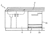
従来、所謂システムキッチンにおいては、例えば図8に示すように、システムキッチン1のベースキャビネット2に対して、食器洗浄乾燥機3を組み入れることが一般化している。
この場合、食器洗浄乾燥機3の組み込み位置が低いため、食器洗浄乾燥機3の扉3aを開いて、特に食器洗浄乾燥機3内の下段の網篭に対して食器の出し入れを行なう場合、使用者がかがむ等の無理な姿勢をとることになると共に、食器を移動する距離が比較的長くなってしまい、作業性が悪く使いづらかった。また場合によっては食器から垂れる水滴が厨房の床面に落ちてしまう等の問題があった。
【0003】
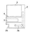
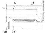
これに対して、図9乃至図11に示すように、食器洗浄乾燥機3のための棚板4を有する載置台をベースキャビネット2内に設けて、食器洗浄乾燥機3の組み込み高さを上げ、この棚板4の下方のスペースは引出し5のためのスペースとして利用し、更に床面付近の台輪2aのスペースで食器洗浄乾燥機3の給排水用の配管3bを連結する構成が採られていた。
【0004】
【発明が解決しようとする課題】
しかしながら、このような食器洗浄乾燥機3の配置では、食器洗浄乾燥機3の配管3bは台輪2a内に配管されるようになっているので、ベースキャビネット2の引出し5のためのスペースが小さくなってしまう。
さらに、引出し5のためのスペースは、配管連結やメンテナンスのための作業として利用するため、上記配管3bを、できるだけ台輪手前側の入口付近に配設する必要があり、配管が長くなり、コストが高くなるという問題があった。また、引出しのためのスペースである作業口が小さいため作業がしづらいという問題があった。
【0005】
本発明は、以上の点に鑑み、キャビネット下方に設けた引出しのスペースを大きく確保し、これによって配管連結の作業性を向上し、しかも食器洗浄乾燥機等の機器のための配管の長さをできるだけ短くするようにした、厨房家具用キャビネットを提供することを目的としている。また本発明は、機器の組み込みキャビネットでありながら、引出しのスペースを大きく確保することによって収納性を向上させることを目的としたものである。
【0006】
【課題を解決するための手段】
上記目的は、本発明によれば、左右の側板,背板及び底板とから成る上方及び前方が開放した箱体と、上側に厨房用機器のための第一の収納スペース及び下側に第二の収納スペースを画成するように、この箱体の中段に設けられていて、その後端縁が背板の手前に位置する中底板と、中底板の後端にて第二の収納スペースを、その後方の第一の収納スペースに連続した配管スペースに対して閉塞する区画板とを含んでおり、上記区画板が、開閉可能な点検口を備えている厨房家具用キャビネットにより、達成される。
【0007】
本発明による厨房家具用キャビネット内への厨房用機器としては、引き出し式の食器洗浄乾燥機が好ましい。
本発明による厨房家具用キャビネットは、好ましくは、上記区画板の前方の第二の収納スペース内に収納されていて、その第二の収納スペースほぼ全体が、前方に向かって引き出し可能な引出しによって構成されている。
【0008】
本発明による厨房家具用キャビネットは、好ましくは、上記中底板の前縁から下方に延びて、引出しの前板との間の間隙を閉鎖する化粧板を備えている。
【0009】
本発明による厨房家具用キャビネットは、好ましくは、上記化粧板が、厨房家具用キャビネットの前縁に対して着脱可能に、または揺動可能に取り付けられている。
【0010】
本発明による厨房家具用キャビネットは、好ましくは、上記引出しが、第二の収納スペース内に収容されると共に、その前板が、下端付近にて蹴込み部を備えている。
【0011】
上記構成によれば、配管スペースが、キャビネットの中底板の下方で且つ区画板の後方に画成されており、区画板に設けられた点検口から配管スペース内の配管の接続部のメンテナンスを行なうことができる。従って、区画板の前側に大きな収納スペースが確保され得ることになる。
また、配管スペースがキャビネットの後方に画成されていることから、配管の長さが比較的短くてすみ、無駄な配管の引回しが不要になると共に、本キャビネット内において、給水管,排水管及び電源コンセントの接続を行なうことができるので、接続作業が容易に行なわれ得る。
【0012】
好ましくは厨房用機器とし、引き出し式の食器洗浄乾燥機として構成されている。
上記区画板の前方の第二の収納スペース内に収容されていて、前方に向かって引き出し可能な引出しを備えている場合には、比較的大きな第二の収納スペースを引出しスペースとして使用することができるので、引出しが比較的大型に構成され得る。従って、この引出しにより、比較的大容量の収納容積が確保され得ることになる。
【0013】
上記中底板の前縁から下方に延びて、引出しの前板との間の間隙を閉鎖する化粧板を備えている場合には、任意の高さに設計されるキャビネット高さに対して、規格サイズの引出しを使用することにより、中底板の前縁と引出しの前板の上縁との間の間隙が、この化粧板によって閉じられ、見栄えが向上し、また厨房用機器のための第一の収納スペースの大小に応じて、化粧板の大きさを変えることで対応でき、引出しあるいは食器洗浄乾燥機の扉を造り変える必要がない。
【0014】
上記化粧板が、中底板の前縁に対して着脱可能に、または揺動可能に取り付けられている場合には、引出しを抜いた状態で、区画板の点検口から配管スペース内の配管の接続部のメンテナンスを行なう際に、第二の収納スペースの前面が完全に開放するので、メンテナンス作業が容易に行なわれ得ることになる。
【0015】
上記引出しが、第二の収納スペース内に収容されると共に、その前板が、下端付近にて蹴込み部を備えている場合には、従来のキャビネットにおいて台輪に設けられていた蹴込み部が引出しに備えられるので、使用者がシステムキッチンを使用する際に、その足先をこの蹴込み部内に入れることにより、よりキャビネットに接近して、楽に料理等の作業を行なうことができ、引出しを引き出した状態で、区画板の点検口から配管スペース内の配管の接続部のメンテナンスを行なう際に、第二の収納スペースの前面が完全に開放するので、メンテナンス作業が容易に行なわれ得ることになる。
【0016】
【発明の実施の形態】
以下、この発明の好適な実施の形態を図1乃至図7を参照しながら、詳細に説明する。
尚、以下に述べる実施の形態は、本発明の好適な具体例であるから、技術的に好ましい種々の限定が付されているが、本発明は、以下の説明において特に本発明を限定する旨の記載がない限り、これらの態様に限られるものではない。
【0017】
図1は、本発明による厨房家具用キャビネットの一実施の形態を組み込んだシステムキッチンの構成を示している。
図1において、システムキッチン10は、シンクS,加熱調理器Gを組み込んだ天板Tを備えた長尺の複合調理家具Fとして構成されている。
【0018】
この複合調理家具Fを構成するベースキャビネットKは、底板,左右の側板及び背板により上面及び前面が開放した複数個(図示の場合、4個)の各種キャビネットを構成する箱体をI型に配置し連結することにより構成されており、これらのベースキャビネットKの上面を一つの共通の天板Tで覆うと共に、各箱体の前面を覆う前板を備えた引出しを複数段配置している。
尚、各箱体の側板の前面側の下部は、所謂蹴込み部の高さ及び奥行きに合わせて切除されている。
【0019】
ここで、複数個のキャビネットは、図示の場合、左側から順に、それぞれコンロ用キャビネット14,引出しキャビネット15,シンク用キャビネット16,調理台用キャビネット20である。
コンロ用キャビネット14は、上面にコンロ(加熱調理器G)を備えると共に、三段の引出し14a,14b,14cを備えており、最上段の引出し14aは、コンロ14dを避けて、幅が狭く形成されている。
引出しキャビネット15は、三段の引出し15a,15b,15cを備えている。
シンク用キャビネット16は、公知の構成であって、上面にシンクSを備えると共に、二段の引出し16a,16bを備えており、上段の引出し16aの前板は、シンクSの前端を隠すための補助幕板を兼ねている。
【0020】
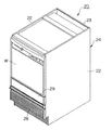
これに対して、上記調理台用キャビネット20は、本発明を適用して構成されたものであって、図2に示すように、上部には、ビルトイン機器としての食器洗浄乾燥機Wが組み込まれている。
尚、食器洗浄乾燥機Wは、調理台用キャビネット20から手前に引き出した状態(図6参照)にて、上から食器を出し入れすることができるように構成されており、シンクSで洗浄した食器を食器洗浄乾燥機W内に出し入れする際に、適宜の高さに配設されている。
【0021】
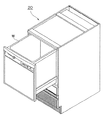
ここで、上記調理台用キャビネット20は、図3乃至図5に示すように、構成されている。
図3乃至図5において、調理台用キャビネット20は、底板21,左右の側板22及び背板23から成る箱体24と、この箱体の中段に設けられた中底板25と、配管スペースを画成する区画板26とを含んでいる。
【0022】
上記中底板25は、その後端縁が、背板23の手前に位置するように配設されており、その上方に食器洗浄乾燥機Wの専用(第一の)収納スペース25aと、その下方に後述する引出しのための第二の収納スペース25bとを画成すると共に、その後端縁と背板23との間に間隙dを形成している。
【0023】
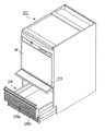
上記区画板26は、中底板25の後端から下方に延びることにより、その後方に配管スペース27を画成していると共に、開閉可能な点検口26aを備えている。
また、上記点検口26aは、図示の場合、蓋26bが着脱可能に螺着されることにより、通常は閉じられている。
【0024】
上記配管スペース27は、上記間隙dを介して、専用(第一の)収納スペース25aと連続するようになっていると共に、配管スペース27には、給水管27a及び排水管27b(図3参照)そして必要であれば電源コンセント(図示せず)が設けられており、それぞれ食器洗浄乾燥機Wの給水管W1,排水管W2及び電源コードW3が接続されるようになっている。
尚、図示の場合には、背板23の下部(中底板25より下方の部分)が切り欠かれており、厨房の壁面に設けられた電源コンセントを利用することも可能である。
【0025】
上記第二の収納スペース25bには、引出し28が前方に向かって引出し可能に収容されている。
引出し28は、図示の場合、所謂台輪の部分まで構成されており、その前板28aは、底板21に近い下部を凹状に形成することによって、所謂蹴込み部28bを備え、合成樹脂によって一体成形されている。これによって、第二の収納スペース25bほぼ全体を引出しとして構成している。
【0026】
ここで、引出し28は、規格品として構成されており、その前板28aの幅及び高さは一定である。
このため、引出し28の前板28aの上縁と中底板25の前縁との間の間隙を閉鎖するために、中底板25の前縁から下方に延びる化粧板29が設けられている。
この化粧板29は、上縁が、中底板25の前縁あるいはキャビネットに対して、着脱可能あるいは図7に示すように前方に向かって揺動可能に取り付けられている。
また、上方の第一の収納スペース25aに収納される食器洗浄乾燥機Wの作業性を良くすべく、食器洗浄乾燥機Wが小さい場合には、中底板25の位置を上方に取り付け、この化粧板29の大きさを大きいものと変えて使用することにより、規格品として構成された引出し28あるいは食器洗浄乾燥機を造り変えることなく使用できる。
【0027】
本発明の実施の形態によるシステムキッチン10は、以上のように構成されており、コンロ用キャビネット14,引出しキャビネット15,シンク用キャビネット16については、従来と同様に据付けられ使用される。
また、調理台用キャビネット20は、所定位置に配置された後に、引出し28を取り外すと共に、化粧板29が取り外され、または前に揺動した状態にて、さらに区画板26の蓋26bが取り外された状態で、専用(第一の)収納スペース25aに食器洗浄乾燥機Wが取り付けられる。その際、食器洗浄乾燥機Wの給水管W1,排水管W2及び電源コードW3が図3に示すように、配管スペース27内に露出している給水管27a,排水管27bそして図示しない電源コンセントに接続される。
このようにして、食器洗浄乾燥機Wの接続作業は、本調理台用キャビネット20内だけで行なわれることになり、容易に行なわれ得る。
その後、区画板26の蓋26bが点検口26aに取り付けられ、引出し28が第二の収納スペース25b内に装着されることにより、調理台用キャビネット20の据付けが完了する。
【0028】
このようにして据付けられた調理台用キャビネット20によれば、図6に示すように、食器洗浄乾燥機Wを引き出した状態にて、例えばシンクS内の食器が食器洗浄乾燥機W内に入れられ、また洗浄後の食器が食器洗浄乾燥機Wから取り出される。尚、食器洗浄及び乾燥は、食器洗浄乾燥機Wを図2に示すように収納した状態で行なわれる。
また、引出し28内への各種物品の出し入れは、図7に示すように、引出し28を引き出した状態で行なわれる。その際、化粧板29が手前に揺動されることにより、引出し28の内部への物品の出し入れが容易に行なわれ得る。
【0029】
さらに、配管スペース27における配管のメンテナンスを行なう場合には、先ず引出し28が取り外されると共に、化粧板29が取り外され、または手前に揺動され、さらに区画板26の蓋26bが取り外される。
この状態で、第二の収納スペース25bから点検口26aを介して、配管スペース27へのアクセスが行なわれ、配管のメンテナンス作業が行なわれる。この場合、第二の収納スペース25bは、所謂台輪に制限されることなく、また化粧板29が取り外され、または跳ね上げられた状態にあるので、点検口26aを介しての配管のメンテナンス作業が容易に行なわれ得る。
【0030】
尚、上述した実施の形態においては、専用(第一の)収納スペース25aには、引き出した状態上方が開放した所謂トップオープンタイプの食器洗浄乾燥機Wが収容されているが、これに限らず、他のタイプ、例えば扉タイプの食器洗浄乾燥機Wを収容してもよく、さらに食器洗浄乾燥機でなく他の食器乾燥庫,炊飯器等の電源を必要とする各種厨房機器を収容してもよい。
【0031】
【発明の効果】
以上述べたように、本発明による厨房家具用キャビネットによれば、配管スペースが、キャビネットの中底板の下方で且つ区画板の後方に画成されており、区画板に設けられた点検口から配管スペース内の配管の接続部のメンテナンスを行なうことができる。従って、区画板の前側に大きな収納スペースが確保され得ることになる。
また、配管スペースがキャビネットの後方に画成されていることから、配管の長さが比較的短くて済み、無駄な配管の引回しが不要になると共に、本キャビネット内において、給水管,排水管及び電源コンセントの接続を行なうことができるので、接続作業が容易に行なわれ得る。
そこで、食器洗浄乾燥機を組み入れる厨房家具用キャビネットに好適なものである。
【0032】
上記区画板の前方の第二の収納スペース内に収容されていて、前方に向かって引き出し可能な引出しを備えている場合には、比較的大きな第二の収納スペースを引出しスペースとして使用することができるので、引出しが比較的大型に構成され得る。従って、この引出しにより、比較的大容量の収納容積が確保され得ることになる。
【0033】
上記中底板の前縁から下方に延びて、引出しの前板との間の間隙を閉鎖する化粧板を備えている場合には、任意の高さに設計されるキャビネット高さに対して、規格サイズの引出しを使用することにより、中底板の前縁と引出しの前板の上縁との間の間隙が、この化粧板によって閉じられ、見栄えが向上し、また厨房用機器のための第一の収納スペースの大小に応じて、化粧板の大きさを変えることで対応でき、引出しを造り変える必要がない。
【0034】
上記化粧板が、中底板の前縁に対して着脱可能に、または揺動可能に取り付けられている場合には、引出しを引き出した状態で、区画板の点検口から配管スペース内の配管の接続部のメンテナンスを行なう際に、第二の収納スペースの前面が完全に開放するので、メンテナンス作業が容易に行なわれ得ることになる。
【0035】
上記引出しが、第二の収納スペース内に収容されると共に、その前板が、下端付近にて蹴込み部を備えている場合には、従来のキャビネットにおいて台輪に設けられていた蹴込み部が引出しに備えられるので、使用者がシステムキッチンを使用する際に、その足先をこの蹴込み部内に入れることにより、よりキャビネットに接近して、楽に料理等の作業を行なうことができ、引出しを引き出した状態で、区画板の点検口から配管スペース内の配管の接続部のメンテナンスを行なう際に、第二の収納スペースの前面が完全に開放するので、メンテナンス作業が容易に行なわれ得ることになる。
【0036】
かくして、本発明によれば、キャビネット下方に設けた引出しのスペースを大きく確保し、これによって配管連結の作業性を向上し、しかも食器洗浄乾燥機等の機器のための配管の長さをできるだけ短くするようにした、厨房家具用キャビネットが提供され得、また本発明は、機器の組み込みキャビネットでありながら、引出しのスペースを大きく確保することによって収納性を向上した厨房家具用キャビネットが提供され得る。
【図面の簡単な説明】
【図1】本発明による厨房家具用キャビネットの一実施の形態を組み込んだシステムキッチンの構成を示す斜視図である。
【図2】本発明による厨房家具用キャビネットの一実施の形態の構成を示す斜視図である。
【図3】図2の厨房家具用キャビネットの後方から見た概略斜視図である。
【図4】図3の厨房家具用キャビネットから食器洗浄乾燥機を外した状態を示す分解斜視図である。
【図5】図2の厨房家具用キャビネットの概略断面図である。
【図6】図2の厨房家具用キャビネットの食器洗浄乾燥機を引き出した状態を示す斜視図である。
【図7】図2の厨房家具用キャビネットの引出しを引き出した状態を示す斜視図である。
【図8】従来のシステムキッチンの一例の構成を示す概略正面図である。
【図9】従来のシステムキッチンにおける食器洗浄乾燥機用のキャビネットの構成例を示す概略断面図である。
【図10】図9のキャビネットにおける要部を示す正面図である。
【図11】図9のキャビネットにおける要部を示す断面図である。
【符号の説明】
10 システムキッチン
20 調理台用キャビネット(厨房家具用キャビネット)
21 底板
22 側板
23 背板
24 箱体
25 中底板
26 区画板
27 配管スペース
28 引出し
29 化粧板[0001]
TECHNICAL FIELD OF THE INVENTION
The present invention relates to a cabinet for kitchen furniture such as a so-called system kitchen or a sink, and more particularly to a cabinet structure for installing kitchen equipment such as a dishwasher and the like and performing piping and general storage.
[0002]
[Prior art]
Conventionally, in a so-called system kitchen, for example, as shown in FIG. 8, it is general to incorporate a
In this case, since the installation position of the dishwasher /
[0003]
On the other hand, as shown in FIGS. 9 to 11, a mounting table having a shelf plate 4 for the
[0004]
[Problems to be solved by the invention]
However, in such an arrangement of the dishwasher /
Further, since the space for the
[0005]
In view of the above, the present invention secures a large space for a drawer provided below the cabinet, thereby improving the workability of connecting pipes, and further reducing the length of pipes for equipment such as a dishwasher and the like. The aim is to provide a cabinet for kitchen furniture that is as short as possible. Another object of the present invention is to improve the storability by securing a large space for a drawer while being a built-in cabinet for a device.
[0006]
[Means for Solving the Problems]
According to the present invention, the above objects are achieved by a box having left and right side plates, a back plate, and a bottom plate which are open at the top and front, a first storage space for kitchen appliances on the upper side, and a second storage space on the lower side. In order to define the storage space of, the middle bottom plate is provided in the middle of this box body, the rear edge of which is located in front of the back plate, and the second storage space at the rear end of the middle bottom plate, A partition plate which is closed to a piping space continuous with the first storage space at the rear side, wherein the partition plate is achieved by a cabinet for kitchen furniture provided with a check opening which can be opened and closed.
[0007]
As kitchen equipment in the kitchen furniture cabinet according to the invention, a drawer-type dishwasher is preferred.
The cabinet for kitchen furniture according to the present invention is preferably stored in a second storage space in front of the partition plate, and substantially the entire second storage space is constituted by a drawer that can be drawn forward. Have been.
[0008]
The cabinet for kitchen furniture according to the invention preferably comprises a decorative panel extending downward from the front edge of the midsole and closing the gap between the drawer and the front panel.
[0009]
In the cabinet for kitchen furniture according to the present invention, preferably, the decorative board is detachably or swingably attached to the front edge of the cabinet for kitchen furniture.
[0010]
In the cabinet for kitchen furniture according to the present invention, preferably, the drawer is housed in the second storage space, and the front plate is provided with a riser near the lower end.
[0011]
According to the above configuration, the piping space is defined below the middle bottom plate of the cabinet and behind the partition plate, and performs maintenance of the connection portion of the piping in the piping space from the inspection port provided in the partition plate. be able to. Therefore, a large storage space can be secured on the front side of the partition plate.
Further, since the piping space is defined behind the cabinet, the length of the piping can be relatively short, and unnecessary piping of the piping is not required. In addition, since the power outlet can be connected, the connection operation can be easily performed.
[0012]
It is preferably a kitchen appliance and is configured as a drawer-type dishwasher.
If the drawer is housed in the second storage space in front of the partition plate and has a drawer that can be pulled out forward, a relatively large second storage space may be used as the drawer space. As such, the drawer can be configured to be relatively large. Therefore, a relatively large storage capacity can be secured by this drawing.
[0013]
If there is a decorative panel that extends downward from the front edge of the midsole plate and closes the gap between the drawer and the front plate, the standard for cabinet height designed to any height By using a drawer of size, the gap between the front edge of the midsole plate and the upper edge of the front plate of the drawer is closed by this decorative plate, improving the appearance and also the first for kitchen equipment. The size of the decorative board can be changed according to the size of the storage space, and there is no need to change the drawer or the dishwasher door.
[0014]
If the decorative panel is detachably or swingably attached to the front edge of the midsole panel, connect the piping in the piping space from the inspection port of the partition panel with the drawer removed. When the maintenance of the section is performed, the front face of the second storage space is completely opened, so that the maintenance work can be easily performed.
[0015]
In the case where the drawer is accommodated in the second storage space and the front plate is provided with a riser near the lower end, the riser provided in the base wheel in the conventional cabinet When the user uses the system kitchen, by putting his toes into this riser, the user can work closer to the cabinet and easily work on cooking, etc. When the pipe connection in the piping space is maintained from the inspection port of the partition plate in the state where it is pulled out, the front of the second storage space is completely open, so that maintenance work can be easily performed. become.
[0016]
BEST MODE FOR CARRYING OUT THE INVENTION
Hereinafter, a preferred embodiment of the present invention will be described in detail with reference to FIGS.
Note that the embodiments described below are preferred specific examples of the present invention, and therefore, various technically preferable limitations are added. However, the present invention is particularly limited in the following description. Are not limited to these embodiments unless otherwise described.
[0017]
FIG. 1 shows the configuration of a system kitchen incorporating a kitchen furniture cabinet according to an embodiment of the present invention.
In FIG. 1, a
[0018]
The base cabinet K constituting the composite cooking furniture F has an I-shaped box body constituting a plurality of (four in the illustrated case) various cabinets whose top and front surfaces are opened by a bottom plate, left and right side plates and a back plate. The base cabinet K is covered with a single common top plate T, and a plurality of drawers each having a front plate that covers the front surface of each box body are arranged. .
In addition, the lower part of the front side of the side plate of each box body is cut off according to the height and depth of a so-called riser.
[0019]
Here, the plurality of cabinets are a
The
The drawer cabinet 15 includes three
The
[0020]
On the other hand, the
The dishwasher / dryer W is configured so that the dishes can be taken in and out from above in a state of being pulled out from the countertop cabinet 20 (see FIG. 6). Is placed at an appropriate height when taking in and out of the dishwasher / dryer W.
[0021]
Here, the
3 to 5, a
[0022]
The
[0023]
The
In the case shown in the figure, the
[0024]
The piping
In the illustrated case, the lower portion of the back plate 23 (the portion below the midsole plate 25) is cut out, and a power outlet provided on the wall surface of the kitchen can be used.
[0025]
The
In the case of the drawing, the
[0026]
Here, the
Therefore, in order to close the gap between the upper edge of the
The
In order to improve the workability of the dishwasher / dryer W stored in the upper first storage space 25a, when the dishwasher / dryer W is small, the position of the
[0027]
The
Further, after the
In this manner, the connection operation of the dishwasher / dryer W is performed only in the
Thereafter, the
[0028]
According to the
In addition, as shown in FIG. 7, various articles are put in and out of the
[0029]
Further, when performing maintenance of the piping in the
In this state, access to the
[0030]
In the above-described embodiment, the so-called top-open type dishwasher / dryer W is housed in the dedicated (first) storage space 25a in which the upper part is opened in a pulled-out state, but is not limited to this. It may house another type, for example, a door-type dishwasher / dryer W, and further house not only the dishwasher / dryer but also other kitchen appliances requiring a power source such as a dishwasher, a rice cooker and the like. Is also good.
[0031]
【The invention's effect】
As described above, according to the kitchen furniture cabinet of the present invention, the piping space is defined below the middle bottom plate of the cabinet and behind the partition plate, and the piping space is defined by the inspection port provided in the partition plate. Maintenance of the connection of the piping in the space can be performed. Therefore, a large storage space can be secured on the front side of the partition plate.
Further, since the piping space is defined behind the cabinet, the length of the piping is relatively short, so that unnecessary piping is not required, and the water supply pipe and the drain pipe are provided inside the cabinet. In addition, since the power outlet can be connected, the connection operation can be easily performed.
Therefore, it is suitable for a cabinet for kitchen furniture incorporating a dishwasher.
[0032]
If the drawer is housed in the second storage space in front of the partition plate and has a drawer that can be pulled out forward, a relatively large second storage space may be used as the drawer space. As such, the drawer can be configured to be relatively large. Therefore, a relatively large storage capacity can be secured by this drawing.
[0033]
If there is a decorative panel that extends downward from the front edge of the midsole plate and closes the gap between the drawer and the front plate, the standard for cabinet height designed to any height By using a drawer of size, the gap between the front edge of the midsole plate and the upper edge of the front plate of the drawer is closed by this decorative plate, improving the appearance and also the first for kitchen equipment. It can be handled by changing the size of the decorative board according to the size of the storage space, and there is no need to change the drawer.
[0034]
When the decorative plate is detachably or swingably attached to the front edge of the midsole plate, connect the piping in the piping space from the inspection port of the partition plate with the drawer pulled out. When the maintenance of the section is performed, the front face of the second storage space is completely opened, so that the maintenance work can be easily performed.
[0035]
In the case where the drawer is accommodated in the second storage space and the front plate is provided with a riser near the lower end, the riser provided in the base wheel in the conventional cabinet When the user uses the system kitchen, by putting his toes into this riser, the user can work closer to the cabinet and easily work on cooking, etc. When the pipe connection in the piping space is maintained from the inspection port of the partition plate in the state where it is pulled out, the front of the second storage space is completely open, so that maintenance work can be easily performed. become.
[0036]
Thus, according to the present invention, a large space for the drawer provided below the cabinet is secured, thereby improving the workability of connecting the pipes, and further reducing the length of the pipes for equipment such as a dishwasher and the like as much as possible. Thus, a cabinet for kitchen furniture can be provided, and the present invention can provide a cabinet for kitchen furniture, which is a built-in cabinet for equipment and has improved storage efficiency by securing a large space for a drawer.
[Brief description of the drawings]
FIG. 1 is a perspective view showing the configuration of a system kitchen incorporating a kitchen furniture cabinet according to an embodiment of the present invention.
FIG. 2 is a perspective view showing a configuration of an embodiment of a cabinet for kitchen furniture according to the present invention.
FIG. 3 is a schematic perspective view of the kitchen furniture cabinet of FIG. 2 as viewed from the rear.
FIG. 4 is an exploded perspective view showing a state in which the dishwasher is removed from the kitchen furniture cabinet of FIG. 3;
FIG. 5 is a schematic sectional view of the cabinet for kitchen furniture of FIG. 2;
6 is a perspective view showing a state in which the dishwasher of the kitchen furniture cabinet of FIG. 2 is drawn out.
7 is a perspective view showing a state where the drawer of the cabinet for kitchen furniture of FIG. 2 is drawn out.
FIG. 8 is a schematic front view showing a configuration of an example of a conventional system kitchen.
FIG. 9 is a schematic sectional view showing a configuration example of a cabinet for a dishwasher in a conventional system kitchen.
FIG. 10 is a front view showing a main part of the cabinet of FIG. 9;
FIG. 11 is a sectional view showing a main part of the cabinet of FIG. 9;
[Explanation of symbols]
10
21
Claims (7)
上側に厨房用機器のための第一の収納スペース及び下側に第二の収納スペースを画成するように、この箱体の中段に設けられていて、その後端縁が背板の手前に位置する中底板と、
中底板の後端にて第二の収納スペースを、その後方の第一の収納スペースに連続した配管スペースに対して閉塞する区画板とを含んでおり、
上記区画板が、点検口を備えていることを特徴とする厨房家具用キャビネット。An upper and front open box comprising left and right side plates, a back plate and a bottom plate;
It is provided in the middle of this box so as to define a first storage space for kitchen appliances on the upper side and a second storage space on the lower side, and the rear edge is located in front of the back plate. The bottom plate
A partition plate closing the second storage space at the rear end of the midsole plate with respect to a piping space continuous with the first storage space behind the second storage space,
A cabinet for kitchen furniture, wherein the partition plate has an inspection opening.
Priority Applications (1)
| Application Number | Priority Date | Filing Date | Title |
|---|---|---|---|
| JP18556499A JP3554677B2 (en) | 1999-06-30 | 1999-06-30 | Kitchen furniture cabinet |
Applications Claiming Priority (1)
| Application Number | Priority Date | Filing Date | Title |
|---|---|---|---|
| JP18556499A JP3554677B2 (en) | 1999-06-30 | 1999-06-30 | Kitchen furniture cabinet |
Publications (2)
| Publication Number | Publication Date |
|---|---|
| JP2001008753A JP2001008753A (en) | 2001-01-16 |
| JP3554677B2 true JP3554677B2 (en) | 2004-08-18 |
Family
ID=16173027
Family Applications (1)
| Application Number | Title | Priority Date | Filing Date |
|---|---|---|---|
| JP18556499A Expired - Fee Related JP3554677B2 (en) | 1999-06-30 | 1999-06-30 | Kitchen furniture cabinet |
Country Status (1)
| Country | Link |
|---|---|
| JP (1) | JP3554677B2 (en) |
Cited By (1)
| Publication number | Priority date | Publication date | Assignee | Title |
|---|---|---|---|---|
| CN107000871A (en) * | 2014-10-24 | 2017-08-01 | 米恰特克公司 | For the vacuum drawer with exercisable lid for encapsulating food vacuum |
Families Citing this family (6)
| Publication number | Priority date | Publication date | Assignee | Title |
|---|---|---|---|---|
| JP4655380B2 (en) * | 2001-02-20 | 2011-03-23 | 株式会社ノーリツ | cabinet |
| JP3778450B2 (en) * | 2004-08-05 | 2006-05-24 | サンウエーブ工業株式会社 | System kitchen |
| JP2007075475A (en) * | 2005-09-16 | 2007-03-29 | Yamaha Livingtec Corp | Piping structure of cabinet for dishwasher |
| JP5118901B2 (en) * | 2007-06-28 | 2013-01-16 | クリナップ株式会社 | Kitchen furniture |
| JP6732211B2 (en) * | 2016-06-15 | 2020-07-29 | Toto株式会社 | Face-to-face system kitchen |
| CN108552792A (en) * | 2018-05-02 | 2018-09-21 | 佛山市顺德区美的洗涤电器制造有限公司 | kitchen appliance |
-
1999
- 1999-06-30 JP JP18556499A patent/JP3554677B2/en not_active Expired - Fee Related
Cited By (2)
| Publication number | Priority date | Publication date | Assignee | Title |
|---|---|---|---|---|
| CN107000871A (en) * | 2014-10-24 | 2017-08-01 | 米恰特克公司 | For the vacuum drawer with exercisable lid for encapsulating food vacuum |
| CN107000871B (en) * | 2014-10-24 | 2019-05-31 | 米恰特克公司 | Vacuum drawer with operable lid for vacuum encapsulating food |
Also Published As
| Publication number | Publication date |
|---|---|
| JP2001008753A (en) | 2001-01-16 |
Similar Documents
| Publication | Publication Date | Title |
|---|---|---|
| JPS6254002B2 (en) | ||
| JP3554677B2 (en) | Kitchen furniture cabinet | |
| JP4974784B2 (en) | System kitchen | |
| JP2512245B2 (en) | Island kitchen | |
| JPS6318484B2 (en) | ||
| JPH018196Y2 (en) | ||
| JP7376858B2 (en) | Cooking table with dining table and floor plan structure of apartment complex | |
| JP7603366B2 (en) | Indoor storage structure | |
| JP2000236964A (en) | Kitchen furniture cabinets | |
| JP4989131B2 (en) | Housing equipment | |
| CN211943098U (en) | Novel structure washing machine cabinet of pulling type motor home | |
| JPH0410306Y2 (en) | ||
| JP7547007B2 (en) | kitchen | |
| JPH04281925A (en) | Kitchen table | |
| JP2005152082A (en) | Piping cabinet for kitchen furniture | |
| JPH0576421A (en) | Island kitchen | |
| JP2003310517A (en) | Kitchen equipment | |
| KR950000274Y1 (en) | Tableware washing machine | |
| JP2000308534A (en) | Installing structure of kitchen cabinet | |
| JPH05146334A (en) | Subsync | |
| JPH0616729B2 (en) | Kitchen equipment | |
| JPH0197731A (en) | kitchen equipment | |
| JP2538681Y2 (en) | Kitchen equipment | |
| JP4993483B2 (en) | System kitchen | |
| JPS6255407B2 (en) |
Legal Events
| Date | Code | Title | Description |
|---|---|---|---|
| TRDD | Decision of grant or rejection written | ||
| A01 | Written decision to grant a patent or to grant a registration (utility model) |
Free format text: JAPANESE INTERMEDIATE CODE: A01 Effective date: 20040420 |
|
| A61 | First payment of annual fees (during grant procedure) |
Free format text: JAPANESE INTERMEDIATE CODE: A61 Effective date: 20040510 |
|
| R150 | Certificate of patent or registration of utility model |
Free format text: JAPANESE INTERMEDIATE CODE: R150 |
|
| R250 | Receipt of annual fees |
Free format text: JAPANESE INTERMEDIATE CODE: R250 |
|
| FPAY | Renewal fee payment (event date is renewal date of database) |
Free format text: PAYMENT UNTIL: 20100514 Year of fee payment: 6 |
|
| FPAY | Renewal fee payment (event date is renewal date of database) |
Free format text: PAYMENT UNTIL: 20100514 Year of fee payment: 6 |
|
| FPAY | Renewal fee payment (event date is renewal date of database) |
Free format text: PAYMENT UNTIL: 20110514 Year of fee payment: 7 |
|
| FPAY | Renewal fee payment (event date is renewal date of database) |
Free format text: PAYMENT UNTIL: 20120514 Year of fee payment: 8 |
|
| LAPS | Cancellation because of no payment of annual fees |