【0001】
【産業上の利用分野】
本発明はテレビジョン受像機などの映像機器や、自動車、各種音響機器に利用されるスピーカ前面に音波を導く音響管を結合したスピーカ装置に関するものである。
【0002】
【従来の技術】
スピーカの前面にホーンや音響管を結合し、スピーカから発生した音波を上記音響管の開口部まで導く方法は、ホーンや音響管を用いない場合に比べて出力音圧が大きく得られることや、特定の方向に音が伝えられるなどの利点があり、従来から多く用いられている。
【0003】
以下、図面を参照し従来の音響管を用いたスピーカ装置について説明する。
図9は、上記従来のスピーカ装置を内蔵したテレビジョン受像機の構造概念図であり、図9において1は音響管、2はスピーカ、18はテレビキャビネット、19は陰極線管、20はバックキャビネットを表したものである。
【0004】
以上のように構成されたスピーカ装置を内蔵したテレビジョン受像機の動作について説明する。図9に示すように、スピーカ2の前面部に音波を導く音響管1を結合したスピーカ装置をテレビジョン受像機内部の陰極線管19に沿わせて内蔵し、さらにテレビキャビネット18を上記スピーカ装置に沿わせる構造とすることにより、テレビジョン受像機の小型スリム化が可能となるものである。
【0005】
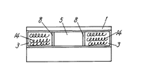
図7は上記従来のスピーカ装置の構成を示した構造概念図、図8はこの図7に示す従来のスピーカ装置の構成を音響管開口部方向より示した正面図である。
【0006】
図7において、6はスピーカ2の前面部に設けられた音響レンズ、8はスピーカ取付面7及び開口部5に対して垂直方向に配置した反射板、14は前記音響管1内部に配置した反射板8の両サイドに配置した吸音材、3は音響管1を構成する矩形形状の長辺方向の一方の面の反射板8の両サイドに配置された吸音材挿入孔、4は吸音材14を挿入した後密閉する構成とした密閉カバーである。
【0007】
以上のように構成された従来のスピーカ装置について以下にその動作を説明する。
【0008】
スピーカ2に入力信号が印加されると音波が音響管1の内部を通って音響管開口部5から放射されるものである。しかし、音響管開口部5で音響インピーダンスが大きく変化しているため音波の一部は反射して、内部に戻ってきて定在波を作り、また音響管1の長さで発生する定在波によりピークディップの激しい乱れた再生音圧周波数特性になってしまう。
【0009】
しかしながら、音響管1の内部に配置した吸音材14は、この各定材波を吸収し抑制することにより平坦な再生音圧周波数特性を作り出す。これによって細長くほぼ矩形形状に近い形状に構成された音響管開口部5により自然な音響再生が可能となるように構成されたものであった。
【0010】
【発明が解決しようとする課題】
しかしながら上記従来の構成では、図7に示すように音響管1の内部に発生する定在波を抑えるために吸音材14が設けてあるものの、図6の符号15に示すように中域再生帯域のピーク及びディップを取りきることができず、再生音圧周波数特性を低下させるという課題を有していた。
【0011】
また、定在波を抑えるためには吸音材14を大量に使用せざるを得ず、コスト面でも課題を残しているものであった。
【0012】
本発明は上記従来の課題を解決するもので、中域の再生音圧周波数特性の向上と低コスト化を図り、更に再生音圧周波数特性が平坦になる音響特性の優れたスピーカ装置を提供することを目的とするものである。
【0013】
【課題を解決するための手段】
この課題を解決するために本発明のスピーカ装置は、スピーカの前面に開口部が矩形形状の音波を導く音響管を結合し、この音響管の内部に、スピーカ取付面及び開口部に対して垂直方向に反射板を配置すると共に、この反射板と音響管の短径側側壁とスピーカ取付面に囲まれた空間部で音響管の長径側の側面を開放した吸音孔をそれぞれ形成し、この吸音孔の開放面部に開放面を密閉するように形成された吸音孔圧力制御カバーを結合した構成としたものである。
【0014】
【作用】
この構成により、機器への組み込みを考慮し開口部を細長い矩形形状としたホーンや音響管を有するスピーカ装置においても、スピーカ前面部の音響管内部を構成する反射板及び吸音孔を配置し、且つ、吸音孔を密閉するように形成された密閉カバーを吸音孔圧力制御カバーとすることで中域のピークディップを吸音孔内の圧力を変化させることにより抑制することができ、中域の再生周波数特性を向上させることができる。
【0015】
【実施例】
(実施例1)
以下、本発明の一実施例について図面を参照しながら説明する。
【0016】
図1は同実施例におけるスピーカ装置の構成を示した斜視図であり、図2(a)〜(c)はこの図1のA−A′断面、B−B′断面、C−C′断面をそれぞれ示したものであり、上記図7を用いて説明した従来のスピーカ装置と同じ構成の部品には同じ符号を付与し、詳細な説明は省略する。
【0017】
図1,図2において1は音響管であり、8はスピーカ取付面7及び開口部5に対して垂直方向に配置した反射板、9は音響管内部の反射板8の両サイドに設けられた吸音孔で、10はこの吸音孔9の上面を密閉するための吸音孔圧力制御カバーである。6はスピーカ2の前面の開口部に設けられた音響レンズである。ここで、吸音孔圧力制御カバー10の材質を弾性材、例えば、ゴム、シリコン、樹脂を含浸した紙などにすることにより吸音孔9の圧力を制御し、音響特性の補正をしようとするものである。
【0018】
以上のように構成された本発明のスピーカ装置について、以下にその動作を説明する。
【0019】
まず、スピーカ2に入力信号が印加されると、図2(c)の矢印に示すように、その音波が音響管1の内部を通って音響管開口部5から放射される。その際、音響管1の内部に発生する定在波を吸音孔9に取り入れ、吸音孔9を密閉している吸音孔圧力制御カバー10により上記定在波の空気の圧力を調整するように構成したものであり、このようにして中域の周波数帯域に発生する定在波による空気の圧力を調整することにより、中域の周波数特性を任意の音圧に調整することが可能となる。
【0020】
以上、本実施例によるスピーカ装置の再生音圧周波数特性を従来のスピーカ装置の同特性と比較して図6の符号16に示している。
【0021】
この図6からも分かるように吸音孔9を密閉している吸音孔圧力制御カバー10を設けた構成にすることにより、中域の周波数帯域に発生する定在波を制御すると同時に、再生音圧周波数特性にピークディップを少なくすることができ、中域の音圧を調整することが可能となる。
【0022】
また、図3に示すように上記吸音孔9を密閉するための吸音孔圧力制御カバー10Aを中央部硬質材部11、周辺弾性材部12により構成することによっても同様の効果を得ることができるものである。また、密閉カバーを有した構造をもつ音響管においても、再生音圧周波数特性の向上を図ることができる。
【0023】
また、本発明のスピーカ装置をテレビジョン受像機に内蔵することにより、テレビジョン受像機の小型スリム化を容易に実現できるほか、高性能で高音質のテレビジョン受像機とすることが可能となるものである。
【0024】
(実施例2)
以下、本発明の第2の実施例について図面を参照しながら説明する。
【0025】
図4は同実施例によるスピーカ装置の構成を示した斜視図であり、図4において1は音響管であり、9は音響管内部の反射板8の両サイドに設けられた吸音孔で、10Bは吸音孔9の上面を密閉するための吸音孔圧力制御カバーである。6はスピーカ2の前面の開口部に設けられた音響レンズである。ここで、吸音孔圧力制御カバー10Bを硬質材により構成し、前記吸音孔圧力制御カバー10Bの一部に孔13を設けるように構成することにより、吸音孔9の圧力を強制的に吸音孔9の外部に排出し、音響特性の補正をしようとするものであり、大きなピークディップの発生を抑制及び調整し、中域の再生音圧周波数特性を向上させることが可能となる。
【0026】
また、図4において、吸音孔圧力制御カバー10Bの材質を弾性材とすることにより、硬質材で構成された吸音孔圧力制御カバー10では調整できない微妙な中域の再生音圧周波数特性の調整が可能となる。
【0027】
以上、本実施例によるスピーカ装置の再生音圧周波数特性を従来のスピーカ装置の同特性と比較して図6の符号17に示している。
【0028】
(実施例3)
以下、本発明の第3の実施例について図面を参照しながら説明する。
【0029】
図5は同実施例によるスピーカ装置の構成を示した斜視図であり、図5において、1は音響管であり、9は音響管内部の反射板8の両サイドに設けられた吸音孔で、10Cは吸音孔9の上面を密閉するための吸音孔圧力制御カバーである。6はスピーカ2の前面の開口部に設けられた音響レンズである。ここで、吸音孔圧力制御カバー10Cを上記実施例1のように弾性材により構成したり、あるいは吸音孔圧力制御カバー10Cを上記実施例1の図3のように硬質材及び弾性材により構成したり、あるいは吸音孔圧力制御カバー10Cの一部に孔13を設けた構成とし、さらに吸音孔9に吸音材14を挿入することにより定在波の空気の圧力を吸音孔圧力制御カバー10Cにより調整すると共に吸音材14による抵抗負荷により圧力を調整することが可能となり、中域の再生音圧周波数特性の向上及び調整をより容易にすることが可能となり、吸音材14を設けていないときよりもピークディップを抑えることができ、音響特性をさらに平坦にすることができる。
【0030】
以上、本実施例によるスピーカ装置の再生音圧周波数特性を従来のスピーカ装置の同特性と比較して図6の符号21に示している。
【0031】
また、このスピーカ装置をテレビジョン受像機に組み込んだ場合の再生音圧周波数特性として見た場合、ピークディップの少ない特性とすることが可能となり、従来品では実現できなかった中音域の音圧のバランスの向上と再生音圧周波数特性の平坦化、さらに、吸音材14の少量化が図れ、優れた音響特性を実現できるものである。
【0032】
なお、本発明の音響管1の構造により構成されたスピーカ装置に、後面キャビネットおよびバスレフポート等を設けた場合においても同様の効果が得られることは言うまでもない。
【0033】
【発明の効果】
以上のように本発明によるスピーカ装置は、人間の声を形成する重要な中域の周波数帯域において、音圧のコントロールをすることができ、従来品では実現できなかった中域のバランスの向上を図った優れた音響特性を実現でき、また、吸音孔制御カバーの材質、形状により、定在波の圧力を制御することにより、音響管の内部に配置する吸音材の量を軽減することができ、コスト面でも優位なスピーカ装置を実現できるものである。
【図面の簡単な説明】
【図1】本発明の第1の実施例によるスピーカ装置の構造を示した分解斜視図
【図2】(a)図1のA−A′断面を示した断面図
(b)同B−B′断面を示した断面図
(c)同C−C′断面を示した断面図
【図3】同実施例の吸音孔圧力制御カバーの他の構成を示した斜視図
【図4】本発明の第2の実施例によるスピーカ装置の構造を示した分解斜視図
【図5】本発明の第3の実施例によるスピーカ装置の構造を示した分解斜視図
【図6】本発明のスピーカ装置の再生音圧周波数特性と従来のスピーカ装置の同特性を比較した特性図
【図7】従来のスピーカ装置の構成を示した分解斜視図
【図8】従来のスピーカ装置の構成を示した正面図
【図9】従来の音響管を用いたスピーカ装置を内蔵したテレビジョン受像機の構造概念図
【符号の説明】
1 音響管
2 スピーカ
5 音響管開口部
6 音響レンズ
7 スピーカ取付面
8 反射板
9 吸音孔
10,10A,10B,10C 吸音孔圧力制御カバー
11 中央硬質材部
12 周辺弾性材部
13 孔
14 吸音材
16 本発明の実施例1によるスピーカ装置の再生音圧周波数特性
17 本発明の実施例2によるスピーカ装置の再生音圧周波数特性
18 本発明の実施例3によるスピーカ装置の再生音圧周波数特性[0001]
[Industrial applications]
The present invention relates to a speaker device in which an acoustic tube for guiding sound waves is coupled to a front surface of a speaker used for a video device such as a television receiver, an automobile, and various audio devices.
[0002]
[Prior art]
A method in which a horn or an acoustic tube is coupled to the front of the speaker and the sound wave generated from the speaker is guided to the opening of the acoustic tube is that a large output sound pressure can be obtained as compared with a case where the horn or the acoustic tube is not used. It has the advantage that sound is transmitted in a specific direction, and has been widely used.
[0003]
Hereinafter, a conventional speaker device using an acoustic tube will be described with reference to the drawings.
FIG. 9 is a conceptual view of the structure of a television receiver incorporating the above-mentioned conventional speaker device. In FIG. 9, 1 is an acoustic tube, 2 is a speaker, 18 is a television cabinet, 19 is a cathode ray tube, and 20 is a back cabinet. It is a representation.
[0004]
The operation of the television receiver including the speaker device configured as described above will be described. As shown in FIG. 9, a speaker device in which an acoustic tube 1 for guiding sound waves is coupled to a front portion of a speaker 2 is built in along a cathode ray tube 19 inside a television receiver, and a television cabinet 18 is further provided in the speaker device. By adopting the structure along the direction, it is possible to reduce the size and size of the television receiver.
[0005]
FIG. 7 is a conceptual diagram showing the structure of the conventional speaker device, and FIG. 8 is a front view showing the structure of the conventional speaker device shown in FIG.
[0006]
7, reference numeral 6 denotes an acoustic lens provided on the front surface of the speaker 2, reference numeral 8 denotes a reflector disposed perpendicular to the speaker mounting surface 7 and the opening 5, and reference numeral 14 denotes a reflection disposed inside the acoustic tube 1. The sound absorbing material disposed on both sides of the plate 8, the sound absorbing material insertion holes 3 disposed on both sides of the reflecting plate 8 on one surface in the long side direction of the rectangular shape constituting the acoustic tube 1, and the sound absorbing material 14. This is a sealing cover that is configured to be sealed after insertion.
[0007]
The operation of the conventional speaker device configured as described above will be described below.
[0008]
When an input signal is applied to the speaker 2, a sound wave passes through the inside of the acoustic tube 1 and is radiated from the acoustic tube opening 5. However, since the acoustic impedance is greatly changed at the acoustic tube opening 5, a part of the sound wave is reflected, returns to the inside to form a standing wave, and a standing wave generated by the length of the acoustic tube 1. This results in a reproduced sound pressure frequency characteristic in which the peak dip is severely disturbed.
[0009]
However, the sound absorbing material 14 disposed inside the acoustic tube 1 creates a flat reproduced sound pressure frequency characteristic by absorbing and suppressing each constant wave. Thus, the acoustic tube opening 5 which is elongated and has a substantially rectangular shape is configured to enable natural sound reproduction.
[0010]
[Problems to be solved by the invention]
However, in the above-mentioned conventional configuration, although the sound absorbing material 14 is provided to suppress the standing wave generated inside the acoustic tube 1 as shown in FIG. 7, the middle band reproduction band as shown by reference numeral 15 in FIG. However, there was a problem that the reproduction sound pressure frequency characteristics could not be reduced because the peak and dip could not be removed.
[0011]
Further, in order to suppress the standing wave, a large amount of the sound absorbing material 14 has to be used, and a problem remains in terms of cost.
[0012]
SUMMARY OF THE INVENTION The present invention solves the above-mentioned conventional problems, and provides a speaker device having improved acoustic characteristics in which the reproduced sound pressure frequency characteristics are improved and the reproduced sound pressure frequency characteristics are flattened. It is intended for that purpose.
[0013]
[Means for Solving the Problems]
In order to solve this problem, a speaker device according to the present invention has an acoustic tube in which an opening guides a sound wave having a rectangular shape is coupled to a front surface of a speaker, and inside the acoustic tube, the acoustic tube is perpendicular to a speaker mounting surface and an opening. A sound absorbing hole is formed by opening the side of the long side of the acoustic tube in a space surrounded by the reflector, the short side wall of the acoustic tube, and the speaker mounting surface, respectively. The sound absorbing hole pressure control cover formed so as to seal the open surface is connected to the open surface of the hole.
[0014]
[Action]
With this configuration, even in a speaker device having a horn or a sound tube having an elongated rectangular shape in consideration of incorporation into a device, a reflection plate and a sound absorption hole constituting the inside of the sound tube on the front surface of the speaker are arranged, and By using a sound-absorbing-hole pressure control cover that is formed to seal the sound-absorbing hole, the mid-range peak dip can be suppressed by changing the pressure in the sound-absorbing hole. Characteristics can be improved.
[0015]
【Example】
(Example 1)
Hereinafter, an embodiment of the present invention will be described with reference to the drawings.
[0016]
FIG. 1 is a perspective view showing the configuration of the speaker device according to the embodiment. FIGS. 2A to 2C are cross-sectional views taken along lines AA ′, BB ′, and CC ′ of FIG. The same reference numerals are given to components having the same configuration as the conventional speaker device described with reference to FIG. 7, and a detailed description thereof will be omitted.
[0017]
1 and 2, reference numeral 1 denotes an acoustic tube, 8 is a reflector disposed perpendicular to the speaker mounting surface 7 and the opening 5, and 9 is provided on both sides of the reflector 8 inside the acoustic tube. A sound absorbing hole 10 is a sound absorbing hole pressure control cover for sealing the upper surface of the sound absorbing hole 9. Reference numeral 6 denotes an acoustic lens provided in an opening on the front surface of the speaker 2. Here, the sound absorbing hole pressure control cover 10 is made of an elastic material, for example, paper impregnated with rubber, silicon, or resin, to control the pressure of the sound absorbing hole 9 and to correct the acoustic characteristics. is there.
[0018]
The operation of the speaker device of the present invention configured as described above will be described below.
[0019]
First, when an input signal is applied to the speaker 2, the sound wave passes through the inside of the acoustic tube 1 and is radiated from the acoustic tube opening 5 as shown by an arrow in FIG. At this time, the standing wave generated inside the acoustic tube 1 is introduced into the sound absorbing hole 9, and the pressure of the air of the standing wave is adjusted by the sound absorbing hole pressure control cover 10 that seals the sound absorbing hole 9. By adjusting the pressure of the air by the standing wave generated in the middle frequency band in this way, it is possible to adjust the middle frequency characteristic to an arbitrary sound pressure.
[0020]
As described above, the reproduction sound pressure frequency characteristic of the speaker device according to the present embodiment is compared with the same characteristic of the conventional speaker device and is indicated by reference numeral 16 in FIG.
[0021]
As can be seen from FIG. 6, the provision of the sound-absorbing-hole pressure control cover 10 that seals the sound-absorbing hole 9 allows the standing wave generated in the middle frequency band to be controlled and the reproduced sound pressure to be controlled. The peak dip can be reduced in the frequency characteristics, and the sound pressure in the middle range can be adjusted.
[0022]
A similar effect can also be obtained by forming the sound absorbing hole pressure control cover 10A for sealing the sound absorbing hole 9 with the central hard material portion 11 and the peripheral elastic material portion 12 as shown in FIG. Things. Further, even in an acoustic tube having a structure having a closed cover, it is possible to improve the reproduction sound pressure frequency characteristics.
[0023]
In addition, by incorporating the speaker device of the present invention into a television receiver, it is possible to easily realize a small and slim television receiver, and to provide a high-performance and high-quality television receiver. Things.
[0024]
(Example 2)
Hereinafter, a second embodiment of the present invention will be described with reference to the drawings.
[0025]
FIG. 4 is a perspective view showing the configuration of the speaker device according to the embodiment. In FIG. 4, reference numeral 1 denotes an acoustic tube, and 9 denotes sound absorbing holes provided on both sides of a reflector 8 inside the acoustic tube. Reference numeral denotes a sound absorbing hole pressure control cover for sealing the upper surface of the sound absorbing hole 9. Reference numeral 6 denotes an acoustic lens provided in an opening on the front surface of the speaker 2. Here, the sound absorbing hole pressure control cover 10B is made of a hard material, and the hole 13 is provided in a part of the sound absorbing hole pressure control cover 10B. In order to correct the acoustic characteristic, suppress and adjust the occurrence of a large peak dip, and improve the reproduced sound pressure frequency characteristic in the middle range.
[0026]
Further, in FIG. 4, by making the material of the sound absorbing hole pressure control cover 10B an elastic material, it is possible to finely adjust the reproduction sound pressure frequency characteristics in the midrange which cannot be adjusted by the sound absorbing hole pressure control cover 10 made of a hard material. It becomes possible.
[0027]
As described above, the reproduction sound pressure frequency characteristic of the speaker device according to the present embodiment is compared with the same characteristic of the conventional speaker device and is indicated by reference numeral 17 in FIG.
[0028]
(Example 3)
Hereinafter, a third embodiment of the present invention will be described with reference to the drawings.
[0029]
FIG. 5 is a perspective view showing a configuration of the speaker device according to the embodiment. In FIG. 5, reference numeral 1 denotes an acoustic tube, and 9 denotes sound absorbing holes provided on both sides of a reflection plate 8 inside the acoustic tube. 10C is a sound absorbing hole pressure control cover for sealing the upper surface of the sound absorbing hole 9. Reference numeral 6 denotes an acoustic lens provided in an opening on the front surface of the speaker 2. Here, the sound absorbing hole pressure control cover 10C is made of an elastic material as in the first embodiment, or the sound absorbing hole pressure control cover 10C is made of a hard material and an elastic material as shown in FIG. 3 of the first embodiment. The pressure of the standing wave air is adjusted by the sound absorbing hole pressure control cover 10C by inserting the sound absorbing material 14 into the sound absorbing hole 9 or the sound absorbing hole pressure control cover 10C. In addition, the pressure can be adjusted by the resistance load of the sound absorbing material 14, and the improvement and adjustment of the reproduction sound pressure frequency characteristics in the middle range can be more easily performed, as compared with the case where the sound absorbing material 14 is not provided. The peak dip can be suppressed, and the acoustic characteristics can be further flattened.
[0030]
As described above, the reproduction sound pressure frequency characteristic of the speaker device according to the present embodiment is shown by reference numeral 21 in FIG.
[0031]
Also, when this speaker device is viewed as a reproduction sound pressure frequency characteristic when incorporated into a television receiver, it is possible to obtain a characteristic with a small peak dip, and the sound pressure of the middle sound range which cannot be realized with the conventional product. The balance can be improved, the reproduced sound pressure frequency characteristics can be flattened, and the amount of the sound absorbing material 14 can be reduced, so that excellent acoustic characteristics can be realized.
[0032]
It is needless to say that the same effect can be obtained even when a rear cabinet, a bass reflex port, and the like are provided in the speaker device having the structure of the acoustic tube 1 of the present invention.
[0033]
【The invention's effect】
As described above, the speaker device according to the present invention can control the sound pressure in the important middle frequency band that forms a human voice, and can improve the balance of the middle band which cannot be realized by the conventional product. The achieved excellent acoustic characteristics can be realized, and the amount of sound absorbing material placed inside the acoustic tube can be reduced by controlling the pressure of the standing wave by the material and shape of the sound absorbing hole control cover. Thus, a speaker device that is superior in cost can be realized.
[Brief description of the drawings]
FIG. 1 is an exploded perspective view showing a structure of a speaker device according to a first embodiment of the present invention. FIG. 2 (a) is a cross-sectional view showing an AA ′ cross section of FIG. FIG. 3 is a perspective view showing another configuration of the sound absorbing hole pressure control cover of the embodiment. FIG. 4 is a perspective view showing another configuration of the sound absorbing hole pressure control cover of the embodiment. FIG. 5 is an exploded perspective view showing the structure of the speaker device according to the second embodiment. FIG. 5 is an exploded perspective view showing the structure of the speaker device according to the third embodiment of the present invention. FIG. 7 is a characteristic diagram comparing sound pressure frequency characteristics and the same characteristics of a conventional speaker device. FIG. 7 is an exploded perspective view showing a configuration of a conventional speaker device. FIG. 8 is a front view showing a configuration of a conventional speaker device. 9: Structural conceptual diagram of a television receiver having a built-in speaker device using a conventional acoustic tube.
DESCRIPTION OF SYMBOLS 1 Acoustic tube 2 Speaker 5 Acoustic tube opening 6 Acoustic lens 7 Speaker mounting surface 8 Reflector 9 Sound absorbing holes 10, 10A, 10B, 10C Sound absorbing hole pressure control cover 11 Central hard material portion 12 Peripheral elastic material portion 13 Hole 14 Sound absorbing material 16 Reproduction sound pressure frequency characteristic of the speaker device according to the first embodiment of the invention 17 Reproduction sound pressure frequency characteristic of the speaker device according to the second embodiment of the invention 18 Reproduction sound pressure frequency characteristic of the speaker device according to the third embodiment of the invention