JP3550737B2 - Communication device - Google Patents
Communication device Download PDFInfo
- Publication number
- JP3550737B2 JP3550737B2 JP17979394A JP17979394A JP3550737B2 JP 3550737 B2 JP3550737 B2 JP 3550737B2 JP 17979394 A JP17979394 A JP 17979394A JP 17979394 A JP17979394 A JP 17979394A JP 3550737 B2 JP3550737 B2 JP 3550737B2
- Authority
- JP
- Japan
- Prior art keywords
- signal
- dtmf
- transmitting
- transmission
- dialing
- Prior art date
- Legal status (The legal status is an assumption and is not a legal conclusion. Google has not performed a legal analysis and makes no representation as to the accuracy of the status listed.)
- Expired - Fee Related
Links
- 238000004891 communication Methods 0.000 title claims description 28
- 230000008054 signal transmission Effects 0.000 claims description 19
- 230000005540 biological transmission Effects 0.000 claims description 15
- 239000000725 suspension Substances 0.000 claims 1
- 238000000034 method Methods 0.000 description 26
- 230000008569 process Effects 0.000 description 16
- 238000010586 diagram Methods 0.000 description 7
- 230000006870 function Effects 0.000 description 5
- 238000012545 processing Methods 0.000 description 5
- 230000004044 response Effects 0.000 description 4
- 101150040617 RTC4 gene Proteins 0.000 description 1
- 230000009471 action Effects 0.000 description 1
- 230000002238 attenuated effect Effects 0.000 description 1
- 230000006866 deterioration Effects 0.000 description 1
- 230000009977 dual effect Effects 0.000 description 1
- 230000000694 effects Effects 0.000 description 1
- 239000004973 liquid crystal related substance Substances 0.000 description 1
- 238000012986 modification Methods 0.000 description 1
- 230000004048 modification Effects 0.000 description 1
- 238000012544 monitoring process Methods 0.000 description 1
Images
Classifications
-
- H—ELECTRICITY
- H04—ELECTRIC COMMUNICATION TECHNIQUE
- H04M—TELEPHONIC COMMUNICATION
- H04M1/00—Substation equipment, e.g. for use by subscribers
- H04M1/26—Devices for calling a subscriber
- H04M1/27—Devices whereby a plurality of signals may be stored simultaneously
-
- H—ELECTRICITY
- H04—ELECTRIC COMMUNICATION TECHNIQUE
- H04M—TELEPHONIC COMMUNICATION
- H04M1/00—Substation equipment, e.g. for use by subscribers
- H04M1/26—Devices for calling a subscriber
- H04M1/27—Devices whereby a plurality of signals may be stored simultaneously
- H04M1/274—Devices whereby a plurality of signals may be stored simultaneously with provision for storing more than one subscriber number at a time, e.g. using toothed disc
- H04M1/2745—Devices whereby a plurality of signals may be stored simultaneously with provision for storing more than one subscriber number at a time, e.g. using toothed disc using static electronic memories, e.g. chips
- H04M1/27485—Appending a prefix to or inserting a pause into a dialling sequence
-
- H—ELECTRICITY
- H04—ELECTRIC COMMUNICATION TECHNIQUE
- H04M—TELEPHONIC COMMUNICATION
- H04M1/00—Substation equipment, e.g. for use by subscribers
- H04M1/26—Devices for calling a subscriber
- H04M1/30—Devices which can set up and transmit only one digit at a time
- H04M1/50—Devices which can set up and transmit only one digit at a time by generating or selecting currents of predetermined frequencies or combinations of frequencies
-
- H—ELECTRICITY
- H04—ELECTRIC COMMUNICATION TECHNIQUE
- H04Q—SELECTING
- H04Q1/00—Details of selecting apparatus or arrangements
- H04Q1/18—Electrical details
- H04Q1/30—Signalling arrangements; Manipulation of signalling currents
- H04Q1/44—Signalling arrangements; Manipulation of signalling currents using alternate current
- H04Q1/444—Signalling arrangements; Manipulation of signalling currents using alternate current with voice-band signalling frequencies
- H04Q1/45—Signalling arrangements; Manipulation of signalling currents using alternate current with voice-band signalling frequencies using multi-frequency signalling
- H04Q1/453—Signalling arrangements; Manipulation of signalling currents using alternate current with voice-band signalling frequencies using multi-frequency signalling in which m-out-of-n signalling frequencies are transmitted
Landscapes
- Engineering & Computer Science (AREA)
- Signal Processing (AREA)
- Computer Networks & Wireless Communication (AREA)
- Telephonic Communication Services (AREA)
- Facsimile Transmission Control (AREA)
- Telephone Function (AREA)
Description
【0001】
【産業上の利用分野】
本発明は通信網に接続された通信装置に関し、特に多重周波信号を送信する機能を備えた通信装置における信号制御方式に関するものである。
【0002】
【従来の技術】
近年、DTMF(デュアルトーンマルティプルフレケンシー:多重周波)信号、即ちいわゆるPB信号を使用した多くの装置が提案されている。例えばファクシミリ装置では、相手装置と接続された後に、DTMF信号を使用して相手装置を制御し、親展ポーリングや親展送信、中継同報などを指示可能である(特開昭63−104572号公報、特開昭63−300669号公報、特開平2−50560号公報、特開平3−260875号公報等参照)。これらのほとんどはオペレータによる手動送出であるが、自動的にDTMF信号を送出する技術も提案されている(特開平4−168862号公報)。
【0003】
【発明が解決しようとする課題】
上記のような従来のファクシミリ装置においては、電話網(交換機)に対するダイヤル時と、相手装置に対するDTMF信号の送信時において、信号送出時間、信号休止時間、信号送出レベル等のパラメータとして、同じ仕様のパラメータを用いて信号を送出していた。例えば日本の電話網に対する一般的な信号送出時間およびミニマムポーズ(信号休止時間)がそれぞれ60ミリ秒であったとすれば、この規格を満たすように信号を送出すれば、ダイヤル信号は正しく受信されるであろう。しかし接続された相手装置のDTMF信号受信能力(仕様)によってはDTMF信号を正しく検出できない可能性がある。このことは、相手装置が海外に存在する(海外の仕様に従って設計、製造された相手装置)場合には顕著である。例えばドイツでは信号の送出時間および信号休止時間をそれぞれ80〜100ミリ秒と規定している。従って、ドイツ仕様のファクシミリ装置においては、前記したような、信号送出時間および信号休止時間がそれぞれ60ミリ秒である信号は検出されず、DTMFによる制御が不可能であるという問題点があった。
【0004】
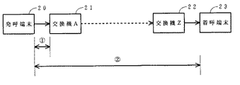
また送出したDTMF信号が減衰や劣化、雑音により相手装置まで正しく伝送されない場合もある。図2は通信網の一例を示すブロック図である。ダイヤル信号は発呼端末20から加入者回線を介して、該端末が収容されている交換機A21に伝送され、受信される(区間1)。しかし、着呼端末を制御するためのDTMF信号は、交換機A21から網内を通過して交換機Z22に伝送され、更に着呼端末23に伝送される。また着呼端末23から発呼端末20へ応答信号等を伝送する場合も同様である(区間2)。従って、制御用のDTMF信号はダイヤル信号に較べて、より大きな減衰や劣化を受けることになり、着呼端末23側において正常に受信できない場合があるというという問題点もあった。
本発明の目的は、前記のような従来技術の問題点を解決し、DTMF信号を確実に伝送可能な通信装置を提供することにある。
【0005】
【課題を解決するための手段】
第1の発明は、通信装置において、コード情報を入力する手段と、入力されたコードに基づき多重周波信号を送出する送信手段と、通信網に対するダイヤル時と通信網に対するダイヤル以外の時とで、多重周波信号の信号送出時間および信号休止時間の内の少なくとも一方を異なる値とする送信制御手段を備えたことを特徴とする。また、第2の発明は、通信装置において、コード情報を入力する手段と、入力されたコードに基づき多重周波信号を送出する送信手段と、通信網に対するダイヤル時と通信網に対するダイヤル以外の時とで、多重周波信号の信号送出レベルを異なる値とする送信制御手段を備えたことを特徴とする。第3の発明は、第1あるいは第2の発明において、更に、信号送出時間、信号休止時間、信号送出レベルの内の少なくとも1つのパラメータからなるパラメータセットを複数組記憶するパラメータセット記憶手段と、使用するパラメータセットを選択するパラメータセット選択手段とを備えたことを特徴とする。
【0006】
【作用】
第1の発明においては、例えば外国(仕様)の装置に対して、ダイヤル時と異なる外国仕様のパラメータを用いて多重周波信号を送出可能であり、多重周波信号を確実に相手装置に検出させることができる。第2の発明においては、伝送路の品質の悪い通信網を経由する通信に対しても、適切なレベルで信号を送出することにより、受信側装置に多重周波信号を確実に検出させることが可能となる。第3の発明においては、着信側の複数の装置に対応する複数のパラメータセットを記憶し、使用するパラメータを選択可能としたので、任意の端末に最適なパラメータで多重周波信号を送出可能となる。
【0007】
【実施例】
以下に本発明の実施例を図面を参照して詳細に説明する。
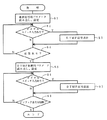
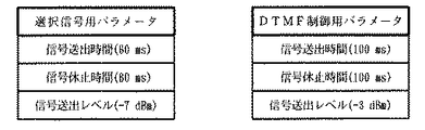
図1は、本発明の一実施例である電話機の動作を示すフローチャートである。使用者が受話器を取る(オフフック)と、図示しない電話機の制御装置は回線を閉じて発呼する。ステップS1においては、制御装置は選択信号(ダイヤル信号)用のDTMF送出パラメータ(信号送出時間、信号休止時間、信号送出レベル等)を読み出し、DTMF信号送出回路に設定する。図4左には、選択信号用パラメータの一例が示されている。ステップS2においては、制御装置はダイヤルスイッチのいずれかが押下(入力)されたか否かを判定し、判定結果が肯定であればステップS3に移行する。ステップS3においては、DTMF信号送出回路は、設定されたパラメータに基づき、押下されたスイッチに対応するDTMF信号を送出する。ステップS4においては、制御回路は例えば回線の極性が反転したか否かにより相手端末の応答を判定し、判定結果が否定であればステップS2に戻るが、肯定であればステップS5に移行する。
【0008】
ステップS5においては、制御装置はDTMF制御用パラメータを読み出し、DTMF信号送出回路に設定する。図4右にはDTMF制御用パラメータの一例が示されている。ステップS6においては、ダイヤルスイッチの入力があったか否かが判定され、結果が肯定であればステップS7に移行して、設定されたパラメータに基づき、DTMF信号が送出される。ステップS8においては、オンフックあるいは回線断が検出されたか否かが判定され、結果が否定の場合にはステップS6に戻るが、肯定の場合には処理を終了する。なおステップS4の応答ありの判定の代わりに、例えば電話機にパラメータ切り替え用のスイッチを設け、該スイッチが操作されたか否かを判定するようにしてもよい。この場合、使用者はダイヤル終了後に該スイッチを操作し、その後にDTMF制御を行う。以上の構成により、ダイヤル後に異なるパラメータでDTMF信号の送出が可能となり、相手装置にDTMF信号を確実に検出させることができる。
【0009】
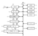
図3は本発明の第2の実施例であるファクシミリ装置の構成を示すブロック図である。CPU1は、ファクシミリ装置全体の制御処理、およびファクシミリ伝送制御手順処理を行う。ROM2はファクシミリ全体を制御するプログラムが格納されている不揮発性メモリであり、RAM3は制御プログラムのワークエリヤとして使用されるメモリである。RTC4は時計回路(リアルタイムクロック)である。キーボード5はパネルに装備されているスイッチからなる入力装置であり、ディスプレイ6は例えば液晶(LCD)を用いた文字、図形の表示装置である。スキャナ7は、例えばCCDイメージセンサ等を用いて送信原稿を読み取る装置であり、プリンタ8は受信画像データ等をプリントする装置である。
画情報メモリ9は、画情報を蓄積する大容量のメモリであり、コーダ/デコーダ10は画情報を符号化(圧縮)、復号化(伸張)する回路である。符号化画情報メモリ11は符号化された画情報を記憶するメモリである。モデム12は、ファクシミリ伝送制御信号用の低速モデム(V21)と画情報の送受信用の高速モデム(V27ter 、V29、V33、V17など)機能を備えた変復調装置である。また、このモデムはDTMF信号(PB信号)の送受信機能を備えており、送出信号レベルも制御可能なものである。この機能はDTMF信号によるコマンドの送受信と共にPB回線へのダイヤル時にも使用される。NCU13は電話網やISDNの回線とのインターフェース回路であり、自動発着信機能を備えている。14は通信網の加入者回線であり、バス15は装置内の各回路間でデータの転送を行うためのものである。なお、図3において太い矢印は画情報の流れを示している。
【0010】
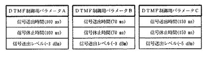
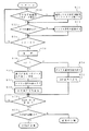
次に動作を説明する。図6は、本発明を適用したファクシミリ装置の発呼処理を示すフローチャートである。ステップS10においては、キーボードからDTMF信号制御用パラメータの指定操作がなされたか否かが判定され、結果が肯定の場合にはステップS11に移行して、選択されたDTMF制御用パラメータセットを記憶する。図5は、予めメモリ内に記憶された複数のパラメータセットの一例を示す説明図であり、オペレータがキーボードによりこの内の1つのパラメータセットを指定、選択することができる。
【0011】
ステップS12においては、ダイヤル番号が入力されたか否かが判定され、結果が肯定であればステップS13に移行して、入力されたダイヤル番号情報を記憶する。入力された番号が短縮番号であれば、短縮ダイヤルリストからダイヤル番号を読み出して記憶する。ステップS14においては、例えばスタートスイッチが押下されたか否かにより、スタートするか否かが判定される。ステップS15においては、NCUが制御され、回線を閉じることによって発呼する。ステップS16においては、回線のダイヤル信号形式がDP(ダイヤルパルス)であるか否かが判定され、結果が肯定であればステップS20に移行し、ステップS13で記憶したダイヤル番号を読み出す。ステップS21においては、該番号に従ってDP信号を送出する。なお回線のダイヤル信号種別は予めオペレータが設定、記憶させてしておく。
【0012】
ステップS16の判定結果が否定の場合にはステップS17に移行し、選択信号用パラメータセットを読み出して、信号送出制御手段に設定する。ステップS18においては、ダイヤル番号を読み出し、ステップS19においては、ステップS17で設定されたパラメータに従ってDTMF信号を送出する。ステップS22においては、相手装置からのNSF/DIS信号の受信を待ち、ステップS23においては、DTMF手順を実行するか否かが判定される。この判定は、例えば図示しないDTMFコード記憶部に送出すべきコードがセットされているか否かによって判定できる。そして結果が否定の場合には通常のファクシミリ手順を実行するが、肯定の場合にはDTMF手順に移行する。
【0013】
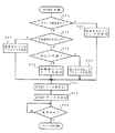
図7は、DTMF手順処理を示すフローチャートである。ステップS24においては、ステップS10、11におけるパラメータ指定があったか否かが判定され、結果が肯定であればステップS25に移行して、指定されたパラメータセットを読み出して、信号送出制御手段に設定する。ステップS26においては、DTMF信号制御パラメータセットが、例えば短縮ダイヤルまたは短縮ダイヤル用メモリに登録されている等の手段により、予め設定されているか否かが判定される。そして結果が肯定の場合にはステップS27に移行し、指定されているパラメータセットを信号送出制御手段に設定する。ステップS28においては、通信相手が外国であるか否かが、例えば電話番号により判定され、結果が肯定の場合にはステップS29に移行して、予め記憶されている国−パラメータセット対応テーブルを参照するなどして、国あるいは地域ごとに対応したパラメータセットを設定する。
【0014】
ステップS28の判定結果が否定の場合にはステップS30に移行し、初期値のパラメータセットを設定する。但しこのパラメータセットは例えば図4右に示されているようなものであり、当然選択信号用パラメータとは異なる。ステップS31においては、DTMFコード記憶部から送出すべきDTMFコードデータを読み出し、ステップS32においては、設定されたパラメータに従って、読み出されたデータに対応したDTMF信号を送出する。ステップS33においては、相手装置からの応答信号を待ち、通常のフェーズB手順に移行する。以上の様な処理により、相手装置に最適なパラメータでDTMF信号を送出することが可能となる。
【0015】
以上、実施例を説明したが、本発明は以下に示すような変形例も考えられる。DTMFコード情報はダイヤル番号と別に記憶する例を開示したが、例えば短縮ダイヤルリストに電話番号とDTMFコードとを区切りコードを挟んで直列に記憶し、区切りコードまでをダイヤル番号として読み出し、区切りコード以降をDTMFコードとして読み出すようにしてもよい。本発明は電話機、ファクシミリ装置に限らず、電話回線を利用した遠隔監視制御装置など、通信回線を介して多重周波信号を送受信する装置一般に適用可能である。
【0016】
【発明の効果】
第1の発明においては、例えば外国(仕様)の装置に対して、ダイヤル時と異なる外国仕様のパラメータを用いて多重周波信号を送出可能であり、多重周波信号を確実に相手装置に検出させることができる。第2の発明においては、伝送路の品質の悪い通信網を経由する通信に対しても、適切なレベルで信号を送出することにより、受信側装置に多重周波信号を確実に検出させることが可能となる。第3の発明においては、着信側の複数の装置に対応する複数のパラメータセットを記憶し、使用するパラメータを選択可能としたので、任意の端末に最適なパラメータで多重周波信号を送出可能となる。従って、第1ないし第3発明によれば、多重周波制御の成功率が向上し、無効な通信が減少するので、多重周波制御機能の活用により通信効率が向上し、また通信費用の削減が図れる。
【図面の簡単な説明】
【図1】第1実施例である電話機の動作を示すフローチャートである。
【図2】通信網の一例を示すブロック図である。
【図3】第2実施例のファクシミリ装置の構成を示すブロック図である。
【図4】各種パラメータセットの一例を示す説明図である。
【図5】複数のパラメータセットの一例を示す説明図である。
【図6】第2実施例であるファクシミリ装置の発呼処理を示すフローチャートである。
【図7】DTMF手順処理を示すフローチャートである。
【符号の説明】
1…CPU、2…ROM、3…RAM、4…RTC、5…キーボード、6…ディスプレイ、7…スキャナ、8…プリンタ、9…画情報メモリ、10…コーダ/デコーダ、11…符号化画情報メモリ、12…モデム、13…NCU、14…回線、15…バス[0001]
[Industrial applications]
The present invention relates to a communication device connected to a communication network, and more particularly to a signal control method in a communication device having a function of transmitting a multi-frequency signal.
[0002]
[Prior art]
In recent years, many devices using a DTMF (dual tone multiple frequency: multiple frequency) signal, that is, a so-called PB signal have been proposed. For example, in a facsimile apparatus, after being connected to a partner apparatus, the partner apparatus can be controlled by using a DTMF signal to instruct confidential polling, confidential transmission, relay broadcast, and the like (Japanese Patent Laid-Open No. 63-104572, JP-A-63-300669, JP-A-2-50560, JP-A-3-260875, and the like. Most of these are manually transmitted by an operator, but a technique for automatically transmitting a DTMF signal has also been proposed (Japanese Patent Laid-Open No. 4-168882).
[0003]
[Problems to be solved by the invention]
In the conventional facsimile apparatus as described above, when dialing a telephone network (exchange) and transmitting a DTMF signal to a partner apparatus, parameters such as a signal transmission time, a signal pause time, and a signal transmission level have the same specifications. Signals were sent using parameters. For example, assuming that the general signal transmission time and the minimum pause (signal pause time) for the Japanese telephone network are 60 milliseconds, respectively, if a signal is transmitted so as to satisfy this standard, the dial signal is correctly received. Will. However, depending on the DTMF signal receiving capability (specification) of the connected partner device, the DTMF signal may not be correctly detected. This is remarkable when the partner device exists overseas (a partner device designed and manufactured according to overseas specifications). For example, Germany specifies a signal transmission time and a signal pause time of 80 to 100 milliseconds, respectively. Therefore, in the facsimile apparatus of the German specification, there is a problem that the signal having the signal transmission time and the signal pause time of 60 milliseconds as described above is not detected, and the control by the DTMF is impossible.
[0004]
Also, the transmitted DTMF signal may not be correctly transmitted to the partner device due to attenuation, deterioration, or noise. FIG. 2 is a block diagram illustrating an example of a communication network. The dial signal is transmitted from the
SUMMARY OF THE INVENTION It is an object of the present invention to solve the above-mentioned problems of the prior art and to provide a communication device capable of reliably transmitting a DTMF signal.
[0005]
[Means for Solving the Problems]
According to a first aspect of the present invention, in a communication device, a means for inputting code information, a transmitting means for transmitting a multi-frequency signal based on the input code, and a dial for a communication network and a time other than a dial for a communication network, Transmission control means for setting at least one of the signal transmission time and the signal pause time of the multi-frequency signal to different values is provided. According to a second aspect of the present invention, in the communication device, a means for inputting code information, a transmitting means for transmitting a multi-frequency signal based on the input code, a time for dialing a communication network and a time other than for a communication network. And transmission control means for setting the signal transmission levels of the multi-frequency signal to different values. In a third aspect based on the first or second aspect, further, parameter set storage means for storing a plurality of parameter sets each including at least one of a signal transmission time, a signal pause time, and a signal transmission level, Parameter set selecting means for selecting a parameter set to be used.
[0006]
[Action]
In the first invention, for example, a multi-frequency signal can be transmitted to a foreign (specification) device using a parameter of a foreign specification different from that used when dialing, and the multi-frequency signal can be reliably detected by a partner device. Can be. According to the second aspect of the present invention, a signal at an appropriate level is transmitted even for communication via a communication network having a poor transmission path, so that the receiving apparatus can reliably detect a multi-frequency signal. It becomes. In the third aspect, since a plurality of parameter sets corresponding to a plurality of devices on the receiving side are stored and parameters to be used can be selected, a multi-frequency signal can be transmitted to any terminal with optimal parameters. .
[0007]
【Example】
Hereinafter, embodiments of the present invention will be described in detail with reference to the drawings.
FIG. 1 is a flowchart showing the operation of the telephone according to one embodiment of the present invention. When the user picks up the telephone (off-hook), the telephone control device (not shown) closes the line and makes a call. In step S1, the control device reads DTMF transmission parameters (signal transmission time, signal pause time, signal transmission level, etc.) for a selection signal (dial signal) and sets them in the DTMF signal transmission circuit. An example of the selection signal parameters is shown on the left side of FIG. In step S2, the control device determines whether or not any of the dial switches has been pressed (input). If the determination result is affirmative, the process proceeds to step S3. In step S3, the DTMF signal transmission circuit transmits a DTMF signal corresponding to the pressed switch based on the set parameters. In step S4, the control circuit determines the response of the partner terminal based on, for example, whether or not the polarity of the line has been reversed. If the determination result is negative, the process returns to step S2;
[0008]
In step S5, the control device reads the DTMF control parameters and sets them in the DTMF signal transmission circuit. An example of DTMF control parameters is shown on the right side of FIG. In step S6, it is determined whether or not an input from the dial switch has been made. If the result is affirmative, the process proceeds to step S7, where a DTMF signal is transmitted based on the set parameters. In step S8, it is determined whether on-hook or line disconnection is detected. If the result is negative, the process returns to step S6, but if affirmative, the process ends. Instead of determining in step S4 that there is a response, for example, a telephone may be provided with a switch for switching parameters, and it may be determined whether the switch has been operated. In this case, the user operates the switch after dialing is completed, and then performs DTMF control. With the above configuration, it is possible to transmit a DTMF signal with different parameters after dialing, and it is possible to make the other device detect the DTMF signal reliably.
[0009]
FIG. 3 is a block diagram showing a configuration of a facsimile apparatus according to a second embodiment of the present invention. The
The image information memory 9 is a large-capacity memory that stores image information, and the coder /
[0010]
Next, the operation will be described. FIG. 6 is a flowchart showing a calling process of the facsimile apparatus to which the present invention is applied. In step S10, it is determined whether or not a designation operation of a DTMF signal control parameter has been performed from the keyboard. If the result is affirmative, the process proceeds to step S11 to store the selected DTMF control parameter set. FIG. 5 is an explanatory diagram showing an example of a plurality of parameter sets stored in the memory in advance. The operator can designate and select one of the parameter sets from the keyboard.
[0011]
In step S12, it is determined whether or not a dial number has been input. If the result is positive, the process shifts to step S13 to store the input dial number information. If the input number is an abbreviated number, the dial number is read from the abbreviated dial list and stored. In step S14, whether or not to start is determined based on, for example, whether or not the start switch has been pressed. In step S15, the NCU is controlled and calls are made by closing the line. In step S16, it is determined whether or not the dial signal format of the line is DP (dial pulse). If the result is affirmative, the process proceeds to step S20, and the dial number stored in step S13 is read. In step S21, a DP signal is transmitted according to the number. The dial signal type of the line is set and stored in advance by the operator.
[0012]
If the decision result in the step S16 is negative, the process shifts to a step S17, where the selection signal parameter set is read and set in the signal transmission control means. In step S18, the dial number is read, and in step S19, a DTMF signal is transmitted according to the parameters set in step S17. In step S22, reception of the NSF / DIS signal from the partner device is waited, and in step S23, it is determined whether to execute the DTMF procedure. This determination can be made based on, for example, whether or not a code to be transmitted is set in a DTMF code storage unit (not shown). If the result is negative, the normal facsimile procedure is executed. If the result is positive, the procedure shifts to the DTMF procedure.
[0013]
FIG. 7 is a flowchart showing the DTMF procedure processing. In step S24, it is determined whether or not the parameters have been specified in steps S10 and S11. If the result is positive, the process proceeds to step S25, where the specified parameter set is read out and set in the signal transmission control means. In step S26, it is determined whether or not the DTMF signal control parameter set has been set in advance by means such as being registered in a speed dial or a speed dial memory. If the result is affirmative, the process shifts to step S27 to set the designated parameter set in the signal transmission control means. In step S28, it is determined whether or not the communication partner is a foreign country based on, for example, a telephone number. If the result is affirmative, the process proceeds to step S29 to refer to a previously stored country-parameter set correspondence table. By doing so, a parameter set corresponding to each country or region is set.
[0014]
If the decision result in the step S28 is negative, the process shifts to a step S30 to set an initial parameter set. However, this parameter set is, for example, as shown on the right side of FIG. 4, and is different from the selection signal parameters. In step S31, DTMF code data to be transmitted is read from the DTMF code storage unit, and in step S32, a DTMF signal corresponding to the read data is transmitted in accordance with the set parameters. In step S33, the process waits for a response signal from the partner device, and proceeds to a normal phase B procedure. With the above processing, it becomes possible to transmit the DTMF signal with the optimal parameters for the partner device.
[0015]
Although the embodiments have been described above, the present invention may have the following modifications. Although an example in which the DTMF code information is stored separately from the dial number is disclosed, for example, a telephone number and a DTMF code are stored in series in a speed dial list with a delimiter code interposed therebetween, and up to the delimiter code is read out as a dial number. May be read as a DTMF code. The present invention is applicable not only to telephones and facsimile apparatuses but also to general apparatuses for transmitting and receiving multi-frequency signals via a communication line, such as a remote monitoring control apparatus using a telephone line.
[0016]
【The invention's effect】
In the first invention, for example, a multi-frequency signal can be transmitted to a foreign (specification) device by using a parameter of a foreign specification different from that at the time of dialing, and the multi-frequency signal can be reliably detected by a partner device. Can be. According to the second aspect of the present invention, a signal at an appropriate level is transmitted even for communication via a communication network having a poor transmission path, so that the receiving-side device can reliably detect a multi-frequency signal. It becomes. In the third aspect, since a plurality of parameter sets corresponding to a plurality of devices on the receiving side are stored and parameters to be used can be selected, a multi-frequency signal can be transmitted to an arbitrary terminal with optimal parameters. . Therefore, according to the first to third aspects of the present invention, the success rate of the multi-frequency control is improved, and invalid communication is reduced. Therefore, the communication efficiency is improved by utilizing the multi-frequency control function, and the communication cost can be reduced. .
[Brief description of the drawings]
FIG. 1 is a flowchart illustrating an operation of a telephone according to a first embodiment.
FIG. 2 is a block diagram illustrating an example of a communication network.
FIG. 3 is a block diagram illustrating a configuration of a facsimile apparatus according to a second embodiment.
FIG. 4 is an explanatory diagram showing an example of various parameter sets.
FIG. 5 is an explanatory diagram showing an example of a plurality of parameter sets.
FIG. 6 is a flowchart showing a calling process of the facsimile apparatus according to the second embodiment.
FIG. 7 is a flowchart showing DTMF procedure processing.
[Explanation of symbols]
DESCRIPTION OF
Claims (3)
Priority Applications (2)
| Application Number | Priority Date | Filing Date | Title |
|---|---|---|---|
| JP17979394A JP3550737B2 (en) | 1994-07-08 | 1994-07-08 | Communication device |
| US08/842,087 US5781626A (en) | 1994-07-08 | 1997-04-28 | Communication device capable of controlling transmission parameters of outputted DTMF signals |
Applications Claiming Priority (1)
| Application Number | Priority Date | Filing Date | Title |
|---|---|---|---|
| JP17979394A JP3550737B2 (en) | 1994-07-08 | 1994-07-08 | Communication device |
Publications (2)
| Publication Number | Publication Date |
|---|---|
| JPH0823426A JPH0823426A (en) | 1996-01-23 |
| JP3550737B2 true JP3550737B2 (en) | 2004-08-04 |
Family
ID=16071998
Family Applications (1)
| Application Number | Title | Priority Date | Filing Date |
|---|---|---|---|
| JP17979394A Expired - Fee Related JP3550737B2 (en) | 1994-07-08 | 1994-07-08 | Communication device |
Country Status (2)
| Country | Link |
|---|---|
| US (1) | US5781626A (en) |
| JP (1) | JP3550737B2 (en) |
Families Citing this family (9)
| Publication number | Priority date | Publication date | Assignee | Title |
|---|---|---|---|---|
| US5907597A (en) | 1994-08-05 | 1999-05-25 | Smart Tone Authentication, Inc. | Method and system for the secure communication of data |
| US6151514A (en) * | 1998-04-22 | 2000-11-21 | Nortel Networks Corporation | Method and apparatus for normalizing DTMF messages from a cellular mobile station |
| US20020186833A1 (en) * | 2001-03-29 | 2002-12-12 | Lucas Phillip W. | System and method of communicating via an in-band tone messaging protocol |
| DE10203224B4 (en) * | 2002-01-28 | 2007-10-31 | Siemens Ag | Management procedure for parameter sets for a parameterizable device |
| DE60231384D1 (en) * | 2002-07-05 | 2009-04-16 | Hewlett Packard Co | Improvements for DTMF signaling |
| US20060106857A1 (en) * | 2004-11-12 | 2006-05-18 | Lillibridge Mark D | Method and system for assured document retention |
| US9195665B2 (en) * | 2006-04-28 | 2015-11-24 | Hewlett-Packard Development Company, L.P. | Method and system for data retention |
| CN102843454B (en) * | 2012-09-04 | 2016-11-02 | 惠州Tcl移动通信有限公司 | Wireless telecommunications system and dual-tone multifrequency data inputting method thereof |
| CN117880409B (en) * | 2024-03-11 | 2024-07-16 | 荣耀终端有限公司 | Communication method, device, chip and storage medium |
Family Cites Families (12)
| Publication number | Priority date | Publication date | Assignee | Title |
|---|---|---|---|---|
| JPS63104572A (en) * | 1986-10-21 | 1988-05-10 | Fujitsu Ltd | Facsimile equipment |
| JPS63300669A (en) * | 1987-05-29 | 1988-12-07 | Nec Corp | Facsimile reply device |
| US5010569A (en) * | 1988-08-03 | 1991-04-23 | Matsushita Electric Industrial Co., Ltd. | Telephone-call distributor |
| JPH0250560A (en) * | 1988-08-12 | 1990-02-20 | Fuji Xerox Co Ltd | Facsimile equipment |
| JPH02105796A (en) * | 1988-10-14 | 1990-04-18 | Matsushita Electric Ind Co Ltd | private branch exchange |
| JPH03260875A (en) * | 1990-03-12 | 1991-11-20 | Sanyo Electric Co Ltd | Picture information filing device |
| JPH04168862A (en) * | 1990-11-01 | 1992-06-17 | Fujitsu Ltd | Communication equipment |
| JP3043497B2 (en) * | 1991-11-14 | 2000-05-22 | キヤノン株式会社 | Telephone equipment |
| US5327492A (en) * | 1992-04-30 | 1994-07-05 | At&T Bell Laboratories | Method for selectively controlling the propagation of dual-tone multi-frequency signals within a telecommunications network |
| US5369697A (en) * | 1993-04-30 | 1994-11-29 | Boston Technology, Inc. | Method and apparatus for automatically switching between pulse code and DTMF signals generated by a telephone |
| US5422945A (en) * | 1993-07-16 | 1995-06-06 | American Express Trs | Fast last digit detection of a dialed telephone number |
| US5416835A (en) * | 1993-07-19 | 1995-05-16 | At&T Corp. | Automatic signaling-type indicator for use in subsequent interactive dialing |
-
1994
- 1994-07-08 JP JP17979394A patent/JP3550737B2/en not_active Expired - Fee Related
-
1997
- 1997-04-28 US US08/842,087 patent/US5781626A/en not_active Expired - Lifetime
Also Published As
| Publication number | Publication date |
|---|---|
| JPH0823426A (en) | 1996-01-23 |
| US5781626A (en) | 1998-07-14 |
Similar Documents
| Publication | Publication Date | Title |
|---|---|---|
| JP3550737B2 (en) | Communication device | |
| US5309507A (en) | Data communication apparatus for maintaining data integrity during an interruption request | |
| US5692036A (en) | Facsimile apparatus having auto calling function | |
| JP3267676B2 (en) | Facsimile apparatus and facsimile communication method | |
| JP2533105B2 (en) | Facsimile machine | |
| JP3430654B2 (en) | Facsimile machine | |
| JPH05199387A (en) | Communication start speed control method | |
| JP3757721B2 (en) | Facsimile communication device | |
| JPS62234456A (en) | data communication equipment | |
| JP2001339591A (en) | Communication terminal | |
| JP3870544B2 (en) | Communication terminal device | |
| JP3659434B2 (en) | Facsimile device | |
| JP3053210B2 (en) | Facsimile machine | |
| JP2000244677A (en) | Communication device and communication control device | |
| JP2954318B2 (en) | Facsimile machine | |
| JP2989633B2 (en) | Facsimile machine | |
| JPH1169033A (en) | Facsimile equipment | |
| KR100292090B1 (en) | Method for automatically controlling automatic redial times in accordance with the ratio for successing connection of automatic transmission in a facsimile machine | |
| JP3794404B2 (en) | Communication terminal device | |
| JP3426858B2 (en) | Cordless telephone | |
| JPH04299637A (en) | Communication device and communication method | |
| JPH07221957A (en) | Communication control device for facsimile machine | |
| JPH0483456A (en) | facsimile machine | |
| JPH06105107A (en) | Fax machine | |
| JPH0715495A (en) | Telephone line type automatic switching device |
Legal Events
| Date | Code | Title | Description |
|---|---|---|---|
| TRDD | Decision of grant or rejection written | ||
| A01 | Written decision to grant a patent or to grant a registration (utility model) |
Free format text: JAPANESE INTERMEDIATE CODE: A01 Effective date: 20040330 |
|
| A61 | First payment of annual fees (during grant procedure) |
Free format text: JAPANESE INTERMEDIATE CODE: A61 Effective date: 20040412 |
|
| R150 | Certificate of patent or registration of utility model |
Free format text: JAPANESE INTERMEDIATE CODE: R150 |
|
| FPAY | Renewal fee payment (event date is renewal date of database) |
Free format text: PAYMENT UNTIL: 20080514 Year of fee payment: 4 |
|
| FPAY | Renewal fee payment (event date is renewal date of database) |
Free format text: PAYMENT UNTIL: 20090514 Year of fee payment: 5 |
|
| FPAY | Renewal fee payment (event date is renewal date of database) |
Free format text: PAYMENT UNTIL: 20100514 Year of fee payment: 6 |
|
| FPAY | Renewal fee payment (event date is renewal date of database) |
Free format text: PAYMENT UNTIL: 20110514 Year of fee payment: 7 |
|
| FPAY | Renewal fee payment (event date is renewal date of database) |
Free format text: PAYMENT UNTIL: 20120514 Year of fee payment: 8 |
|
| FPAY | Renewal fee payment (event date is renewal date of database) |
Free format text: PAYMENT UNTIL: 20130514 Year of fee payment: 9 |
|
| FPAY | Renewal fee payment (event date is renewal date of database) |
Free format text: PAYMENT UNTIL: 20130514 Year of fee payment: 9 |
|
| FPAY | Renewal fee payment (event date is renewal date of database) |
Free format text: PAYMENT UNTIL: 20140514 Year of fee payment: 10 |
|
| LAPS | Cancellation because of no payment of annual fees |