JP3550552B2 - refrigerator - Google Patents
refrigerator Download PDFInfo
- Publication number
- JP3550552B2 JP3550552B2 JP2001138235A JP2001138235A JP3550552B2 JP 3550552 B2 JP3550552 B2 JP 3550552B2 JP 2001138235 A JP2001138235 A JP 2001138235A JP 2001138235 A JP2001138235 A JP 2001138235A JP 3550552 B2 JP3550552 B2 JP 3550552B2
- Authority
- JP
- Japan
- Prior art keywords
- machine room
- condenser
- refrigerator
- compressor
- blower
- Prior art date
- Legal status (The legal status is an assumption and is not a legal conclusion. Google has not performed a legal analysis and makes no representation as to the accuracy of the status listed.)
- Expired - Fee Related
Links
Images


Classifications
-
- F—MECHANICAL ENGINEERING; LIGHTING; HEATING; WEAPONS; BLASTING
- F25—REFRIGERATION OR COOLING; COMBINED HEATING AND REFRIGERATION SYSTEMS; HEAT PUMP SYSTEMS; MANUFACTURE OR STORAGE OF ICE; LIQUEFACTION SOLIDIFICATION OF GASES
- F25D—REFRIGERATORS; COLD ROOMS; ICE-BOXES; COOLING OR FREEZING APPARATUS NOT OTHERWISE PROVIDED FOR
- F25D23/00—General constructional features
- F25D23/003—General constructional features for cooling refrigerating machinery
-
- F—MECHANICAL ENGINEERING; LIGHTING; HEATING; WEAPONS; BLASTING
- F25—REFRIGERATION OR COOLING; COMBINED HEATING AND REFRIGERATION SYSTEMS; HEAT PUMP SYSTEMS; MANUFACTURE OR STORAGE OF ICE; LIQUEFACTION SOLIDIFICATION OF GASES
- F25D—REFRIGERATORS; COLD ROOMS; ICE-BOXES; COOLING OR FREEZING APPARATUS NOT OTHERWISE PROVIDED FOR
- F25D2323/00—General constructional features not provided for in other groups of this subclass
- F25D2323/002—Details for cooling refrigerating machinery
- F25D2323/0026—Details for cooling refrigerating machinery characterised by the incoming air flow
- F25D2323/00264—Details for cooling refrigerating machinery characterised by the incoming air flow through the front bottom part
-
- F—MECHANICAL ENGINEERING; LIGHTING; HEATING; WEAPONS; BLASTING
- F25—REFRIGERATION OR COOLING; COMBINED HEATING AND REFRIGERATION SYSTEMS; HEAT PUMP SYSTEMS; MANUFACTURE OR STORAGE OF ICE; LIQUEFACTION SOLIDIFICATION OF GASES
- F25D—REFRIGERATORS; COLD ROOMS; ICE-BOXES; COOLING OR FREEZING APPARATUS NOT OTHERWISE PROVIDED FOR
- F25D2323/00—General constructional features not provided for in other groups of this subclass
- F25D2323/002—Details for cooling refrigerating machinery
- F25D2323/0026—Details for cooling refrigerating machinery characterised by the incoming air flow
- F25D2323/00266—Details for cooling refrigerating machinery characterised by the incoming air flow through the bottom
-
- F—MECHANICAL ENGINEERING; LIGHTING; HEATING; WEAPONS; BLASTING
- F25—REFRIGERATION OR COOLING; COMBINED HEATING AND REFRIGERATION SYSTEMS; HEAT PUMP SYSTEMS; MANUFACTURE OR STORAGE OF ICE; LIQUEFACTION SOLIDIFICATION OF GASES
- F25D—REFRIGERATORS; COLD ROOMS; ICE-BOXES; COOLING OR FREEZING APPARATUS NOT OTHERWISE PROVIDED FOR
- F25D2323/00—General constructional features not provided for in other groups of this subclass
- F25D2323/002—Details for cooling refrigerating machinery
- F25D2323/0027—Details for cooling refrigerating machinery characterised by the out-flowing air
- F25D2323/00274—Details for cooling refrigerating machinery characterised by the out-flowing air from the front bottom
Landscapes
- Devices That Are Associated With Refrigeration Equipment (AREA)
Description
【0001】
【発明の属する技術分野】
本発明は、冷蔵庫に係り、特に機械室に強制通風形の凝縮器を備えた家庭用冷蔵庫に好適なものである。
【0002】
【従来の技術】
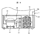
中型や大型の家庭用冷蔵庫(従来技術1)を図9から図11を参照して説明する。
【0003】
この家庭用冷蔵庫は、冷蔵庫箱体1、冷蔵庫扉及び冷凍サイクル等より構成されている。そして、この冷蔵庫箱体1は、鋼板製の外箱、合成樹脂製の内箱及びこれらの間に充填された発泡ウレタン製の断熱材より構成され、複数の貯蔵室を形成している。また、冷蔵庫扉は貯蔵室を開閉するように設けられている。
【0004】
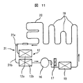
この冷凍サイクルは、図11に示す如く、冷媒を昇圧、循環させる圧縮機16、庫外への放熱を担う熱交換器としての凝縮器18、19、露付防止放熱パイプ20、庫内に設置され貯蔵室の冷却を行なう熱交換器としての蒸発器12、さらにそれらをつなぐキャピラリー21等から構成されている。
【0005】
この凝縮器18、19は、図9に示す冷蔵庫箱体1の背面下部の機械室22に設置されて機械室送風機17により強制的に通風される機械室凝縮器18と、自然対流形の凝縮器として冷蔵庫箱体1の断熱壁内の外表面近くに鋼板製からなる外箱に接触させ冷媒管を埋め込んだ形態の箱体凝縮器19とを併用した形態で構成されている。
【0006】
強制通風形の機械室凝縮器18は、風路の形成や送風機等の動力を必要とするが、庫内への熱侵入を防止することができると共に、冷蔵庫の処分時に凝縮器18を分離することが容易であり、また、高性能化による冷蔵庫の省電力化が図れるといった利点を有している。一方、箱体凝縮器19は、簡単な構造でかつ送風機等の動力を必要としない特徴を有するが、箱体凝縮器19から庫内への熱侵入による性能低下を招くと共に、冷蔵庫の処分時に箱体凝縮器19を断熱壁から分離することが難しくなるという欠点を有する。
【0007】
この強制通風形の機械室凝縮器18としては、図10に示す帯状フィン18cが螺旋巻きされた冷媒管18dを立体状に蛇行曲げした螺旋フィン形凝縮器18が使われるようになっている。この螺旋フィン形凝縮器18は、図9に示す如く、冷蔵庫箱体1の背面下部の機械室22に設置され、機械室22に設置された送風機17により通風される冷却空気28により強制的に冷却される。なお、この従来技術1に関連するものとしては、特開平7−318222号公報に記載されたものがある。
【0008】
一方、実開昭58−119178号公報に記載された冷蔵ショーケース(従来技術2)では、底面部全体に機械室を大きく形成した冷蔵ショーケース箱体と、機械室内の後部に配置した圧縮機と、機械室内の前部に配置したクロスフィンチューブ形凝縮器と、クロスフィンチューブ形凝縮器の吸入部に配置したフィルターと、圧縮機及び凝縮器に強制通風する二つの機械室送風機とを備えている。そして、機械室は、前面下部の角部に傾斜した空気吸入口を形成し、背面下部に空気吐出口を形成している。クロスフィンチューブ形凝縮器は、2列の冷媒管に交差するように多数のフィンを並設したクロスフィンチューブ形熱交換器で構成すると共に、冷媒管が左右に延びてその曲げ部が左右の両側に位置して前方に高く平坦状に傾斜させて配置している。機械室送風機は、ファンダクト板に形成した円孔にマウスリングを有することなく設置したものである。
【0009】
【発明が解決しようとする課題】
しかし、従来技術1では、螺旋フィン形凝縮器18を機械室22の設置スペースに合わせて縦、横、奥行き方向での自由な形状に形成できる利点を有しているが、1つの螺旋フィンに対して上下左右方向でのフィンの接触に伴う擦れ音を防止するために各段及び各列間にて大きな隙間を設ける必要があると共に、機械室を構成する壁面との間にも大きな隙間を設ける必要があり、このために螺旋フィン形凝縮器18の占有体積当たりの伝熱面積が低いものとなっていた。これにより、狭い空間で構成される機械室22内に設置される螺旋フィン形凝縮器18で放熱量を十分に確保して高性能化を図ることが難しく、冷蔵庫の省電力化を図ることが難しいという課題があった。
【0010】
一方、従来技術2は、底面部全体に機械室を大きく形成し、その前面に吸入口及び背面に吐出口を有する冷蔵ショーケースに関するものであり、背面下部の角部に機械室を形成した冷蔵庫とは全く相違している。即ち、従来技術2では、クロスフィン形凝縮器を傾斜させ吸込面積を大きくしてゴミ詰まりによるフィルターの掃除の回数を低減することが示されているが、冷蔵庫のように背面下部の角部に機械室が設けられたものでは、フィルターを機械室に設置した場合に、フィルターを取出すことが困難なように設置されることが多く、その掃除が難しいのが現状である。また従来技術2には、冷蔵庫箱体の背面下部の角部に形成された機械室のような狭い場所で機械室凝縮器の性能を向上して省電力を図ること、これを安価な構成でまたは組立て性を良好にしつつ達成すること、さらには冷蔵庫箱体の横幅変更による容量変更に対応すること等に関しては記載されていない。
【0011】
本発明の目的は、機械室凝縮器の性能を向上して省電力化を図ることができると共に、綿埃等が付着して機械室凝縮器の吸込み側が詰まっても機械室凝縮器性能の低下を抑制して冷蔵庫の運転性能を確保できる冷蔵庫を提供することにある。
【0012】
本発明の別の目的は、安価な構成で、機械室凝縮器の性能を向上して省電力化を図ることができる冷蔵庫を提供することにある。
【0013】
本発明の別の目的は、機械室内の構成部品の組立て性が良好で、機械室凝縮器の性能を向上して省電力化を図ることができる冷蔵庫を提供することにある。
【0014】
本発明の別の目的は、冷蔵庫箱体の横幅変更による容量変更に容易に対応できると共に、機械室凝縮器の性能を向上して省電力化を図ることができる冷蔵庫を提供することにある。
【0015】
【課題を解決するための手段】
上記目的を達成するために、本発明では、背面下部の角部に機械室が配置され、圧縮機、凝縮器及び蒸発器を冷媒管で接続した冷凍サイクルを備えて前記圧縮機及び前記凝縮器を前記機械室に備えた冷蔵庫において、前記機械室は、冷蔵庫箱体の横幅全体にわたって横長に形成されており、前記冷蔵庫箱体、載置板及び機械室カバーによって上面部、前面部、両側面部、底面部、及び背面部が形成されて吸入口と吐出口よりなる通風口を除いて閉塞された空間で構成され、左右方向一側には前記圧縮機が配置され、その左右方向他側には前記凝縮器が配置され、前記圧縮機が配置される空間と前記凝縮器が配置される空間とを仕切り、前記凝縮器から前記圧縮機へ至る通風路を仕切る仕切り板と、この仕切り板のマウスリング部に配置されて前記圧縮機及び前記凝縮器に強制通風する機械室送風機とを備え、前記凝縮器は、蛇行状に形成した冷媒管に多数の板状フィンを並設したクロスフィンチューブ形熱交換器であり、前記機械室の底面部に対向する水平部分と前記機械室の側面部に対向する側面部対向部分とを有し、この水平部分は前記機械室送風機の下方まで延び、この側面対向部分は前記上面部まで延びて構成され、前記凝縮器から前記機械室送風機に至る通風路はその周囲が閉鎖され前記凝縮器のフィン間隙及び前記機械室送風機の隙間が開口する半密閉空間とし、前記機械室の吸入口は前記凝縮器の吸込側に設けられ、前記機械室送風機は、前記仕切り板に設けた前記マウスリング部より前記凝縮器側に突出して配置されるプロペラ形送風機である構成としたことにある。
【0016】
【発明の実態の形態】
以下、本発明の冷蔵庫の各実施例を図を用いて説明する。なお、各実施例及び従来例の図における同一符号は同一物又は相当物を示す。
【0017】
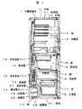
本発明の第1実施例の冷蔵庫の全体構成を図1から図3を参照しながら説明する。図1は本発明の第1実施例による冷蔵庫の縦断面図、図2は図1の冷蔵庫の正面図、図3は図1の冷蔵庫の冷凍サイクル図である。
【0018】
図1及び図2に示すように、冷蔵庫箱体1は、鋼板製の外箱1a、合成樹脂製の内箱1b及びその間に充填された発砲ウレタン製の断熱材1cから構成されており、上から、冷蔵室2、野菜室3、切替室4、製氷室5、冷凍室6が独立して形成されている。それぞれの貯蔵室2〜6には扉7〜11が備えられている。これらの冷蔵室2、野菜室3、切替室4、製氷室5、冷凍室6は、それぞれの通常の一般的な貯蔵室としての機能を備えているものであり、詳細な説明は省略する。
【0019】
そして、冷蔵庫箱体1の背面下部の角部には機械室22が形成され、この機械室22内に圧縮機16、蒸発容器23、機械室送風機17(図4参照)、機械室凝縮器18(図4参照)等が配置されている。この機械室22は、冷蔵庫箱体1で上面壁部、前面壁部及び両側面壁部が形成され、載置板25で底面壁部が形成され、機械室カバー24で背面壁部が形成されている。また、機械室22は、冷蔵庫箱体1の横幅全体にわたって横長に形成されており、吸入口及び吐出口よりなる通風口を除いて閉塞された空間で構成される。この機械室カバー24はネジ等により冷蔵庫箱体1に着脱可能に取付けられている。また、載置板25は外箱1aの下面にネジ等により固定されている。この載置板25には脚26が取付けられており、載置板25と床面27との間には空隙が形成される。
【0020】
冷蔵室側蒸発器12は野菜室3の背面側に配置されている。冷蔵室側送風機13は、冷蔵室側蒸発器12専用の冷気通風用送風機であり、冷蔵室側蒸発器12の蒸発器室中に配置され、冷蔵室側蒸発器12からの冷気を冷蔵室2と野菜室3に供給する。冷凍室側蒸発器14は切替室4、製氷室5、冷凍室6の背面側に配置されている。冷凍室側送風機15は、冷凍室蒸発器14専用の冷気通風用送風機であり、冷凍室蒸発器14の通風路中に配置され、冷凍室蒸発器14からの冷気を切替室4、製氷室5、冷凍室6に供給する。それぞれの蒸発器12、14は、圧縮機16により冷媒が供給され、それぞれ冷凍サイクルの一部を形成して冷却運転が行なわれる。冷蔵室側蒸発器12及び冷凍室側蒸発器14から排出される水は、機械室22内の蒸発容器23に導かれ、圧縮機16で発生する熱を利用して蒸発される。
【0021】
図3に示すように、冷凍サイクルは、圧縮機16、クロスフィンチューブ形熱交換器を用いた機械室凝縮器18、冷媒管埋め込み形の箱体凝縮器19、露付防止放熱パイプ20、第1キャピラリー21a及び冷蔵室側蒸発器12aまたは第2キャピラリー21b及び冷凍室側蒸発器12b、圧縮機16の順に配管にて接続されて冷凍サイクルが構成される。キャピラリー21は第1キャピラリー21aと第2キャピラリー21bとからなり、蒸発器12は第1蒸発器12aと第2蒸発器12bとからなっている。
【0022】
この圧縮機16及び機械室凝縮器18は機械室22に配置されて機械室送風機17により強制通風される。箱体凝縮器19は、冷蔵庫箱体1の断熱壁1c内で外箱1aの一側面に接触させて冷媒管を埋め込んだ形態の自然対流形の凝縮器である。露付防止放熱パイプ20は、冷蔵庫箱体1の前面開口部に沿って外箱1aと断熱材1cとの間に配置され、外箱1aの前面部分への露付を防止するものである。
【0023】
而して、冷媒は、図3矢印に示すように、圧縮機16で圧縮されて高温、高圧となって機械室凝縮器18に至り、機械室凝縮器18で放熱されて温度が下がり、箱体凝縮器19でさらに放熱され、そして露付防止放熱パイプ20で外箱1aの前面を加熱して露付を防止し、第1キャピラリー21aで減圧されて冷蔵室側蒸発器12aに至る流れと第2キャピラリー21bで減圧されて冷凍室側蒸発器12bに至る流れとに分流され、それぞれの冷蔵室側蒸発器12a及び冷凍室側蒸発器12bで蒸発されて周囲から熱を奪い、低温、低圧の状態となって圧縮機16に戻り、以下これを繰り返すことにより冷却運転が行われる。
【0024】
なお、冷蔵室側蒸発器12a及び冷凍室側蒸発器12bへの分流は弁(図示せず)により制御される。また、機械室送風機17は、この冷凍サイクルの運転中に運転され、圧縮機16及び機械室凝縮器18に強制通風してその放熱を行なう。
【0025】
この冷凍サイクルにおいては、後述するようにクロスフィンチューブ形の機械室凝縮器18を用いてその放熱量を増大したことにより、冷蔵庫箱体1の箱体凝縮器19を大幅に削減することができる。従って、箱体凝縮器19から貯蔵室内への熱侵入を大幅に削減することができ、冷蔵庫の省電力化を図ることができると共に、冷蔵庫の処分時における箱体凝縮器19を断熱壁1cから分離することが容易となり、冷蔵庫の処分を容易に行なうことができる。なお、機械室凝縮器18の放熱量をさらに増大することにより、箱体凝縮器19を削減するようにしてもよい。
【0026】
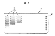
次に、機械室22に係る詳細構成を図4から図7を参照しながら説明する。図4は図1の冷蔵庫の機械室部を示す背面図、図5は同機械室部の背面斜視図、図6は同機械室部に配置される機械室凝縮器の単体状態の斜視図、図7は同機械室部に取付けられる機械室カバーの背面図である。なお、図4及び図5は機械室カバー24を取外した状態を示す。
【0027】
機械室22は、横に長く縦に高い略直方体形状の空間、即ち、奥行き寸法より上下寸法が大きく且つ上下寸法より横幅寸法が大きいい空間で形成している。具体的には、前面壁部の上部が傾斜していると共に、背面中央部が後方に若干突出している。圧縮機16は機械室22の左右方向の一側に配置され、機械室凝縮器18は機械室22の左右方向の他側に配置されている。機械室送風機17は、プロペラ形送風機で構成され、圧縮機16を配置した空間と機械室凝縮器18を配置した空間とを仕切る仕切り板40のマウスリング41部に配置され、具体的には、機械室凝縮器18から圧縮機16に至る通風路を仕切る仕切り板40に設けたマウスリング41より機械室凝縮器18側に軸方向寸法で半分より大きく突出して配置されている。この機械室送風機17は、図4及び図5の矢印28に示すように空気を吸い込み、矢印29に示すように空気を吐出す機能を有し、機械室22内に配置された圧縮機16及び機械室凝縮器18に強制通風する。この機械室凝縮器18から機械室送風機17に至る通風路はその周囲を冷蔵庫箱体1、載置板25、機械室カバー24及び固定具33〜35等により閉鎖して機械室凝縮器18のフィン間隙及び機械室送風機17の隙間が開口する半密閉空間とし、機械室凝縮器18は広い面積を有する面がこの半密閉空間に対面するように配置されている。
【0028】
機械室22への空気の吸い込み部は、図5に示すように、載置板25に形成された底面吸入口30と、冷蔵庫箱体1に形成された箱体吸入口31と、図7に示すように機械室カバー24の一側に形成されたカバー吸入口42とからなっている。この底面吸入口30は機械室送風機17の吸込み側で且つ機械室凝縮器18の水平部18cの下方に位置する載置板25部分に形成された多数のスリット状の開口で形成されている。また、箱体吸入口31は、機械室22に面する冷蔵庫箱体1の角部を切り欠いた通風路で形成され、機械室凝縮器18の吸込側の前方に位置している。また、カバー吸入口42は、機械室凝縮器18の垂直部18dの吸込側に位置する機械室カバー24部分に形成された多数のスリット状の開口で形成されている。
【0029】
そして、機械室22の空気の吐出部は、図7に示すように機械室カバー24に形成されたカバー吐出口43と、図5に示すように機械室22に面する冷蔵庫箱体1の角部を切り欠いた通風路で形成された箱体吐出口32とからなっている。このカバー吐出口43は、機械室送風機17の吐出側に位置する機械室カバー24部分に形成された多数のスリット状の開口で形成されている。また、箱体吐出口32は箱体吸入口31の反対側にほぼ対称的に形成されている。
【0030】
機械室凝縮器18は、図6に単体状態で示すように、冷媒管18a、板状フィン18b、固定具33、34より構成されている。この冷媒管18aは、一つの冷媒管で蛇行状に形成されると共に、1列で形成されている。また、板状フィン18bは、波形フィンで構成され、各列の冷媒管18aが貫通するように多数が並置して設けられ、クロスフィン形熱交換器を構成している。この実施例ではそのフィン間隔が1.5mmであり、フィン間隔の範囲としては1.3mmから1.8mmの範囲が好ましい。さらには、固定具33、34は、板状フィン18bの両側に位置し、冷媒管18aが貫通して両側に突出するように冷媒管18aに固定されている。この冷媒管18aの突出する部分は、別体の曲げパイプで形成して溶接し、これにより蛇行曲げ部を形成している。
【0031】
そして、機械室凝縮器18は、冷媒管18aの長手方向において、それが交差する方向に曲げられて、全体形状が水平部18cと垂直部18dとからなるL字状に形成されている。即ち、機械室凝縮器18の全体形状が左右、前後及び上下方向に延びる立体的な形状となるように折り曲げて形成されている。一側の固定具33は、前部下端部から突出する係止片33aと、後部上端部から突出する係止片33bとを有している。また、他側の固定具34は、係止穴を有する係止片34aと、ネジ穴を有する係止片34bとを有している。板状フィン18bとして波形フィンを用いているので、機械室凝縮器18としての強度が増大し、取付け等を容易に行なうことができる。
【0032】
機械室凝縮器18は、その水平部18cが底面吸入口30に対向するように水平に位置し、その垂直部18dが機械室22の側壁を形成する外箱1aに対向するように垂直に位置して機械室22内に設置される。換言すれば、冷媒管18の蛇行曲げ部が機械室22の上部及び下部に位置すると共に、蛇行状に形成した冷媒管18が前後方向に並ぶように設置されている。従って、冷媒管18aの固定具33から突出する曲げ部は、機械室22の長手方向である横方向に突出し、固定具34から突出する曲げ部は、上方に突出することになる。これにより、冷媒管18aの固定具33、34から突出する部分が機械室22における比較的余裕のある空間に突出することになるので、機械室凝縮器18の収納性が良好となり、大きな機械室凝縮器18を機械室22に収納できることなり、機械室凝縮器18の放熱量を増大することができる。
【0033】
また、機械室凝縮器18の水平部分の端部及び冷媒管18aの突出する部分は機械室送風機17の下方に位置するデッドスペースの部分まで延びている。この点からも機械室凝縮器18の収納性が良好となり、機械室凝縮器18の放熱量を増大することができる。また、機械室送風機17の吸込み側と吹き出し側とを仕切る部分の一部を機械室凝縮器18の固定具33で兼ねることができ、通風構造を簡単なものとすることができる。
【0034】
機械室凝縮器18の具体的な設置構造は、機械室凝縮器18の一側が固定具33を介して載置板25に固定され、機械室凝縮器18の他側が固定具34及び固定具35を介して冷蔵庫箱体1に固定される。このように、載置板25と冷蔵庫箱体1にまたがって機械室凝縮器18を固定することにより、簡単に固定することができる。
【0035】
さらに具体的に機械室凝縮器18の設置構造を説明すると、機械室22の後方(背面側)から機械室凝縮器18を収納し、固定具33の前端部に位置する係止片33aを載置板25の係止穴(図示せず)に挿入して係止し、一側後端部に位置する係止片33bを載置板25の後端部にネジにより固定する。また、固定具34は、固定具35を係止片34a、34bを介して固定し、この固定具35の係止片35aを冷蔵庫箱体1の背面に固定する。このようにして、機械室凝縮器18は冷蔵庫箱体1に固定される。
【0036】
而して、機械室送風機17を運転すると、底面吸入口30から機械室22に吸い込まれた空気28が主に機械室凝縮器18の水平部18cを通って熱交換されると共に、カバー吸入口42及び箱体吸入口31から吸い込まれた空気28が主に機械室凝縮器18の垂直部18dを通って熱交換され、この熱交換された空気28が機械室送風機17から圧縮機16側に吹き出され、その空気29が圧縮機16と熱交換した後に、カバー吐出口43及び箱体吐出口32から機械室22の外部に吐出される。
【0037】
機械室凝縮器18は、板状フィン18b有するクロスフィンチューブ形熱交換器で構成されているため、従来の螺旋フィン形凝縮器よりも占有体積当たりの伝熱面積を著しく大きくすることができ、狭い機械室22内でも大きな放熱量を得ることができる。
【0038】
さらには、機械室凝縮器18は、水平部分と立上げ部分とからなるL字状に形成されているので、通風抵抗の増大を抑えながらその伝熱面積を増大することができ、放熱量を増大することができる。この場合、冷蔵庫箱体1の角部を切り欠いて箱体吸入口31を形成しているので、載置板25に脚26を取付ける部分を確保することや載置板25の強度を確保しながら、吸込面積が増大したL字状の機械室凝縮器18への十分な吸い込み風量を得ることができる。
【0039】
本実施例においては、蛇行状に形成した冷媒管18aに多数の板状フィン18bを並設したクロスフィン形熱交換器を機械室凝縮器18として用い、機械室送風機17により強制通風し、広い面積を有する面が半密閉空間に対面するように機械室凝縮器18を配置しているので、狭い機械室22における占有体積当たりの伝熱面積を増大できると共に、機械室凝縮器18の伝熱性能を高性能化することができ、これにより冷蔵庫の省電力化を図ることができる。特に、機械室凝縮器18の板状フィン18bを波形に形成すると共にそのフィンピッチを1.3mmから1.8mmの範囲内に設定しているので、狭い機械室22内に設置した機械室凝縮器18を適切な通風抵抗で広い伝熱面積及び高い伝熱性能にすることができ、機械室凝縮器18の格段の性能向上を図ることができる。
【0040】
また、仕切り板40に設けたマウスリング41より機械室凝縮器18側に突出して配置したプロペラ形送風機で機械室送風機17を構成すると共に、機械室凝縮器18から機械室送風機17に至る通風路の周囲を閉鎖して機械室凝縮器18のフィン間隙及び機械室送風機17の隙間が開口する半密閉空間とし、更には広い面積を有する面が半密閉空間に対面するように機械室凝縮器18を配置しているので、機械室凝縮器18の吸込み側端面に綿埃が付着して詰まるようなことがあった場合に、機械室凝縮器18から機械室送風機17に至る通風路内の空気をこの通風路内に突出する機械室送風機17により攪拌すると共に、機械室送風機17を通して半密閉空間内への空気の出入が行われ、機械室凝縮器18が半密閉空間側の空気で冷却される。これにより、機械室凝縮器18の吸込側が詰まっても、機械室凝縮器18性能の低下を抑制することができ、冷蔵庫の運転性能を確保することができる。特に、機械室送風機17をマウスリング41より機械室凝縮器18側に軸方向寸法で半分より大きく突出させているので、機械室凝縮器18の吸込み側端面に綿埃等が付着して詰まった場合の機械室送風機17による攪拌及び半密閉空間内への空気の出入を増大することができ、機械室凝縮器18の冷却を格段に向上させることができる。
【0041】
また、蛇行状に形成した冷媒管18aに多数の板状フィン18bを並設したクロスフィン形熱交換器を機械室凝縮器18として用い、奥行き寸法より上下寸法が大きい空間で形成した機械室22に冷媒管18aの蛇行曲げ部が上部及び下部に位置すると共に蛇行状に形成した冷媒管18aが前後方向に並ぶように機械室凝縮器18を設置しているので、伝熱部として直接寄与しない冷媒管18aの蛇行曲げ部が位置する部分の前後幅が小さくなり、狭い機械室22内でも大きな伝熱面積及び通風面積を有する機械室凝縮器18とすることができる。これにより、冷媒管18aの蛇行曲げ部が少なくなって安価な構成にすることができ、しかも機械室凝縮器18の性能が向上し、冷蔵庫の省電力化を図ることができる。特に、機械室凝縮器18の冷媒管18aの曲げ部を別体の曲げパイプで形成して溶接するものにおいては、その溶接個所を低減できることにより大幅なコスト低減を図ることができる。
【0042】
また、蛇行状に形成した冷媒管18aに多数の板状フィン18bを並設したクロスフィン形熱交換器を機械室凝縮器18として用い、その全体形状が左右、前後及び上下方向に延びる立体的な形状となるように折り曲げて形成しているので、狭い機械室22内でも大きな伝熱面積及び大きな通風面積を有する機械室凝縮器18とすることができる。これにより、簡単な構成で、機械室凝縮器18の性能が向上し、冷蔵庫の省電力化を図ることができる。特に、機械室カバーを冷蔵庫箱体に着脱可能に装着すると共に、機械室凝縮器18を機械室22の底面壁部に対向する部分と側面壁部に対向する部分とからなる略L字状に形成しているので、機械室カバーを取外した状態で、機械室送風機17と機械室凝縮器18との間に大きな空間が露出し、この空間を利用して機械室送風機17や機械室凝縮器18等の取付け、取外し等を容易に行なうことができる。また、一列のクロスフィンチューブ形熱交換器で機械室凝縮器18を構成しているので、複数列のクロスフィンチューブ形熱交換器で構成する場合に比較して、通風抵抗が小さく風量を増大することができ、圧縮機16への風量を増大して圧縮機温度を低減させることができる。
【0043】
また、機械室凝縮器18を前記機械室22の底面壁部に対向する水平部18cと側面壁部に対向する垂直部18dからなる略L字状に折り曲げた形状とし、機械室凝縮器18の水平部18cの端部を固定具33を介して載置板25に取付けると共に、その垂直部18dの端部を固定具34、35を介して冷蔵庫箱体1に取付け、機械室凝縮器18の水平部18cと対向する載置板25部分に吸入口30を形成しているので、冷蔵庫の省電力化を図ることができるという効果を奏しつつ、冷蔵庫箱体1の横幅を大きくして容量を増大する冷蔵庫に対して、機械室凝縮器18の水平部18cを延長して大きくすると共に、載置板25の吸入口30をそれに沿って大きく形成することによって、機械室凝縮器18の能力を増大することができ、機械室凝縮器18の取付け構造を大幅に変更することなく、固定具33〜35や製作方法の共用化が可能で、安価に且つ容易に対応することができる。特に、機械室カバー24の左右に吸入口42及び吐出口43を形成しているので、通風抵抗を低減して風量を増大でき、機械室凝縮器18の性能向上を図ることができると共に、冷蔵庫箱体1の横幅を大きくして容量を増大する冷蔵庫に対して、機械室カバー24の左右の吸入口42の及び吐出口43を両側の同じ位置のままで横幅を大きくすることで容易に対応することができる。
【0044】
また、機械室凝縮器18を機械室22の底面壁部に対向する部分と側面壁部に対向する部分とからなる略L字状に形成し、機械室送風機17をマウスリング41より機械室凝縮器18側に突出して配置したプロペラ形送風機で構成すると共に機械室凝縮器18の底面底部に対向する部分の上方に配置しているので、機械室送風機17の軸方向寸法(厚さ)を容易に増やすことができ、風量を増大して凝縮器性能を向上することができる。
【0045】
次に、本発明の第2実施例を図8を用いて説明する。図8は本発明の第2実施例の冷蔵庫の機械室部を示す背面図である。
【0046】
本実施例は、平板状フィン18bが複数列の冷媒管18にまたがって並設されたクロスフィン形熱交換器で平坦状の機械室凝縮器18を構成し、この機械室凝縮器18を機械室送風機17の吸込み側に垂直に設置した点で第1実施例と相違するものであり、その他の点については第1実施例と基本的には同一である。本実施例では、機械室凝縮器18の形状が単純で安価に製作できると共に、横幅の狭い冷蔵庫箱体1に適用することが容易である。
【0047】
【発明の効果】
本発明によれば、機械室凝縮器の性能を向上して省電力化を図ることができると共に、綿埃等が付着して機械室凝縮器の吸込み側が詰まっても機械室凝縮器性能の低下を抑制して冷蔵庫の運転性能を確保できる冷蔵庫が得られるものである。
【0048】
また、本発明によれば、安価な構成で、機械室凝縮器の性能を向上して省電力化を図ることができる冷蔵庫が得られるものである。
【0049】
また、本発明によれば、機械室内の構成部品の組立て性が良好で、機械室凝縮器の性能を向上して省電力化を図ることができる冷蔵庫が得られるものである。
【0050】
また、本発明によれば、冷蔵庫箱体の横幅変更による容量変更に容易に対応できると共に、機械室凝縮器の性能を向上して省電力化を図ることができる冷蔵庫が得られるものである。
【図面の簡単な説明】
【図1】本発明の第1実施例による冷蔵庫の縦断面図である。
【図2】図1の冷蔵庫の正面図である。
【図3】図1の冷蔵庫の冷凍サイクル図である。
【図4】図1の冷蔵庫の機械室部を示す背面図である。
【図5】同機械室部の背面斜視図である。
【図6】同機械室部に配置される機械室凝縮器の単体状態の斜視図である。
【図7】同機械室部に取付けられる機械室カバーの背面図である。
【図8】本発明の第2実施例の冷蔵庫の機械室部を示す背面図である。
【図9】従来の冷蔵庫の機械室部を示す背面図である。
【図10】同冷蔵庫に用いる機械室凝縮器の一部を示す斜視図である。
【図11】同冷蔵庫の冷凍サイクル図である。
【符号の説明】
1…冷蔵庫箱体、1a…外箱、1b…内箱、1c…断熱材、2…冷蔵室、3…野菜室、4…切替室、5…製氷室、6…冷凍室、7〜11…扉、12…冷蔵室側蒸発器、13…冷蔵室側送風機、14…冷凍室側蒸発器、15…冷凍室側送風機、16…圧縮機、17…機械室送風機、18…機械室凝縮器、18a…冷媒管、18b…板状フィン、18c…水平部、18d…垂直部、19…箱体凝縮器、20…露付防止放熱パイプ、21…キャピラリー、21a…第1キャピラリー、21b…第2キャピラリー、22…機械室、23…蒸発容器、24…機械室カバー、25…載置板、26…脚、27…床面、28…吸込側空気、29…吐出側空気、30…底面吸入口、31…箱体吸入口、32…箱体吐出口、33〜35…固定具、40…仕切り板、41…マウスリング、42…カバー吸入口、43…カバー吐出口。[0001]
TECHNICAL FIELD OF THE INVENTION
The present invention relates to a refrigerator, and is particularly suitable for a household refrigerator provided with a forced draft condenser in a machine room.
[0002]
[Prior art]
A medium-sized or large-sized household refrigerator (prior art 1) will be described with reference to FIGS.
[0003]
This home refrigerator includes a
[0004]
As shown in FIG. 11, the refrigeration cycle is provided with a
[0005]
The
[0006]
The forced-ventilation type
[0007]
As the forced ventilation type
[0008]
On the other hand, a refrigerated showcase (prior art 2) described in Japanese Utility Model Application Laid-Open No. 58-119178 discloses a refrigerated showcase box having a large machine room formed on the entire bottom surface, and a compressor disposed at the rear of the machine room. A cross fin tube type condenser arranged at the front of the machine room, a filter arranged at the suction part of the cross fin tube type condenser, and two machine room blowers for forcibly ventilating the compressor and the condenser. ing. In the machine room, an inclined air intake port is formed at the lower front corner, and an air discharge port is formed at the lower rear section. The cross fin tube type condenser is composed of a cross fin tube type heat exchanger in which a number of fins are arranged side by side so as to intersect with two rows of refrigerant tubes, and the refrigerant tubes extend left and right, and the bent portions thereof are left and right. It is located on both sides and is inclined forward and high in a flat shape. The machine room blower is installed without a mouth ring in a circular hole formed in a fan duct plate.
[0009]
[Problems to be solved by the invention]
However, the
[0010]
On the other hand, prior art 2 relates to a refrigerated showcase in which a large machine room is formed on the entire bottom portion, and a suction port is provided on the front surface and a discharge port is provided on the back surface. Is completely different. That is, in the prior art 2, it is shown that the cross-fin type condenser is inclined to increase the suction area to reduce the number of times of cleaning of the filter due to dust clogging. In the case where the machine room is provided, when the filter is installed in the machine room, it is often installed so that it is difficult to take out the filter, and at present, it is difficult to clean the filter. Further, in prior art 2, the performance of the machine room condenser is improved in a narrow place such as the machine room formed at the lower corner of the back of the refrigerator box to save power, and this is realized by an inexpensive configuration. It also does not disclose achieving a good assemblability while coping with a change in capacity by changing the width of the refrigerator box.
[0011]
SUMMARY OF THE INVENTION An object of the present invention is to improve the performance of a machine room condenser to save power, and to reduce the performance of the machine room condenser even if dust is attached to the suction side of the machine room condenser. An object of the present invention is to provide a refrigerator capable of ensuring the operation performance of the refrigerator by suppressing the above.
[0012]
Another object of the present invention is to provide a refrigerator that can improve the performance of a machine room condenser and save power by using an inexpensive configuration.
[0013]
Another object of the present invention is to provide a refrigerator that has good assemblability of components in a machine room, can improve the performance of a machine room condenser, and can save power.
[0014]
Another object of the present invention is to provide a refrigerator that can easily cope with a change in capacity due to a change in the width of the refrigerator box, and can improve the performance of the machine room condenser to save power.
[0015]
[Means for Solving the Problems]
To achieve the above purpose To Departure In the light The machine room is located in the lower rear corner Is placed, Compressor , Refrigeration cycle with compressor and evaporator connected by refrigerant pipe With The compressor and the front Writing Contractor In the refrigerator provided in the machine room, The machine room is formed horizontally long over the entire width of the refrigerator box. An upper surface, a front surface, both side surfaces, a bottom surface, and a back surface are formed by the refrigerator box, the mounting plate, and the machine room cover, and are closed except for a ventilation port including a suction port and a discharge port. Space Left and right side Is The compressor is located And On the other side in the left-right direction Is Previous Writing Contractor But Arrangement Is , A partition plate that partitions a space in which the compressor is disposed and a space in which the condenser is disposed, and a partition plate that partitions a ventilation path from the condenser to the compressor, and is disposed in a mouth ring portion of the partition plate. A compressor and a machine room blower forcibly ventilating the condenser, Previous Writing Contractor , Cross-fin tube type heat exchanger with many plate-like fins arranged side by side in a meandering refrigerant tube Having a horizontal portion facing a bottom portion of the machine room and a side portion facing a side portion of the machine room, the horizontal portion extending below the machine room blower, Is configured to extend to the upper surface portion, Previous Writing The ventilation path from the compressor to the machine room blower is But Closed Is Previous Writing A semi-closed space in which the fin gap of the compressor and the gap of the machine room blower are open, The suction port of the machine room is provided on the suction side of the condenser, and the machine room blower is a propeller-type blower that is disposed so as to protrude toward the condenser side from the mouth ring portion provided on the partition plate. Is that .
[0016]
Embodiment of the present invention
Hereinafter, embodiments of the refrigerator of the present invention will be described with reference to the drawings. The same reference numerals in the drawings of the respective embodiments and the conventional example indicate the same or corresponding components.
[0017]
An overall configuration of a refrigerator according to a first embodiment of the present invention will be described with reference to FIGS. 1 is a longitudinal sectional view of a refrigerator according to a first embodiment of the present invention, FIG. 2 is a front view of the refrigerator of FIG. 1, and FIG. 3 is a refrigeration cycle diagram of the refrigerator of FIG.
[0018]
As shown in FIGS. 1 and 2, the
[0019]
A
[0020]
The refrigerator
[0021]
As shown in FIG. 3, the refrigeration cycle includes a
[0022]
The
[0023]
Then, the refrigerant is compressed by the
[0024]
The flow to the refrigerating
[0025]
In this refrigeration cycle, the amount of heat radiation is increased by using a cross fin tube type
[0026]
Next, a detailed configuration of the
[0027]
The
[0028]
As shown in FIG. 5, the air suction part into the
[0029]
The air discharge portion of the
[0030]
The
[0031]
The machine-
[0032]
The
[0033]
The end of the horizontal portion of the
[0034]
A specific installation structure of the
[0035]
More specifically, the installation structure of the
[0036]
When the
[0037]
Since the
[0038]
Further, since the
[0039]
In this embodiment, a cross-fin type heat exchanger in which a number of plate-
[0040]
Further, the
[0041]
Further, a cross-fin type heat exchanger in which a number of plate-
[0042]
Further, a cross-fin type heat exchanger in which a number of plate-
[0043]
Further, the
[0044]
Further, the
[0045]
Next, a second embodiment of the present invention will be described with reference to FIG. FIG. 8 is a rear view showing the machine room of the refrigerator according to the second embodiment of the present invention.
[0046]
In the present embodiment, a flat
[0047]
【The invention's effect】
ADVANTAGE OF THE INVENTION According to this invention, while the performance of a machine room condenser can be improved and power saving can be achieved, even if dust etc. adhere and the suction side of a machine room condenser is clogged, the deterioration of the machine room condenser performance is reduced. Thus, it is possible to obtain a refrigerator capable of ensuring the operation performance of the refrigerator by suppressing the above.
[0048]
Further, according to the present invention, it is possible to obtain a refrigerator capable of improving the performance of a machine room condenser and saving power with an inexpensive configuration.
[0049]
Further, according to the present invention, it is possible to obtain a refrigerator which has good assemblability of components in a machine room, can improve the performance of a machine room condenser, and can save power.
[0050]
Further, according to the present invention, it is possible to obtain a refrigerator which can easily cope with a change in capacity due to a change in the width of the refrigerator box, and which can improve the performance of the machine room condenser and save power.
[Brief description of the drawings]
FIG. 1 is a longitudinal sectional view of a refrigerator according to a first embodiment of the present invention.
FIG. 2 is a front view of the refrigerator of FIG.
FIG. 3 is a refrigeration cycle diagram of the refrigerator of FIG. 1;
FIG. 4 is a rear view showing a machine room of the refrigerator of FIG. 1;
FIG. 5 is a rear perspective view of the machine room.
FIG. 6 is a perspective view showing a single state of a machine room condenser arranged in the machine room portion.
FIG. 7 is a rear view of a machine room cover attached to the machine room portion.
FIG. 8 is a rear view showing a machine room of a refrigerator according to a second embodiment of the present invention.
FIG. 9 is a rear view showing a machine room of a conventional refrigerator.
FIG. 10 is a perspective view showing a part of a machine room condenser used in the refrigerator.
FIG. 11 is a refrigeration cycle diagram of the refrigerator.
[Explanation of symbols]
DESCRIPTION OF
Claims (5)
前記機械室は、冷蔵庫箱体の横幅全体にわたって横長に形成されており、前記冷蔵庫箱体、載置板及び機械室カバーによって上面部、前面部、両側面部、底面部、及び背面部が形成されて吸入口と吐出口よりなる通風口を除いて閉塞された空間で構成され、左右方向一側には前記圧縮機が配置され、その左右方向他側には前記凝縮器が配置され、前記圧縮機が配置される空間と前記凝縮器が配置される空間とを仕切り、前記凝縮器から前記圧縮機へ至る通風路を仕切る仕切り板と、この仕切り板のマウスリング部に配置されて前記圧縮機及び前記凝縮器に強制通風する機械室送風機とを備え、
前記凝縮器は、蛇行状に形成した冷媒管に多数の板状フィンを並設したクロスフィンチューブ形熱交換器であり、前記機械室の底面部に対向する水平部分と前記機械室の側面部に対向する側面部対向部分とを有し、この水平部分は前記機械室送風機の下方まで延び、この側面対向部分は前記上面部まで延びて構成され、
前記凝縮器から前記機械室送風機に至る通風路はその周囲が閉鎖され前記凝縮器のフィン間隙及び前記機械室送風機の隙間が開口する半密閉空間とし、前記機械室の吸入口は前記凝縮器の吸込側に設けられ、
前記機械室送風機は、前記仕切り板に設けた前記マウスリング部より前記凝縮器側に突出して配置されるプロペラ形送風機である冷蔵庫。Machine room is disposed in a corner portion of the lower back, the compressor, the refrigerator curdled condenser and the compressor evaporator comprises a refrigerating cycle connected by refrigerant pipes and the front Kiko condenser provided in the machine room ,
The machine room is formed to be horizontally long over the entire width of the refrigerator box, and the refrigerator box, the mounting plate, and the machine room cover form a top portion, a front portion, both side portions, a bottom portion, and a back portion. except for vents made of the suction port and the discharge port is composed of a closed space Te, the compressor is disposed in the left-right direction one side, the left and right directions other side is disposed before Kiko condenser, A partition plate that partitions a space in which the compressor is disposed and a space in which the condenser is disposed, and a partition plate that partitions a ventilation path from the condenser to the compressor, and is disposed in a mouth ring portion of the partition plate. A compressor and a machine room blower forcibly ventilating the condenser,
Before Kiko condenser is a cross fin tube type heat exchangers arranged a number of plate-like fins in the refrigerant pipe formed in meandering shape, the machine room and the horizontal portion facing the bottom of the machine room A side portion facing the side portion, the horizontal portion extends below the machine room blower, the side portion extends to the top surface portion,
Before air passage extending from Kiko condenser in the machine chamber blower is a semi-sealed space around the fin gaps and gap opening in the machine room blower Kiko condenser before being closed, the suction port of the machine room Provided on the suction side of the condenser,
The refrigerator, wherein the machine room blower is a propeller-type blower arranged to protrude toward the condenser side from the mouth ring portion provided on the partition plate .
Priority Applications (3)
| Application Number | Priority Date | Filing Date | Title |
|---|---|---|---|
| JP2001138235A JP3550552B2 (en) | 2001-05-09 | 2001-05-09 | refrigerator |
| CNB02107562XA CN1239872C (en) | 2001-05-09 | 2002-03-15 | Refrigerator |
| KR10-2002-0014246A KR100481896B1 (en) | 2001-05-09 | 2002-03-16 | Refrigerator |
Applications Claiming Priority (1)
| Application Number | Priority Date | Filing Date | Title |
|---|---|---|---|
| JP2001138235A JP3550552B2 (en) | 2001-05-09 | 2001-05-09 | refrigerator |
Publications (2)
| Publication Number | Publication Date |
|---|---|
| JP2002333258A JP2002333258A (en) | 2002-11-22 |
| JP3550552B2 true JP3550552B2 (en) | 2004-08-04 |
Family
ID=18985206
Family Applications (1)
| Application Number | Title | Priority Date | Filing Date |
|---|---|---|---|
| JP2001138235A Expired - Fee Related JP3550552B2 (en) | 2001-05-09 | 2001-05-09 | refrigerator |
Country Status (1)
| Country | Link |
|---|---|
| JP (1) | JP3550552B2 (en) |
Families Citing this family (2)
| Publication number | Priority date | Publication date | Assignee | Title |
|---|---|---|---|---|
| JP5773958B2 (en) * | 2012-08-09 | 2015-09-02 | 三菱電機株式会社 | Freezer refrigerator |
| EP2993427B1 (en) * | 2014-09-05 | 2018-03-21 | Samsung Electronics Co., Ltd. | Refrigerator |
-
2001
- 2001-05-09 JP JP2001138235A patent/JP3550552B2/en not_active Expired - Fee Related
Also Published As
| Publication number | Publication date |
|---|---|
| JP2002333258A (en) | 2002-11-22 |
Similar Documents
| Publication | Publication Date | Title |
|---|---|---|
| US8047017B2 (en) | Refrigerator and evaporator mounting structure therefor | |
| CN214039084U (en) | Refrigerator with heat radiation fan arranged in press cabin | |
| CN115493328A (en) | freezer | |
| KR100481896B1 (en) | Refrigerator | |
| CN218846549U (en) | freezer | |
| JP4183053B2 (en) | Air conditioner outdoor unit | |
| CN114076457A (en) | Refrigerator with condenser arranged in press cabin | |
| CN100572999C (en) | Built-in type refrigerator | |
| JP4087086B2 (en) | refrigerator | |
| JP3550552B2 (en) | refrigerator | |
| WO2022037382A1 (en) | Embedded refrigerator | |
| JP2003202176A (en) | refrigerator | |
| CN114076458A (en) | Refrigerator with condenser arranged in press cabin | |
| CN111609623B (en) | Refrigerator with L-shaped condenser | |
| CN218846550U (en) | freezer | |
| JP3702120B2 (en) | Cooling system | |
| JP2008111664A (en) | refrigerator | |
| JP2007024348A (en) | Cooling storage | |
| JP2002333259A (en) | refrigerator | |
| JP3954829B2 (en) | Heat exchanger, heat exchange unit and cooling storage | |
| JP2000337752A (en) | Refrigerator | |
| CN110375481A (en) | Bottom has the refrigerator of Double condenser structure | |
| CN115493329A (en) | freezer | |
| CN110388778B (en) | Finned evaporator for refrigerator and refrigerator | |
| JP5367553B2 (en) | Cooling storage |
Legal Events
| Date | Code | Title | Description |
|---|---|---|---|
| A977 | Report on retrieval |
Free format text: JAPANESE INTERMEDIATE CODE: A971007 Effective date: 20031224 |
|
| A131 | Notification of reasons for refusal |
Free format text: JAPANESE INTERMEDIATE CODE: A131 Effective date: 20040113 |
|
| A521 | Written amendment |
Free format text: JAPANESE INTERMEDIATE CODE: A523 Effective date: 20040315 |
|
| TRDD | Decision of grant or rejection written | ||
| A01 | Written decision to grant a patent or to grant a registration (utility model) |
Free format text: JAPANESE INTERMEDIATE CODE: A01 Effective date: 20040420 |
|
| A61 | First payment of annual fees (during grant procedure) |
Free format text: JAPANESE INTERMEDIATE CODE: A61 Effective date: 20040426 |
|
| FPAY | Renewal fee payment (event date is renewal date of database) |
Free format text: PAYMENT UNTIL: 20090430 Year of fee payment: 5 |
|
| FPAY | Renewal fee payment (event date is renewal date of database) |
Free format text: PAYMENT UNTIL: 20090430 Year of fee payment: 5 |
|
| FPAY | Renewal fee payment (event date is renewal date of database) |
Free format text: PAYMENT UNTIL: 20100430 Year of fee payment: 6 |
|
| FPAY | Renewal fee payment (event date is renewal date of database) |
Free format text: PAYMENT UNTIL: 20110430 Year of fee payment: 7 |
|
| LAPS | Cancellation because of no payment of annual fees |