JP3549032B2 - Support column holding patient support means - Google Patents
Support column holding patient support means Download PDFInfo
- Publication number
- JP3549032B2 JP3549032B2 JP16749995A JP16749995A JP3549032B2 JP 3549032 B2 JP3549032 B2 JP 3549032B2 JP 16749995 A JP16749995 A JP 16749995A JP 16749995 A JP16749995 A JP 16749995A JP 3549032 B2 JP3549032 B2 JP 3549032B2
- Authority
- JP
- Japan
- Prior art keywords
- column
- lift
- head
- support column
- mounting member
- Prior art date
- Legal status (The legal status is an assumption and is not a legal conclusion. Google has not performed a legal analysis and makes no representation as to the accuracy of the status listed.)
- Expired - Fee Related
Links
Images

Classifications
-
- A—HUMAN NECESSITIES
- A61—MEDICAL OR VETERINARY SCIENCE; HYGIENE
- A61G—TRANSPORT, PERSONAL CONVEYANCES, OR ACCOMMODATION SPECIALLY ADAPTED FOR PATIENTS OR DISABLED PERSONS; OPERATING TABLES OR CHAIRS; CHAIRS FOR DENTISTRY; FUNERAL DEVICES
- A61G13/00—Operating tables; Auxiliary appliances therefor
- A61G13/02—Adjustable operating tables; Controls therefor
- A61G13/04—Adjustable operating tables; Controls therefor tiltable around transverse or longitudinal axis
-
- A—HUMAN NECESSITIES
- A47—FURNITURE; DOMESTIC ARTICLES OR APPLIANCES; COFFEE MILLS; SPICE MILLS; SUCTION CLEANERS IN GENERAL
- A47B—TABLES; DESKS; OFFICE FURNITURE; CABINETS; DRAWERS; GENERAL DETAILS OF FURNITURE
- A47B2200/00—General construction of tables or desks
- A47B2200/0035—Tables or desks with features relating to adjustability or folding
- A47B2200/005—Leg adjustment
- A47B2200/0056—Leg adjustment with a motor, e.g. an electric motor
Description
【0001】
【発明の属する技術分野】
本発明は手術台の患者支持手段を保持する支持コラムの改良に関するものである。支持コラムは足部及び頭部を有し、頭部は患者支持手段に連結されると共に、支持コラム内の調節される機構によりコラム足部に対して高さを調節でき、また水平方向軸の回りに旋回できる。調節機能には足部上に立脚するリフト用コラムが含まれ、このリフト用コラムの上端はリフト用取付部材に接続される。支持コラムは、リフト用コラムに平行に設置された多くの線形駆動装置を有し、各線形駆動装置の一端はリフト用マウントにもう一端は頭部に各々カルダン継手により(カルダン式に)接続されている。頭部とリフト用取付部材(上記継手に加え)さらに少なくとももう1つのカルダン継手を介して接続されている。
【0002】
【従来の技術及び発明が解決しようとする課題】
この種の支持コラムは、例えばドイツ特許出願公開公報DE−A−22 60140において公知である。この公知の構成において、取付部材は2個の垂直側面部並びに下部及び上部プレートを有する長方形フレームで構成される。このフレームは、コラム足部に接続された強固なガイドにおいてその両垂直側面部を上下調節可能なようにガイドされる。
【0003】
下部プレートは2個の線形駆動装置を有する。上部プレートは、強固なロッド及びカルダン継手により頭部と接続されている。この種の支持柱は、非常に場所をとる。また強固なフレームのため、頭部(ひいては患者支持手段)の高さを、比較的高い位置までしか低くできない。
【0004】
本発明の目的は、公知のタイプの支持コラムであって、しかもわずかな場所しかとらず(特に直径を小さい)、頭部の調節可能域が大きく、特に頭部ひいては患者支持手段をより低位置に下げられるような支持コラムを提供することである。
【0005】
【課題を解決するための手段】
上記従来技術の課題に対する本発明の解決手段は、以下の通りである。リフト用コラムが回転不能とされ、リフト用コラムと3個の線形駆動装置が平面図に示されている通り長方形の角もしくは角近くに設置される。また、コラム頭部が前記長方形の対角線の交点近くに位置するもう1個のカルダン継手を通してガイド要素と接続され、前記ガイド要素が、垂直方向に調整可能だが、リフト用取付け台上で回転不能にガイドされる。
【0006】
本発明の上記解決手段により、強固なフレーム及びそれに伴って必要とされる広いスペースが不要になる。線形駆動装置の上記構成によりコラムは僅かなスペースしか必要としなくなるにもかかわらず、線形駆動装置のその回転軸回りの回動自在性は、コラム頭部が完全に低位置(最下位位置)にあるときでさえ保障される。強固なフレームがもはや使用されないため、線形駆動装置の調節されるレンジ(range )をより有効に利用でき、ゆえにコラム頭部を従来の構成においてよりもずっと低位置にできる。にもかかわらず、ガイド要素を用いることにより、コラム足部に対してのコラム頭部の回転の安全性は保障される。
【0007】
スペース及び部品を大いに節約できるリフト用取付部材の実施例が、本発明より提供される。このリフト用取付部材はガイド要素を受容する中空の中央コラムを有し、この中央コラムは、その上端でリフト用コラムの上端にラジアルアームを通じて接続され、その下端で3個のアーム付キャリアに接続され、このキャリアの各アームに、アームの開放端に接近した地点で線形駆動装置が各々ヒンジ式に接続される。
【0008】
リフト用コラム及び(あるいは)線形駆動装置は、電気機械式スピンドル駆動装置あるいは液圧(油圧、水圧)駆動装置として、公知の方法において形成され得る。
【0009】
(手術室内)衛生上の要求を満たす一方で支持コラム内の機構を汚染から保護するため、調節機構はテレスコープ式ハウジングによって囲まれ、このハウジングはその上端でベローズを介してコラム頭部に接続されている。
【0010】
本発明の他の特徴、有利な点は、本発明を添付図面との関連において実施例を通して説明する以下の記述から明らかとなろう。
【0011】
【実施例】
図1に図示される手術台は、符号10で示される患者支持手段及び(実施例を通して)符号14で示される支持コラムを含み、支持コラムは患者支持手段の中央部分12と接続され、またコラム脚部16を有する。
【0012】
図2に示されるように、支持コラム14にはコラム足部18が含まれ、この足部は図1に示されるようにコラム脚部に組み込まれてもよく、あるいは手術室の床に直接設置されてもよい。コラム足部18上に2段テレスコープ式のリフト用コラム20が立脚し、リフト用コラム20は足部18に接続され、この足部18に固定された基部22及び2本のテレスコープ式チューブ24,26を有する。リフト用コラム20は、基部22に設置された低電圧電動モータ28により駆動されるスピンドルを有するスピンドル駆動装置として公知の方法で形成される。電動モータ28のドライブシャフト上にピニオン(図示せず)が設けられ、ピニオンはリフト用コラム20内部に回転できるように支持されたねじ付き(threaded)スピンドル上に設けられたチェーンホイール(chain wheel )をチェーンを通じ駆動する。このねじ付きスピンドルは、その回転の結果、チューブ26に接続されたねじ付きソケットを通じてチューブ24,26を駆動する。
【0013】
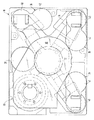
ラジアルアーム30がテレスコープ式チューブ26の上端に接続され、このアームの開放端上に中央柱32(下方に延びるガイド部材)が保持される。ガイドコラム32の下端は3個のアーム付きキャリア34にしっかりと固定される。キャリア34の3個の各アームの開放端には1個の線形駆動装置36が設置されており、各アームの開放端と線形駆動装置の下端は二軸カルダン継手38を介して接続されている。図3の平面図が示すように、キャリア34のアームは、3個の線形駆動装置36及びリフト用コラム20が長方形プレート型足部の4隅に配置されるように形成されている。
【0014】
各線形駆動装置に、スピンドル駆動装置及び低電圧電動モータ42を受容するテレスコープ式コラム40が公知の方法・構成で含まれる。この電動モータは上記リフト用コラム20と同じ方法で、チェーン駆動機構を通じてテレスコープ式柱40内部のスピンドルを駆動する。
【0015】
各テレスコープ式コラム40の上端は、二軸カルダン継手44を通じて支持コラム14のプレート形頭部46に接続されている。ロッド形ガイド要素50が、カルダン継手44の中間点で、さらにもう1つのカルダン継手48を通じて頭部46に接続されており、ガイド要素50は中空のガイドチューブ32内を回転はできないが垂直方向にスライドできるようにガイドされる。
【0016】
リフト用コラム及び3個の線形駆動装置から構成される支持コラム14の調節機構は、3個のカバーリング52によって囲まれ、これらのリングは望遠鏡の筒のように(テレスコープ式に)重なり合い互いにスライドし合って、頭部46の調節の如何にかかわらずコラムの内面空間を完全にカバーすることができる。頭部46はべローズ(bellows )を介して最上位のカバーリング52に接続される。
【0017】
上記から理解されるように、頭部46の高さは引上げコラム20を通じ調節される。線形駆動装置36により頭部46の傾きは所望の方向及び所望の軸に対して設定され得る。ガイド要素50が用いられることにより、線形駆動装置36により支持が可動的であるにもかかわらず、頭部46は回転せずに安定して保持される。
【0018】
本発明のリフト用コラムはその構成上非常にコンパクトであり、ゆえに直径が小さい。それにもかかわらずコラムを低くする、即ちコラム頭部及びコラム頭部上の患者支持手段を低くすることが、線形駆動装置が互いに障害となることなく可能なのである。このことは、線形駆動装置がその垂直位置から少しはコラム頭部46の傾きに応じて下がらねばならないので重要である。
【図面の簡単な説明】
【図1】本発明を具体化している手術台の概略斜視図である。
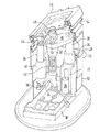
【図2】支持コラム内部及び調節機構内部の部分概略図である。
【図3】支持コラム足部の略平面図である。
【符号の説明】
10 患者支持手段
14 支持コラム
18 コラム足部
20 リフト用コラム
30,32,34 リフト用取付部材
36 線形駆動装置
46 コラム頭部
48 カルダン継手
50 ガイド要素[0001]
TECHNICAL FIELD OF THE INVENTION
The present invention relates to an improvement of a support column for holding a patient support means of an operating table. The support column has a foot and a head, the head being connected to the patient support means, the height of which can be adjusted with respect to the column foot by an adjustable mechanism in the support column, and a horizontal axis. Can turn around. The adjusting function includes a lifting column standing on the foot, the upper end of which is connected to a lifting mounting. The support column has a number of linear drives mounted parallel to the lift column, one end of each linear drive connected to the lift mount and the other end to the head by cardan joints (in cardan style). ing. The head and the mounting member for the lift (in addition to the above-mentioned joint) are connected via at least another cardan joint.
[0002]
Problems to be solved by the prior art and the invention
A support column of this kind is known, for example, from DE-A-22 60140. In this known configuration, the mounting member consists of a rectangular frame having two vertical sides and a lower and upper plate. The frame is guided in a rigid guide connected to the column foot so that its vertical sides can be adjusted up and down.
[0003]
The lower plate has two linear drives. The upper plate is connected to the head by a rigid rod and cardan joint. This type of support post is very space consuming. Also, because of the strong frame, the height of the head (and thus the patient support means) can only be lowered to relatively high positions.
[0004]
It is an object of the present invention to provide a support column of the known type, which takes up only a small amount of space (especially of small diameter), has a large adjustable area of the head, and in particular lowers the head and thus the patient support means. It is to provide a supporting column that can be lowered.
[0005]
[Means for Solving the Problems]
Means for solving the problems of the prior art according to the present invention are as follows. The lift column is rendered non-rotatable and the lift column and three linear drives are installed at or near the corner of the rectangle as shown in plan view. Also, the column head is connected to the guide element through another cardan joint located near the intersection of the rectangular diagonals, the guide element being vertically adjustable but non-rotatable on the lift mount. Guided.
[0006]
The solution according to the invention eliminates the need for a rigid frame and the large space required thereby. Despite the fact that the column requires only a small amount of space due to the above-described configuration of the linear drive, the freedom of rotation of the linear drive about its rotation axis is such that the column head is completely low (lowest position) Guaranteed even at certain times. Since a rigid frame is no longer used, the adjusted range of the linear drive can be used more efficiently, and thus the column head can be much lower than in conventional arrangements. Nevertheless, by using the guide element, the safety of the rotation of the column head relative to the column foot is ensured.
[0007]
The present invention provides an embodiment of a lift mounting member that saves a great deal of space and components. The lifting attachment has a hollow central column for receiving the guide element, which is connected at its upper end to the upper end of the lifting column through a radial arm and at its lower end to a carrier with three arms. A linear drive is hingedly connected to each arm of the carrier at a point near the open end of the arm.
[0008]
The lifting column and / or the linear drive can be formed in a known manner as an electromechanical spindle drive or a hydraulic (hydraulic, hydraulic) drive.
[0009]
To meet hygiene requirements (in the operating room) and protect the mechanisms in the support column from contamination, the adjustment mechanism is enclosed by a telescopic housing, which is connected at its upper end via a bellows to the column head. Have been.
[0010]
Other features and advantages of the present invention will become apparent from the following description, which illustrates the present invention by way of example with reference to the accompanying drawings.
[0011]
【Example】
The operating table shown in FIG. 1 includes a patient support means indicated by
[0012]
As shown in FIG. 2, the
[0013]
A
[0014]
Each linear drive includes a spindle drive and a
[0015]
The upper end of each
[0016]
The adjusting mechanism of the
[0017]
As can be seen from the above, the height of the
[0018]
The lift column of the present invention is very compact in construction and therefore has a small diameter. Nevertheless, it is possible to lower the column, ie the column head and the patient support means on the column head, without the linear drives interfering with each other. This is important because the linear drive must drop slightly from its vertical position in response to the tilt of the
[Brief description of the drawings]
FIG. 1 is a schematic perspective view of an operating table embodying the present invention.
FIG. 2 is a partial schematic view of the inside of a support column and the inside of an adjustment mechanism.
FIG. 3 is a schematic plan view of a support column foot.
[Explanation of symbols]
Claims (5)
前記調節機構が前記足部上に立脚するリフト用コラムを含み、前記リフト用コラムの上端がリフト用取付部材に接続され、前記リフト用取付部材が前記リフト用コラムに平行に設置される多数の線形駆動装置を有し、
前記線形駆動装置の各々がその一端で前記リフト用取付部材に他端で前記頭部に各々カルダン継手により接続され、前記頭部が少なくとももう1つのカルダン継手を通して前記リフト用取付部材に接続されている前記支持コラムにおいて、前記リフト用コラムが回転せず、前記リフト用コラム及び3個の線形駆動装置が上から見ると長方形の角もしくは少なくとも角近くに設置され、前記頭部が、前記長方形の対角線の交点近くに位置する上記もう1つのカルダン継手を通してガイド要素と接続され、前記ガイド要素が、リフト用取付部材上で調節可能がしかし回転不能にガイドされることを特徴とする支持コラム。A support column for holding a patient support means of an operating table, having a foot and a head, suitable for connection with the patient support means, and being high with respect to the foot by an adjustment mechanism inside the support column. Can be adjusted, rotated about a horizontal axis,
The adjusting mechanism includes a lift column standing on the foot, an upper end of the lift column is connected to a lift mounting member, and the lift mounting member is installed in parallel with the lift column. With a linear drive,
Each of the linear drives is connected at one end thereof to the lift mounting member by a cardan joint at the other end to the head, and the head is connected to the lift mounting member through at least another cardan joint; In the supporting column, the lifting column does not rotate, and the lifting column and three linear driving devices are installed at or near at least a corner of a rectangle when viewed from above, and the head has the rectangular shape. A support column connected to a guide element through said another cardan joint located near the intersection of diagonals, said guide element being adjustable but non-rotatably guided on a lifting attachment.
Applications Claiming Priority (2)
| Application Number | Priority Date | Filing Date | Title |
|---|---|---|---|
| DE4423402.3 | 1994-07-04 | ||
| DE4423402A DE4423402C2 (en) | 1994-07-04 | 1994-07-04 | Support column for holding a patient support surface |
Publications (2)
| Publication Number | Publication Date |
|---|---|
| JPH08182711A JPH08182711A (en) | 1996-07-16 |
| JP3549032B2 true JP3549032B2 (en) | 2004-08-04 |
Family
ID=6522214
Family Applications (1)
| Application Number | Title | Priority Date | Filing Date |
|---|---|---|---|
| JP16749995A Expired - Fee Related JP3549032B2 (en) | 1994-07-04 | 1995-07-03 | Support column holding patient support means |
Country Status (4)
| Country | Link |
|---|---|
| US (1) | US5528782A (en) |
| EP (1) | EP0691118B1 (en) |
| JP (1) | JP3549032B2 (en) |
| DE (2) | DE4423402C2 (en) |
Families Citing this family (79)
| Publication number | Priority date | Publication date | Assignee | Title |
|---|---|---|---|---|
| FR2739093B1 (en) * | 1995-09-21 | 1999-11-26 | Jurgen Michael Knapp | LIFTING COLUMN |
| US6484334B1 (en) | 1997-11-07 | 2002-11-26 | Hill-Rom Services, Inc. | Surgical table |
| EP1028686B1 (en) * | 1997-11-07 | 2004-03-10 | Hill-Rom Services, Inc. | Surgical table |
| US6101956A (en) * | 1997-12-16 | 2000-08-15 | Keil; Charles C. | Mobile veterinary treatment prep table |
| US8443761B2 (en) * | 1997-12-16 | 2013-05-21 | Midmark Corporation | Veterinary procedure table with scale |
| DE19756783C1 (en) * | 1997-12-19 | 1999-07-08 | Hans Pausch Roentgengeraetebau | Device for moving an X-ray table |
| DE19757313C1 (en) * | 1997-12-22 | 1999-09-09 | Niehaus | Device for height adjustment of plates |
| DE29815699U1 (en) * | 1998-09-01 | 1999-05-27 | Schmitz U Soehne Gmbh & Co Kg | Table, in particular operating table, with several hydraulically adjustable elements |
| AU5132200A (en) * | 1999-05-14 | 2000-12-05 | Arthur R. Stipan | Tiltable golf platform |
| US6269499B1 (en) * | 1999-06-29 | 2001-08-07 | General Electric Company | Multi-axis planar mechanism for a positioner patient platform |
| US6407770B1 (en) | 1999-08-19 | 2002-06-18 | General Electric Company | Apparatus and method for detecting defects in a discrete picture element detector circuit |
| WO2001034017A2 (en) * | 1999-11-12 | 2001-05-17 | Microdexterity Systems, Inc. | Manipulator |
| US6492802B1 (en) | 2000-07-14 | 2002-12-10 | Ge Medical Technology Services, Inc. | Apparatus and method for detecting defects in a multi-channel scan driver |
| US6640363B1 (en) * | 2000-10-16 | 2003-11-04 | Ge Medical Systems Global Technology Company, Llc | Mobile imaging table pivot mechanism |
| US6886200B2 (en) | 2001-01-25 | 2005-05-03 | Hill-Rom Services, Inc. | Hydraulic actuator apparatus for a surgical table |
| DE10114702C1 (en) * | 2001-03-23 | 2002-10-31 | Dornier Medtech Holding Int Gmbh | Height adjustable patient support has tilting moment received by support parallel to lifting axis |
| US6505364B2 (en) * | 2001-03-27 | 2003-01-14 | Ge Medical Systems Global Technology Company, Llc | Method and apparatus for covering an adjustable patient table |
| US6814409B2 (en) * | 2001-04-12 | 2004-11-09 | A-Dec, Inc. | Hydraulic drive system |
| US6568008B2 (en) | 2001-06-19 | 2003-05-27 | The Brewer Company, Llc | Medical examination table with two-way drawers and articulating backrest |
| US6550084B2 (en) | 2001-06-19 | 2003-04-22 | The Brewer Company, Llc | Medical examination table step |
| GB0119132D0 (en) * | 2001-08-03 | 2001-09-26 | Seminar Components Uk Ltd | Imrovements in and relating to adjustable chairs and beds |
| GB0124126D0 (en) * | 2001-10-08 | 2001-11-28 | Eschmann Holdings Ltd | Surgical tables |
| US6721976B2 (en) | 2002-02-05 | 2004-04-20 | Reliance Medical Products, Inc. | Surgical table |
| US7073222B1 (en) * | 2003-05-06 | 2006-07-11 | Skripps Thomas K | Medical procedure table |
| US6983499B2 (en) * | 2003-05-21 | 2006-01-10 | Dreamwell, Ltd. | Adjustable bed shields |
| JP3780267B2 (en) | 2003-08-08 | 2006-05-31 | 株式会社日立製作所 | Radiotherapy bed equipment |
| USD496462S1 (en) | 2003-09-29 | 2004-09-21 | The Brewer Company, Llc | Medical examination table |
| US20090044762A1 (en) * | 2007-08-14 | 2009-02-19 | Midmark Corporation | Grille for veterinary procedure tables |
| DE102004013585B4 (en) * | 2004-03-19 | 2007-04-19 | Straßer, Wilhelm Friedrich, Dipl.-Ing. | Transport and storage system for patients in the clinical area |
| US20060258932A1 (en) * | 2005-05-10 | 2006-11-16 | General Electric Company | Safe motion enabling sequence and system for a medical imaging apparatus |
| US7513000B2 (en) | 2005-07-28 | 2009-04-07 | The Brewer Company, Llc | Medical examination table |
| US9038216B2 (en) | 2005-07-28 | 2015-05-26 | The Brewer Company, Llc | Medical examination table |
| US9119610B2 (en) * | 2005-08-10 | 2015-09-01 | Joel M. Matta | Medical table having controlled movement and method of use |
| DE102005056275C5 (en) † | 2005-11-14 | 2012-06-28 | Trumpf Medizin Systeme Gmbh | Operating table with a patient support plate |
| US7530542B2 (en) * | 2006-12-07 | 2009-05-12 | Deere & Company | Locking mounting assembly |
| WO2009000939A1 (en) * | 2007-06-22 | 2008-12-31 | Gmv, S.A. | Laparoscopic surgical simulator |
| DE502007007063D1 (en) * | 2007-08-03 | 2011-06-09 | Trumpf Medizin Systeme Gmbh & Co Kg | operating table |
| DE102007043431A1 (en) * | 2007-09-12 | 2009-03-19 | Maquet Gmbh & Co. Kg | Transport trolley for the patient support surface of a surgical table |
| US9192457B2 (en) * | 2008-04-14 | 2015-11-24 | Midmark Corporation | Veterinary procedure table |
| DE202008008574U1 (en) * | 2008-06-25 | 2008-08-28 | Maquet Gmbh & Co. Kg | Covering a height-adjustable support column |
| US8635725B2 (en) * | 2008-10-28 | 2014-01-28 | Tony Y. Tannoury | Prone and laterally angled surgical device and method |
| US8763178B1 (en) * | 2009-08-19 | 2014-07-01 | Martin Manufacturing Co., Llc | Low profile patient examination table |
| DE102009047869B4 (en) | 2009-09-30 | 2014-06-05 | Maquet Gmbh & Co. Kg | Adapter for connecting at least one accessory to an operating table and system comprising an operating table, at least one accessory and an adapter |
| DE102011000628A1 (en) | 2011-02-10 | 2012-08-16 | Maquet Gmbh & Co. Kg | Operating table column |
| US9220359B2 (en) * | 2012-02-07 | 2015-12-29 | Raymond Long | Exercise mat |
| US9119755B2 (en) * | 2012-09-07 | 2015-09-01 | Medcare Products, Inc. | Low profile rolling support assembly |
| USD745971S1 (en) * | 2013-03-06 | 2015-12-22 | Operating Room Safety Enterprises, LLC | Surgical table |
| CN103431971A (en) * | 2013-08-21 | 2013-12-11 | 仙居药城医疗器械有限公司 | Electric operation table |
| DE102013223486A1 (en) * | 2013-11-18 | 2015-05-21 | Berchtold Holding AG | operating table |
| DE102014104681B4 (en) * | 2014-04-02 | 2018-02-08 | MAQUET GmbH | Operating table column and operating table with such an operating table column |
| DE102014109375A1 (en) | 2014-07-04 | 2016-01-07 | MAQUET GmbH | Operating table column for an operating table |
| DE102014109376B4 (en) | 2014-07-04 | 2017-11-09 | MAQUET GmbH | Operating table base for an operating table |
| DE102014109377B4 (en) | 2014-07-04 | 2017-11-16 | MAQUET GmbH | Device for height adjustment of an operating table and operating table with such a device |
| CN105476798A (en) * | 2015-10-09 | 2016-04-13 | 常州好利医疗器械有限公司 | Operating adjusting table with waist adjusting function |
| WO2017123731A1 (en) * | 2016-01-12 | 2017-07-20 | Virginia Commonwealth University | Systems, devices, and methods for position monitoring and motion compensation |
| MX2018011935A (en) | 2016-04-01 | 2019-01-15 | Utopix Medical Llc | Tilt-tip moldable total care bed. |
| CN106236486A (en) * | 2016-08-26 | 2016-12-21 | 无锡怡生医疗设备有限公司 | A kind of operating table lifting upright post |
| CN106236487A (en) * | 2016-08-26 | 2016-12-21 | 无锡怡生医疗设备有限公司 | A kind of operation table big bearing base support means |
| USD865971S1 (en) | 2016-08-29 | 2019-11-05 | Siemens Healthcare Gmbh | Patient table |
| USD855189S1 (en) * | 2016-08-30 | 2019-07-30 | Siemens Healthcare Gmbh | Patient table |
| CN208114761U (en) * | 2016-11-11 | 2018-11-20 | 通快医疗系统两合公司 | Sealing device for operating table |
| EP3518854A4 (en) | 2016-11-28 | 2020-09-02 | Verb Surgical Inc. | Robotic surgical system to reduce unwanted vibration |
| DE102016125800A1 (en) * | 2016-12-28 | 2018-06-28 | MAQUET GmbH | Operating table column with stabilization guide |
| US10206841B2 (en) * | 2017-01-06 | 2019-02-19 | Aktiebolaget Skf | Actuation system for controlling the movement of a table |
| US10952913B2 (en) | 2017-04-28 | 2021-03-23 | Trumpf Medizin Systeme Gmbh + Co. Kg | Cladding protection units for telescoping columns and adjustable support apparatuses |
| US10945905B2 (en) * | 2017-05-31 | 2021-03-16 | Mizuho Osi | System, apparatus and method for supporting and/or positioning a patient before, during, or after a medical procedure |
| GB2566078B (en) * | 2017-09-04 | 2020-07-01 | Eschmann Holdings Ltd | Surgical tables |
| GB2566080B (en) * | 2017-09-04 | 2020-06-24 | Eschmann Holdings Ltd | Surgical tables |
| GB2566129B (en) * | 2017-09-04 | 2020-07-01 | Eschmann Holdings Ltd | Surgical tables |
| US10610435B2 (en) * | 2017-09-15 | 2020-04-07 | Robert Dan Allen | Surgical table cladding protective device |
| GB2567657B (en) * | 2017-10-18 | 2019-10-23 | Eschmann Holdings Ltd | Surgical tables |
| USD954964S1 (en) * | 2018-07-27 | 2022-06-14 | United Metal Fabricators, Inc. | Medical examination table |
| DE102018124135A1 (en) * | 2018-09-28 | 2020-04-02 | MAQUET GmbH | Table column for an operating table with stiffening mechanism for a cylindrical guide |
| EP3659569B1 (en) * | 2018-11-29 | 2021-09-01 | TRUMPF Medizin Systeme GmbH + Co. KG | Operating table and method for operating the operating table |
| JP2022525037A (en) | 2019-03-08 | 2022-05-11 | オーリス ヘルス インコーポレイテッド | Tilt mechanism and applications for medical systems |
| TWI684439B (en) * | 2019-04-24 | 2020-02-11 | 明基三豐醫療器材股份有限公司 | Working bench column |
| IT202000003641A1 (en) * | 2020-02-21 | 2021-08-21 | Costr Strumenti Oftalmici C S O S R L | UNIT ARMCHAIR, IN PARTICULAR BUT NOT EXCLUSIVELY AN OPHTHALMIC UNIT |
| US11957627B2 (en) | 2020-10-09 | 2024-04-16 | Robert Dan Allen | Surgical table cladding protective device |
| DE102021100312A1 (en) * | 2021-01-11 | 2022-07-14 | Ewellix AB | Device for leveling a platform and system and patient tray |
Family Cites Families (7)
| Publication number | Priority date | Publication date | Assignee | Title |
|---|---|---|---|---|
| GB910029A (en) * | 1960-05-06 | 1962-11-07 | Central Design Office Of The M | Universal operating table with automatic control |
| US3176975A (en) * | 1960-09-19 | 1965-04-06 | Ritter Co Inc | Surgical table |
| US3206188A (en) * | 1961-08-28 | 1965-09-14 | Shampaine Ind Inc | Hydraulically actuated surgical operating tables |
| DE2260140A1 (en) * | 1972-12-08 | 1974-06-12 | Stille Werner Ab | OPERATING TABLE |
| US3940771A (en) * | 1975-04-21 | 1976-02-24 | Rockwell International Corporation | Variable angle support apparatus |
| SU1216141A1 (en) * | 1983-09-12 | 1986-03-07 | Харьковский Тракторный Завод Им.Серго Орджоникидзе | Hoisting apparatus |
| US5340111A (en) * | 1993-06-10 | 1994-08-23 | Froelich David S | Golf driving range platform |
-
1994
- 1994-07-04 DE DE4423402A patent/DE4423402C2/en not_active Expired - Fee Related
-
1995
- 1995-06-28 US US08/495,939 patent/US5528782A/en not_active Expired - Lifetime
- 1995-07-03 EP EP95110360A patent/EP0691118B1/en not_active Expired - Lifetime
- 1995-07-03 DE DE59507125T patent/DE59507125D1/en not_active Expired - Lifetime
- 1995-07-03 JP JP16749995A patent/JP3549032B2/en not_active Expired - Fee Related
Also Published As
| Publication number | Publication date |
|---|---|
| DE4423402A1 (en) | 1996-01-11 |
| EP0691118B1 (en) | 1999-10-27 |
| EP0691118A2 (en) | 1996-01-10 |
| JPH08182711A (en) | 1996-07-16 |
| DE4423402C2 (en) | 1999-12-30 |
| DE59507125D1 (en) | 1999-12-02 |
| EP0691118A3 (en) | 1996-04-03 |
| US5528782A (en) | 1996-06-25 |
Similar Documents
| Publication | Publication Date | Title |
|---|---|---|
| JP3549032B2 (en) | Support column holding patient support means | |
| JP5236734B2 (en) | Lift columns for treatment tables, hospital beds, and care beds | |
| US5339750A (en) | Adjustable work table | |
| US4087872A (en) | Movable bed frame | |
| JP2006326307A (en) | Lift bed | |
| JPH02198555A (en) | Positioning device for mattress of baby-incubator | |
| US6505364B2 (en) | Method and apparatus for covering an adjustable patient table | |
| JPH05269145A (en) | Three dimensional position adjustable ceiling suspension device for microscope | |
| JP2011017738A (en) | Display support device | |
| DE59509041D1 (en) | Table with movable top | |
| US4757968A (en) | Apparatus for implementation of vertical movement of a chair, especially of a patient chair | |
| US4570547A (en) | Table with adjustable height mechanism | |
| JPH0675409U (en) | Mobile X-ray diagnostic device | |
| CN216619398U (en) | Portable oral illuminating lamp for stomatology | |
| KR19980082935A (en) | Stand for beam projector | |
| JP3736890B2 (en) | Floor lifting device | |
| JP2657738B2 (en) | Mounting device for horizontal members | |
| JP2989323B2 (en) | Spot welding equipment | |
| JP2785864B2 (en) | Side fence with support height adjustment mechanism | |
| JPS6340987Y2 (en) | ||
| CN110169771B (en) | Tiltable magnetic resonance apparatus | |
| KR102592570B1 (en) | Automatic height-adjustable desk | |
| CN220186260U (en) | Supporting device of X-ray detector | |
| KR200338354Y1 (en) | A monitor stand using magnetism with adjust function of ups and downs and angle | |
| KR200277569Y1 (en) | ascending/descending and folding structure for running exerciser |
Legal Events
| Date | Code | Title | Description |
|---|---|---|---|
| TRDD | Decision of grant or rejection written | ||
| A01 | Written decision to grant a patent or to grant a registration (utility model) |
Free format text: JAPANESE INTERMEDIATE CODE: A01 Effective date: 20040316 |
|
| A61 | First payment of annual fees (during grant procedure) |
Free format text: JAPANESE INTERMEDIATE CODE: A61 Effective date: 20040414 |
|
| R150 | Certificate of patent or registration of utility model |
Free format text: JAPANESE INTERMEDIATE CODE: R150 |
|
| R250 | Receipt of annual fees |
Free format text: JAPANESE INTERMEDIATE CODE: R250 |
|
| FPAY | Renewal fee payment (event date is renewal date of database) |
Free format text: PAYMENT UNTIL: 20090430 Year of fee payment: 5 |
|
| FPAY | Renewal fee payment (event date is renewal date of database) |
Free format text: PAYMENT UNTIL: 20100430 Year of fee payment: 6 |
|
| FPAY | Renewal fee payment (event date is renewal date of database) |
Free format text: PAYMENT UNTIL: 20110430 Year of fee payment: 7 |
|
| FPAY | Renewal fee payment (event date is renewal date of database) |
Free format text: PAYMENT UNTIL: 20110430 Year of fee payment: 7 |
|
| FPAY | Renewal fee payment (event date is renewal date of database) |
Free format text: PAYMENT UNTIL: 20120430 Year of fee payment: 8 |
|
| FPAY | Renewal fee payment (event date is renewal date of database) |
Free format text: PAYMENT UNTIL: 20120430 Year of fee payment: 8 |
|
| FPAY | Renewal fee payment (event date is renewal date of database) |
Free format text: PAYMENT UNTIL: 20130430 Year of fee payment: 9 |
|
| FPAY | Renewal fee payment (event date is renewal date of database) |
Free format text: PAYMENT UNTIL: 20140430 Year of fee payment: 10 |
|
| R250 | Receipt of annual fees |
Free format text: JAPANESE INTERMEDIATE CODE: R250 |
|
| LAPS | Cancellation because of no payment of annual fees |