JP3547987B2 - Water heater - Google Patents
Water heater Download PDFInfo
- Publication number
- JP3547987B2 JP3547987B2 JP08433698A JP8433698A JP3547987B2 JP 3547987 B2 JP3547987 B2 JP 3547987B2 JP 08433698 A JP08433698 A JP 08433698A JP 8433698 A JP8433698 A JP 8433698A JP 3547987 B2 JP3547987 B2 JP 3547987B2
- Authority
- JP
- Japan
- Prior art keywords
- tapping
- hot water
- water
- energy saving
- water heater
- Prior art date
- Legal status (The legal status is an assumption and is not a legal conclusion. Google has not performed a legal analysis and makes no representation as to the accuracy of the status listed.)
- Expired - Fee Related
Links
Images


Landscapes
- Heat-Pump Type And Storage Water Heaters (AREA)
Description
【0001】
【発明の属する技術分野】
本発明は、給湯機に関し、詳しくは、省エネルギ運転が可能な給湯機に関するものである。
【0002】
【従来の技術】
近年の給湯機は出湯先が多岐にわたっており、例えば、台所や洗面所や浴室などに設けられた各水栓、あるいは、シャワー装置などへも一つの給湯機で給湯可能となっている。
【0003】
他方、各地で水不足が発生するにつれて節水への関心が高まり、給湯機にも節水機能を付加したものが開発されている。
【0004】
例えばこの種の給湯機には、特開平9−303865号に示すものがあり、これは、制限流量最大値を同最大値よりも低い所定流量値に制限する流量制限手段を具備し、給湯機の能力を強制的に低く抑えることによって、使用者が水栓で流量を絞ることなく節水することができるようにしている。また、制限流量の設定や解除は、使用者が操作部により任意に操作可能としている。
【0005】
【発明が解決しようとする課題】
ところが、上記した従来の給湯機には、未だ下記に示すような課題が残されていた。
【0006】
すなわち、台所で食器洗いに湯を使用する場合と、浴室でシャワーを使用する場合とでは制限流量が異なるために、その都度適正な制限流量に変更する必要があり不便であった。
【0007】
また、近年では節水のみに止まらず、トータル的な省エネルギ化が要求されており、湯の設定温度に何ら制限を設けていない上記従来の技術では燃料消費量の改善ができないので大きな省エネルギ化は図れないものであった。
【0008】
本発明は、上記課題を解決することのできる給湯機を提供することを目的としている。
【0009】
【課題を解決するための手段】
そこで、請求項1記載の本発明では、用途の異なる複数の出湯先にそれぞれ出湯要求の有無を検出する検出手段を設け、出湯要求のあった出湯先に応じて最大出湯量を変更するように制御した。
【0010】
また、請求項2記載の本発明では、用途の異なる複数の出湯先にそれぞれ遠隔操作盤を設け、同遠隔操作盤に、省エネルギ運転スイッチを設けた給湯機において、流量制限機能を有し、省エネルギ運転スイッチのON操作に応じて、同スイッチを具備する遠隔操作盤を設けた出湯先に見合った最大出湯量に変更することとした。
【0012】
また、請求項3記載の本発明では、最大出湯量の設定を遠隔操作盤で行えるようにした。
【0013】
また、請求項4記載の本発明では、流量制限機能の解除は、出湯先に拘束されることなくいずれの遠隔操作盤からも行えるようにした。
【0014】
また、請求項5記載の本発明では、省エネルギ運転スイッチがONされると、出湯目標温度を設定温度よりも一定温度低くすることとした。
【0015】
また、請求項6記載の本発明では、遠隔操作盤に、省エネルギ運転スイッチがONされていることを報知する報知手段を設けた。
【0016】
さらに、請求項7記載の本発明では、用途の異なる複数の出湯先が台所の水栓と、シャワー装置とであることとした。
【0017】
【発明の実施の形態】
本発明に係る給湯機は、用途の異なる複数の出湯先にそれぞれ出湯要求の有無を検出する検出手段を設け、出湯要求のあった出湯先に応じて最大出湯量を変更するように制御したものである。
【0018】
用途の異なる複数の出湯先としては、台所の水栓と、浴室のシャワー装置とであることとし、台所で食器等を洗う場合の出湯量と、浴室でシャワーを使用する場合とで最大出湯量をそれぞれに見合うように変更している。
【0019】
また、上記異なる出湯先である台所と浴室にそれぞれ遠隔操作盤(以下、台所リモコンと浴室リモコンという)を設け、両リモコンに、省エネルギ運転スイッチ(以下省エネスイッチという)をそれぞれ設けて、使用者が通常運転と省エネ運転とを選択して使用できるようにしている。
【0020】
さらに、本実施の形態では給湯機に流量制限機能をもたせ、省エネスイッチのON操作に応じて、同スイッチを具備するリモコンを設けた出湯先の用途に見合う最大出湯量、すなわち台所リモコンであれば食器洗いに見合う最大出湯量、浴室リモコンであればシャワー使用に見合う最大出湯量に変更するように制御している。例えば、食器洗いであれば適正流量は5リットル/分であり、シャワーであれば適正流量は10リットル/分なので、それぞれに応じた最大出湯量に強制的に変更することで大きな節水効果を得ることができる。
【0021】
しかも、かかる各出湯先における最大出湯量の設定を台所で使用するのであれば台所リモコンで、シャワー装置を使用するのであれば浴室リモコンで行えるようにすることができ、使用者に湯量不足で不自由な思いをさせることがないようにしている。
【0022】
また、前記流量制限機能の解除は、出湯先に拘束されることなくいずれのリモコンからも行えるようにすることができる。すなわち、台所リモコンからでも浴室リモコンで設定したシャワー用の最大出湯量を、浴室リモコンからでも台所リモコンで設定した食器洗い用の最大出湯量をキャンセルできるようにし、使い勝手をより向上させることができる。
【0023】
また、省エネスイッチがONされると、出湯目標温度を設定温度よりも一定温度低くすることもできる。
【0024】
このように、出湯先に応じて温度を強制的に設定温度よりも一定温度だけ低くすることでガスや灯油等の燃料消費量を低減させることができ、大きな省エネ効果が得られる。
【0025】
ところで、前記各リモコンには、省エネスイッチがONされていることを報知する報知手段を設けることが好ましい。すなわち、使用者が給湯機の現在の運転状態をいつでも確認できるようにしておけば、使用目的によって通常運転から省エネ運転へ、あるいは省エネ運転から通常運転へといつでも切換え可能にするためである。
【0026】
このように、本発明に係る給湯機は、用途の異なる複数の出湯先で各出湯先の湯の用途に見合った適正な最大出湯量に制限でき、湯量に大きな不満を抱くことなく自然に節水効果を得ることができる。
【0027】
また、出湯先に設けたリモコンによって運転状況が確認できるとともに、それぞれのリモコンで省エネ運転の開始が行え、また、その解除はいずれのリモコンでも行えるので使い勝手がきわめて良好である。
【0028】
【実施例】
以下、本発明の実施例について図面を参照しながら説明する。
【0029】
(第1実施例)
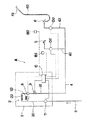
図1は第1実施例に係る給湯機Aの模式的説明図である。図示するように、給湯機Aは、互いに連通連結した入水管20と出湯管21と吸熱管22とを具備する熱交換器2をケーシング1内に配設し、前記入水管20と外部からの給水管3とを連通連結するとともに、出湯管21と給湯管4とを連通連結している。23はバーナである。
【0030】
給湯管4は中途で分岐して複数の出湯先に伸延しており、本実施例では、一方の分岐流路41を台所に設けた台所用水栓5に連通連結するとともに、他方の分岐流路42を浴室に設けた浴室用水栓6に連通連結している。また、浴室用水栓6には連結管60を介してシャワーヘッド61を接続してシャワー装置を構成している。
【0031】
また、前記入水管20の中途には水量センサ7を取付け、出湯管21の中途には、上流側からサーミスタからなる出湯温度センサ8と、出湯量を制御する流量調整バルブ9を配設している。
【0032】
給湯機Aは、遠隔操作盤(リモコン)により操作可能となっており、台所には台所用リモコンB1を、浴室には浴室用リモコンB2を配設して、電源のON・OFFや出湯温度の温度設定を行えるようにしている。
【0033】
かかるリモコンB1,B2 は、前記した水量センサ7、出湯温度センサ8、流量調整バルブ9とともに、ケーシング1内に配設された制御部Cに電気的に接続している。
【0034】
上記構成において、本実施例の特徴をなすのは、台所用水栓5と浴室用水栓6にそれぞれ出湯要求の有無を検出する出湯検出手段D1,D2 を設け、出湯要求のあった出湯先に応じて最大出湯量を変更するように制御したことにある。
【0035】
すなわち、前記制御部Cに流量制限機能をもたせ、図1に示すように、台所用水栓5及び浴室用水栓6に、それぞれ例えば水流スイッチなどからなる出湯検出手段D1,D2 を設け、これらを前記制御部Cと接続して、水栓5,6 が操作されて出湯が検出されると、水量センサ7で検出した給湯機Aへの入水量に基づき、流量調整バルブ9の開閉量を調整して台所で食器等を洗う場合の第1の流量と、浴室でシャワーを使用する場合の第2の流量とで最大出湯量をそれぞれに見合うように変更するものである。
【0036】
本実施例では、第1の流量となる台所用水栓5の最大出湯量を5リットル/分に、第2の流量となる浴室用水栓6の最大出湯量を10リットル/分に制限するようにしている。かかる数値は、通常使用する場合の適正流量であり、経験的に割り出されている。
【0037】
したがって、各水栓5,6 からの最大出湯量は、それぞれの用途に見合った流量値に制限されるので、使用者は意識することなく節水することができる。
【0038】
また、前記リモコンB1,B2 に省エネルギ運転スイッチ(以下省エネスイッチという)12を設け(図4参照)、同スイッチ12がONされたときに台所で食器等を洗う場合の出湯量と、浴室でシャワーを使用する場合とで最大出湯量をそれぞれに見合うように変更することもできる。
【0039】
さらに、省エネ運転とした場合、すなわち、省エネスイッチ12がONの場合は、要求出湯温度よりも一定温度低い出湯温度に強制的に変更することもできる。
【0040】
すなわち、省エネスイッチ12がONの場合は、節水を含めて大幅な省エネ効果を生起できるように、設定された出湯温度よりも実際には一定値低い温度で出湯するようにして、ガスや灯油等の消費量を節約するものである。
【0041】
例えば、シャワーを使用している際に、設定温度を40℃として表示画面15にはそのように表示されていても、省エネスイッチ12をONにした場合は、実際の出湯温度は38℃あるいは39℃しにするものである。かかる構成により、省エネ効果をより高めることができる。
【0042】
すなわち、かかる制御をフローチャートで示すと図2のようになる。
【0043】
省エネスイッチ12がONされない場合は通常運転として最大出湯量を20リットル/分に設定し(STEP 1)、ONされている場合、台所で使用されている場合は第1の流量である5リットル/分に制限し(STEP 2)、浴室で使用されている場合は第2の流量である10リットル/分に制限する(STEP 3)。
【0044】
そして、流量を制限するとともに、いずれの水栓5,6 からの出湯であっても、実際の出湯温度を一定温度低く設定されたものとして温度管理をするものである(STEP 4),(STEP 5) 。なおこの場合、台所用水栓5からの出湯温度のみを一定温度低くするようにしてもよい。
【0045】
なお、本実施例の変形例として、図3に示すように、出湯検出手段D1,D2 を給湯機Aのケーシング1内に設けることもできる。
【0046】
すなわち、ケーシング1内において、出湯管21を分岐流路41a,42a に分岐させるとともに、各分岐流路41a,42a と台所用給湯管43と浴室用給湯管44とを連通連結し、前記各分岐流路41a,42a の中途に出湯検出手段D1,D2 を設けている。
【0047】
この場合、制御部Cと出湯検出手段D1,D2 とを接続する電気信号線はケーシング1の内部配線で済み、また、出湯検出手段D1,D2 を各水栓5,6 に取付ける必要がないので給湯機Aの設置工事が容易となる。なお、他の構成は図1に示したものと同様である。
【0048】
なお、本実施例では、台所及び浴室とで同時に出湯する場合においては、浴室用水栓6を優先して最大出湯量を設定するようにしている。もともと適正流量の少ない台所用水栓5を優先すると、シャワーを使用する場合に出湯量が不足してしまうからである。また、台所及び浴室の最大出湯量の合計を15リットル/分としてもよい。
【0049】
(第2実施例)
次に、第2実施例に係る給湯機Aについて説明する。これは、第1実施例で説明した節水運転を、前記した台所用・浴室用リモコンB1,B2 による操作で行えるようにしたものである。
【0050】
すなわち、流量制限などを行わない通常運転とするか、省エネ運転とするかを使用者がリモコン操作で選択的に行えるようにしている。
【0051】
さらに、本実施例でも、第1実施例同様に、省エネ運転とした場合、すなわち省エネスイッチ12がONの場合は、要求出湯温度よりも一定温度低い出湯温度に強制的に変更することもできる。
【0052】
例えば、シャワーを使用している際に、設定温度を40℃として表示画面15にはそのように表示されていても、省エネスイッチ12をONにした場合は、実際の出湯温度は39℃あるいは38℃にするものである。かかる構成により、省エネ効果をより高めることができる。
【0053】
図4に本実施例に係る台所用・浴室用リモコンB1,B2 の概略を示している。なお、台所用・浴室用リモコンB1,B2 を主と副とに分け(通常は台所用リモコンB1を主とする)、その大きさや形状、また、備えるスイッチ類の数等を異ならせてもよいが、本実施例では便宜的に同一仕様としたもので説明する。
【0054】
図示するように、リモコンB1,B2 には、給湯機Aを立ち上げる運転スイッチ11と省エネスイッチ12とを設けており、省エネスイッチ12の操作により、前述したように、出湯要求のあった出湯先に応じて最大出湯量を変更できるようにしている。
【0055】
すなわち、かかる制御をフローチャートで示すと、図5に示すように、省エネスイッチ12がONされていない場合は、通常運転として最大出湯量を20リットル/分に設定し(STEP 1)、ONされている場合、これが台所用リモコンB1によるON操作であるならば、5リットル/分に制限し(STEP 2)、浴室リモコンB2で省エネスイッチ12をONしたのであればシャワー使用に見合う10リットル/分に最大出湯量を制限するように変更するもので(STEP 3) 、変更された最大流量値はリモコンB1,B2 に設けた液晶表示による表示画面15に表示される。
【0056】
そして、このように最大出湯量を制限した後は、いずれの水栓5,6 からの出湯であっても、実際の出湯温度を一定温度低く設定されたものとして温度管理をして出湯するようにしている(STEP 4),(STEP 5) 。なおこの場合、台所用水栓5からの出湯温度のみを一定温度低くするようにしてもよい。
【0057】
また、図4に示すように、台所用・浴室用リモコンB1,B2 には報知手段としての表示ランプ11a,12a を設けており、給湯機Aが立上状態の場合は、表示ランプ11a が点灯し、省エネスイッチ12がONの場合は表示ランプ12a が点灯する。したがって、使用者は給湯機Aの運転状態をリモコンB1,B2 を見るだけで容易に把握することができる。
【0058】
また、リモコンB1,B2 には流量・温度変更スイッチ13,14 を設けており、前記した最大出湯量の設定をリモコンB1,B2 で行えるようにしている。なお、流量・温度変更スイッチ13はUP側へ、流量・温度変更スイッチ14はDOWN側への変更を行う。
【0059】
本実施例では、以下の要領で最大出湯量の設定を行うようにしている。
【0060】
省エネスイッチ12をONすると、表示画面15に表示された流量値が所定時間(例えば10秒間)点滅し、この時間内に前記流量・温度変更スイッチ13,14 を操作し、最大出湯量を所望する制限流量に設定する。なお、この流量変更用に設定された所定時間が経過した後は、流量・温度変更スイッチ13,14 は温度変更用のスイッチとして機能し、前記同じ要領で所望する出湯温度に設定することができる。なお、この設定した出湯温度は、設定した最大出湯量とともに、表示画面15に表示される(図4参照)。
【0061】
このように、本実施例によれば、節水と湯量の満足感との兼ね合いを使用者で決定することができる。
【0062】
ところで、省エネスイッチ12のOFFは、いずれのリモコンB1,B2 からでも操作可能としている。
【0063】
例えば、台所用リモコンB1で省エネスイッチ12をONし、最大流量が5リットル/分に制限されている場合、シャワーを使用しようとした場合には流量が少なすぎるので、浴室用リモコンB2で省エネスイッチ12をOFFすることが可能である。また、OFFした後に改めてシャワーの使用で節水しようとすれば、浴室用リモコンB2で省エネスイッチ12をONすれば、最大流量は10リットル/分に変更される。
【0064】
さらに、この設定量を、例えば11リットル/分等に適宜変更することも可能である。また、当然ながら、浴室用リモコンB2で設定したものを台所用リモコンB1にてキャンセルしたりすることも可能である。
【0065】
このように、本実施例では、台所や浴室に設けたリモコンB1,B2 によって運転状況が確認できるとともに、それぞれのリモコンB1,B2 で省エネ運転の開始が行え、また、その解除もいずれのリモコンB1,B2 からでも行えるので使い勝手がきわめて良好となる。
【0066】
また、本実施例及び第1実施例では、節水用に出湯先に応じて最大出湯量を変更可能とし、これ以上の流量要求があっても、制限された最大出湯量で規制して節水効果を狙ったものとしているが、省エネスイッチ12がONされた場合は、最大出湯量以下の要求水量であっても、実際の出湯量を一定量減じるようにすることもできる。
【0067】
例えば、台所で食器洗いをしている場合、水栓5のバルブ開度が4リットル/分の流量であれば、実際には3.5 リットル/分で出湯するように制御するものである。かかる構成とすれば、より確実な節水効果をあげることができる。
【0068】
また、本実施例において、台所及び浴室とで同時に省エネ運転で出湯する場合には、先の第1実施例同様に、最大流量の大きい浴室用水栓6の方を優先して最大流量が設定されるように制御している。
【0069】
(第3実施例)
次に、図6及び図7に示す第3実施例にかかる給湯機Aについて説明する。
【0070】
これは、先の第1、第2実施例においては、分岐流路41,42,41a,41b に分岐する前の出湯管21に流量制限バルブ9を設けていたが、かかる構成では、一方の出湯先の制限最大出湯量に規定されるために、他方では確実な節水が行えない場合がある。そこで、各出湯先で独立して省エネ運転が可能としたものである。
【0071】
そのために、図6に示すように、出湯管21の下流側から分岐して台所用水栓5、浴室用水栓6に連通する分岐流路41a,41b に出湯温度センサ8a,8b 、流量調整バルブ9a,9b を配設し、台所用水栓5及び浴室用水栓6の各出湯検出手段D1,D2 が出湯を検出すると、それぞれの分岐流路41a,41b に設けた流量調整バルブ9a, 9bを独立して開弁制御するようにしている。
【0072】
かかる構成とすることにより、台所用水栓5と浴室用水栓6が同時に省エネ運転で出湯する場合、台所用水栓5では最大出湯量が5リットル/分に、浴室用水栓6では最大流量が10リットル/分でそれぞれ規制されることになり、使用者はいずれの水栓5(6)からも他側の水栓6(5)の状態を気にすることなく使用している水栓5,6 に見合った適正な制限最大出湯量で湯を使用できるので使い勝手がよく、かつ、確実に節水効果を奏することができる。
【0073】
なお、この場合でも、各リモコンB1,B2 の操作で最大出湯量の設定を行えるとともに、省エネ運転の解除は、出湯先に拘束されることなくいずれのリモコンB1,B2 からも行え、さらに、省エネスイッチ12がONされると、出湯目標温度を設定温度よりも一定温度低くするような省エネ運転も行える。
【0074】
また、第1実施例の変形例で説明したように、本実施例においても、出湯検出手段D1,D2 を図7に示すようにケーシング1内に収納配設することもできる。
【0075】
以上、各実施例を通して本発明を説明したが、本発明は各実施例に限定されるものではなく、特許請求の範囲に記載された範囲での変更は自由である。
【0076】
また、各実施例で最大出湯量と表したのは、必ずしも入水した水を熱交換器2で加熱したものに限るものではなく、水の出水も含むものである。すなわち、温度設定を水の温度と変わらないように設定した場合は、熱交換機2は作動しなくても、給湯機Aが立ち上がっているのであれば制御部Cは作動して流量制御を行う。また、省エネスイッチ12を運転スイッチ11のON/OFFと独立させることで、熱交換器2を作動させずに省エネスイッチ12をON/OFFできるようにしてもよい。
【0077】
【発明の効果】
本発明は、以上説明したような形態で実施され、以下に記載されるような効果を奏する。
【0078】
請求項1記載の本発明では、用途の異なる複数の出湯先にそれぞれ出湯要求の有無を検出する検出手段を設け、出湯要求のあった出湯先に応じて最大出湯量を変更するように制御したことにより、使用者は意識することなく節水することができる。
【0079】
請求項2記載の本発明では、用途の異なる複数の出湯先にそれぞれ遠隔操作盤を設け、同遠隔操作盤に、省エネルギ運転スイッチを設けたので、使用者が省エネ運転、通常運転のいずれかを自由に選択することができる。
また、流量制限機能を有し、省エネルギ運転スイッチのON操作に応じて、同スイッチを具備する遠隔操作盤を設けた出湯先に見合った最大出湯量に変更することとしたので、使用する場所で即座に省エネ運転による出湯が可能となり使い勝手が向上する。
【0080】
請求項3記載の本発明では、最大出湯量の設定を遠隔操作盤で行えるようにしたので、節水と湯量の満足感との兼ね合いを使用者で決定することができる。
【0081】
請求項4記載の本発明では、流量制限機能の解除は、出湯先に拘束されることなくいずれの遠隔操作盤からも行えるようにしたことにより、使い勝手が良好となる。
【0082】
請求項5記載の本発明では、省エネルギ運転スイッチがONされると、出湯目標温度を設定温度よりも一定温度低くすることとしたので、省エネ効果を著しく高めることができる。
【0083】
請求項6記載の本発明では、遠隔操作盤に、省エネルギ運転スイッチがONされていることを報知する報知手段を設けたので、使用者は給湯機の運転状況を即座に把握できる。
【0084】
請求項7記載の本発明では、用途の異なる複数の出湯先が台所の水栓と、シャワー装置とであることとしたので、使用湯量が大きく異なり、かつ、利用頻度の高い水栓において使い勝手を悪くすることなく、効果的に省エネを図ることができる。
【図面の簡単な説明】
【図1】第1実施例に係る給湯機の模式的説明図である。
【図2】同給湯機の制御の一例を示すフローチャートである。
【図3】第1実施例に係る給湯機の変形例を示す模式的説明図である。
【図4】遠隔操作盤の説明図である。
【図5】第2実施例に係る給湯機の制御の一例を示すフローチャートである。
【図6】第3実施例に係る給湯機の模式的説明図である。
【図7】第3実施例に係る給湯機の変形例を示す模式的説明図である。
【符号の説明】
A 給湯機
B1 台所用リモコン(遠隔操作盤)
B2 浴室用リモコン(遠隔操作盤) C 制御部
D1 出湯検出手段
D2 出湯検出手段
5 台所用水栓(出湯先)
6 浴室用水栓(出湯先)
7 水流センサ
8 出湯温度センサ
7 流量調整バルブ
12 省エネスイッチ(省エネルギ運転スイッチ)[0001]
TECHNICAL FIELD OF THE INVENTION
The present invention relates to a water heater, and more particularly, to a water heater capable of energy saving operation.
[0002]
[Prior art]
In recent years, hot water heaters have a wide variety of hot water outlets. For example, one water heater can supply hot water to each faucet provided in a kitchen, a washroom, a bathroom, or the like, or a shower device.
[0003]
On the other hand, as water shortages occur in various places, interest in water saving has increased, and hot water heaters with water saving functions have been developed.
[0004]
For example, this type of hot water heater is disclosed in Japanese Patent Application Laid-Open No. 9-303865, which includes a flow rate limiting means for limiting the maximum value of the limited flow rate to a predetermined flow rate value lower than the maximum value. By forcibly reducing the capacity of the water faucet, the user can save water without reducing the flow rate with a faucet. In addition, the user can arbitrarily operate the setting and release of the restricted flow rate using the operation unit.
[0005]
[Problems to be solved by the invention]
However, the conventional water heater described above still has the following problems.
[0006]
That is, since the flow rate restriction is different between the case where hot water is used for washing dishes in the kitchen and the case where a shower is used in the bathroom, it is necessary to change the flow rate to an appropriate flow rate each time, which is inconvenient.
[0007]
In recent years, not only water saving but also total energy saving has been demanded, and the above conventional technology which does not have any limitation on the set temperature of hot water cannot improve fuel consumption. Was something that could not be achieved.
[0008]
An object of the present invention is to provide a water heater that can solve the above problems.
[0009]
[Means for Solving the Problems]
In view of this, in the present invention as set forth in
[0010]
Further, in the present invention according to
[0012]
According to the third aspect of the present invention, the maximum tapping amount can be set on the remote control panel.
[0013]
Further, in the present invention as set forth in
[0014]
In the present invention, when the energy saving operation switch is turned on, the hot water discharge target temperature is set to be lower than the set temperature by a certain temperature.
[0015]
According to the present invention, the remote control panel is provided with a notifying means for notifying that the energy saving operation switch is ON.
[0016]
Further, according to the present invention, a plurality of tapping destinations having different uses are a kitchen faucet and a shower device.
[0017]
BEST MODE FOR CARRYING OUT THE INVENTION
The hot water supply device according to the present invention is provided with detection means for detecting the presence or absence of a tapping request at each of a plurality of tapping destinations having different uses, and controlling so as to change the maximum tapping amount according to the tapping destination where the tapping request was made. It is.
[0018]
A plurality of hot water outlets with different uses are a kitchen faucet and a shower device in the bathroom, and the maximum hot water output when washing dishes in the kitchen and when using a shower in the bathroom Has been changed to suit each.
[0019]
In addition, a remote control panel (hereinafter, referred to as a kitchen remote control and a bathroom remote control) is provided in each of the kitchen and bathroom, which are different hot water outlets, and an energy-saving operation switch (hereinafter, referred to as an energy-saving switch) is provided in both remote controls. Are able to select and use the normal operation and the energy saving operation.
[0020]
Furthermore, in this embodiment, the water heater is provided with a flow rate limiting function, and in response to the ON operation of the energy saving switch, a maximum water supply amount suitable for a destination of hot water supply provided with a remote control including the switch, that is, a kitchen remote control The maximum amount of hot water that is suitable for dishwashing is controlled so that it can be changed to the maximum amount of hot water that is suitable for using a shower if a bathroom remote control is used. For example, the appropriate flow rate for dishwashing is 5 liters / minute, and the appropriate flow rate for showers is 10 liters / minute. Can be.
[0021]
In addition, if the maximum tapping amount at each tapping destination is to be set in the kitchen, the setting can be performed with the kitchen remote controller, and when the shower device is used, the setting can be performed with the bathroom remote controller. I try not to make you feel free.
[0022]
Further, the release of the flow rate restriction function can be performed from any remote controller without being restricted by the tapping destination. That is, it is possible to cancel the maximum amount of hot water for shower set by the bathroom remote controller even from the kitchen remote controller and the maximum amount of dishwashing water set by the kitchen remote controller even from the bathroom remote controller, thereby improving usability.
[0023]
Also, when the energy saving switch is turned on, the hot water supply target temperature can be lowered by a certain temperature from the set temperature.
[0024]
As described above, by forcibly lowering the temperature by a certain temperature from the set temperature in accordance with the hot water destination, the fuel consumption of gas, kerosene, and the like can be reduced, and a large energy saving effect can be obtained.
[0025]
Incidentally, it is preferable that each of the remote controllers is provided with a notifying unit for notifying that the energy saving switch is turned on. That is, if the user can confirm the current operating state of the water heater at any time, it is possible to switch from normal operation to energy saving operation or from energy saving operation to normal operation at any time depending on the purpose of use.
[0026]
As described above, the hot water supply device according to the present invention can restrict the maximum amount of hot water suitable for the purpose of hot water at each of a plurality of hot water destinations having different uses, and naturally conserve water without dissatisfaction with the hot water amount. The effect can be obtained.
[0027]
In addition, the operation status can be confirmed by the remote controllers provided at the hot water outlet, and the energy-saving operation can be started by each remote controller, and the operation can be canceled by any remote controller, so that the usability is very good.
[0028]
【Example】
Hereinafter, embodiments of the present invention will be described with reference to the drawings.
[0029]
(First embodiment)
FIG. 1 is a schematic explanatory view of a water heater A according to the first embodiment. As shown in the figure, a water heater A is provided with a
[0030]
The hot
[0031]
A
[0032]
The water heater A can be operated by a remote control panel (remote controller). A kitchen remote controller B1 is provided in the kitchen, and a bathroom remote controller B2 is provided in the bathroom. The temperature can be set.
[0033]
The remote controllers B1 and B2 are electrically connected to a control unit C disposed in the
[0034]
In the above configuration, the feature of the present embodiment is that the
[0035]
That is, the control unit C is provided with a flow rate limiting function, and as shown in FIG. 1, the
[0036]
In this embodiment, the maximum flow rate of the
[0037]
Therefore, the maximum tapping amount from each of the
[0038]
The remote controllers B1 and B2 are provided with an energy-saving operation switch (hereinafter referred to as an energy-saving switch) 12 (see FIG. 4). When the switch 12 is turned on, the amount of hot water when washing dishes and the like in the kitchen and the amount of water in the bathroom. It is also possible to change the maximum amount of hot water when using a shower to match the maximum amount.
[0039]
Further, when the energy saving operation is performed, that is, when the energy saving switch 12 is ON, the temperature can be forcibly changed to a tapping temperature lower than the required tapping temperature by a certain temperature.
[0040]
That is, when the energy saving switch 12 is ON, the hot water is actually discharged at a certain temperature lower than the set hot water temperature so that a significant energy saving effect including water saving can be generated. Is to save consumption.
[0041]
For example, when the shower is used, even if the set temperature is set to 40 ° C. and the
[0042]
That is, such a control is shown in a flowchart in FIG.
[0043]
When the energy saving switch 12 is not turned on, the maximum tapping amount is set to 20 liters / minute as a normal operation (STEP 1). When it is turned on, the first flow rate is 5 liters / minute when used in the kitchen. Minutes (STEP 2) and, if used in the bathroom, a second flow rate of 10 liters / minute (STEP 3).
[0044]
In addition to restricting the flow rate, temperature control is performed assuming that the actual tapping temperature is set to a certain low temperature regardless of tapping water from any of the
[0045]
As a modification of the present embodiment, hot water detecting means D1 and D2 can be provided in the
[0046]
That is, in the
[0047]
In this case, the electric signal line connecting the control section C and the hot water detecting means D1, D2 is only the internal wiring of the
[0048]
In the present embodiment, when hot water is simultaneously supplied to the kitchen and the bathroom, the maximum amount of hot water is set by giving priority to the bathroom faucet 6. This is because if the
[0049]
(Second embodiment)
Next, a water heater A according to a second embodiment will be described. In this configuration, the water-saving operation described in the first embodiment can be performed by operating the above-described kitchen / bathroom remote controllers B1 and B2.
[0050]
That is, the user can selectively perform a normal operation without a flow rate restriction or the like or an energy saving operation by remote control operation.
[0051]
Further, in the present embodiment, similarly to the first embodiment, when the energy saving operation is performed, that is, when the energy saving switch 12 is ON, the tapping temperature can be forcibly changed to the tapping temperature lower than the required tapping temperature by a certain temperature.
[0052]
For example, when the shower is used, even though the set temperature is set to 40 ° C. and the
[0053]
FIG. 4 schematically shows the remote controllers B1 and B2 for kitchen and bathroom according to the present embodiment. Note that the kitchen / bathroom remote controllers B1 and B2 may be divided into main and auxiliary (usually the kitchen remote controller B1), and the sizes and shapes of the remote controllers B1 and B2 may be different from each other. However, in the present embodiment, the same specifications will be described for convenience.
[0054]
As shown in the figure, the remote controllers B1 and B2 are provided with an
[0055]
That is, as shown in the flowchart of FIG. 5, when the energy saving switch 12 is not turned on, as shown in FIG. 5, the maximum tapping amount is set to 20 liters / minute as a normal operation (STEP 1) and turned on. If this is an ON operation by the kitchen remote control B1, limit it to 5 liters / minute (STEP 2), and if the energy saving switch 12 is turned on by the bathroom remote control B2, reduce it to 10 liters / minute, which is suitable for shower use. A change is made so as to limit the maximum hot water supply amount (STEP 3), and the changed maximum flow rate value is displayed on a liquid
[0056]
Then, after limiting the maximum tapping amount in this way, regardless of tapping from any of the
[0057]
As shown in FIG. 4, the kitchen / bathroom remote controllers B1 and B2 are provided with
[0058]
Further, the remote controllers B1 and B2 are provided with flow rate / temperature change switches 13 and 14, respectively, so that the above-described maximum hot water supply amount can be set by the remote controllers B1 and B2. The flow / temperature change switch 13 changes to the UP side, and the flow / temperature change switch 14 changes to the DOWN side.
[0059]
In the present embodiment, the maximum tapping amount is set in the following manner.
[0060]
When the energy saving switch 12 is turned on, the flow rate value displayed on the
[0061]
As described above, according to the present embodiment, the user can determine the balance between the saving of water and the satisfaction of the amount of hot water.
[0062]
By the way, the OFF of the energy saving switch 12 can be operated from any of the remote controllers B1 and B2.
[0063]
For example, when the energy saving switch 12 is turned on with the kitchen remote control B1 and the maximum flow rate is limited to 5 liters / minute, the flow rate is too small when trying to use a shower. 12 can be turned off. Further, if the user wants to save water again by using the shower after the power is turned off, the maximum flow rate is changed to 10 liters / minute by turning on the energy saving switch 12 with the bathroom remote controller B2.
[0064]
Further, the set amount can be appropriately changed to, for example, 11 liters / minute. Naturally, it is also possible to cancel the setting made by the bathroom remote controller B2 with the kitchen remote controller B1.
[0065]
As described above, in the present embodiment, the operation status can be confirmed by the remote controllers B1 and B2 provided in the kitchen and bathroom, and the energy saving operation can be started by the respective remote controllers B1 and B2. , B2 can be used, so the usability is extremely good.
[0066]
Further, in the present embodiment and the first embodiment, the maximum tapping amount can be changed according to the tapping destination for saving water, and even if there is a demand for a flow rate greater than that, the maximum tapping amount is regulated by the limited maximum tapping amount to save water. However, when the energy saving switch 12 is turned on, the actual amount of hot water can be reduced by a certain amount even if the required amount of water is less than the maximum amount of hot water.
[0067]
For example, in the case of washing dishes in the kitchen, if the valve opening of the
[0068]
Further, in the present embodiment, when tapping water in the kitchen and the bathroom at the same time in the energy saving operation, the maximum flow rate is set by giving priority to the bathroom faucet 6 having the larger maximum flow rate as in the first embodiment. Is controlled as follows.
[0069]
(Third embodiment)
Next, a water heater A according to a third embodiment shown in FIGS. 6 and 7 will be described.
[0070]
This is because the
[0071]
For this purpose, as shown in FIG. 6, the tap
[0072]
With such a configuration, when the
[0073]
Even in this case, the maximum hot water amount can be set by operating each of the remote controllers B1 and B2, and the energy saving operation can be canceled from any of the remote controllers B1 and B2 without being restricted by the hot water outlet. When the switch 12 is turned on, an energy saving operation can be performed such that the tapping target temperature is lower than the set temperature by a certain temperature.
[0074]
Further, as described in the modification of the first embodiment, also in the present embodiment, the hot water detecting means D1 and D2 can be housed and arranged in the
[0075]
As described above, the present invention has been described through the embodiments. However, the present invention is not limited to the embodiments, and may be freely changed within the scope described in the claims.
[0076]
In addition, the expression of the maximum hot water amount in each embodiment is not necessarily limited to the one in which the incoming water is heated by the
[0077]
【The invention's effect】
The present invention is implemented in the form described above, and has the following effects.
[0078]
According to the first aspect of the present invention, detection means for detecting the presence or absence of a tapping request is provided at each of a plurality of tapping destinations having different uses, and control is performed so as to change the maximum tapping amount in accordance with the tapping destination where the tapping request was made. Thereby, the user can save water without being conscious.
[0079]
According to the second aspect of the present invention, since a remote control panel is provided at each of a plurality of hot water outlets for different uses and an energy-saving operation switch is provided on the remote control panel, the user can perform either energy-saving operation or normal operation. Can be freely selected.
In addition, it has a flow rate limiting function, and in accordance with the ON operation of the energy saving operation switch, the remote operation panel provided with the switch is changed to the maximum tapping amount corresponding to the tapping destination. As a result, hot water can be supplied by energy saving operation immediately, improving usability.
[0080]
According to the third aspect of the present invention, since the setting of the maximum amount of hot water can be performed by the remote control panel, the user can determine the balance between the saving of water and the satisfaction of the amount of hot water.
[0081]
According to the fourth aspect of the present invention, since the release of the flow rate restriction function can be performed from any remote control panel without being restricted by the tapping destination, the usability is improved.
[0082]
According to the present invention, when the energy saving operation switch is turned on, the tapping target temperature is set to be lower than the set temperature by a certain temperature, so that the energy saving effect can be significantly increased.
[0083]
According to the sixth aspect of the present invention, the notifying means for notifying that the energy saving operation switch is turned on is provided on the remote control panel, so that the user can immediately grasp the operating condition of the water heater.
[0084]
In the present invention according to
[Brief description of the drawings]
FIG. 1 is a schematic explanatory view of a water heater according to a first embodiment.
FIG. 2 is a flowchart showing an example of control of the water heater.
FIG. 3 is a schematic explanatory view showing a modification of the water heater according to the first embodiment.
FIG. 4 is an explanatory diagram of a remote control panel.
FIG. 5 is a flowchart illustrating an example of control of a water heater according to a second embodiment.
FIG. 6 is a schematic explanatory view of a water heater according to a third embodiment.
FIG. 7 is a schematic explanatory view showing a modification of the water heater according to the third embodiment.
[Explanation of symbols]
A water heater
B1 Kitchen remote control (remote control panel)
B2 Bathroom remote control (remote control panel) C control unit
D1 Hot water detection means
D2 Hot water detection means 5 Kitchen faucet (hot water destination)
6 Bathroom faucet (bath point)
7
12 Energy saving switch (energy saving operation switch)
Claims (7)
流量制限機能を有し、省エネルギ運転スイッチのON操作に応じて、同スイッチを具備する遠隔操作盤を設けた出湯先に見合った最大出湯量に変更することを特徴とする給湯機。In a water heater in which a remote control panel is provided at each of a plurality of tapping destinations having different uses and an energy-saving operation switch is provided on the remote control panel ,
A water heater having a flow rate limiting function and changing a maximum tapping amount corresponding to a tapping destination provided with a remote control panel provided with the energy saving operation switch according to an ON operation of the switch .
Priority Applications (1)
| Application Number | Priority Date | Filing Date | Title |
|---|---|---|---|
| JP08433698A JP3547987B2 (en) | 1998-03-30 | 1998-03-30 | Water heater |
Applications Claiming Priority (1)
| Application Number | Priority Date | Filing Date | Title |
|---|---|---|---|
| JP08433698A JP3547987B2 (en) | 1998-03-30 | 1998-03-30 | Water heater |
Publications (2)
| Publication Number | Publication Date |
|---|---|
| JPH11281146A JPH11281146A (en) | 1999-10-15 |
| JP3547987B2 true JP3547987B2 (en) | 2004-07-28 |
Family
ID=13827673
Family Applications (1)
| Application Number | Title | Priority Date | Filing Date |
|---|---|---|---|
| JP08433698A Expired - Fee Related JP3547987B2 (en) | 1998-03-30 | 1998-03-30 | Water heater |
Country Status (1)
| Country | Link |
|---|---|
| JP (1) | JP3547987B2 (en) |
Cited By (1)
| Publication number | Priority date | Publication date | Assignee | Title |
|---|---|---|---|---|
| JP2013228178A (en) * | 2012-04-27 | 2013-11-07 | Noritz Corp | Water heater |
Families Citing this family (9)
| Publication number | Priority date | Publication date | Assignee | Title |
|---|---|---|---|---|
| JP5465026B2 (en) * | 2010-01-28 | 2014-04-09 | リンナイ株式会社 | Remote control device |
| JP4674653B1 (en) * | 2010-03-08 | 2011-04-20 | パナソニック株式会社 | Water heater |
| JP4661983B1 (en) * | 2010-03-17 | 2011-03-30 | パナソニック株式会社 | Water heater |
| JP4674654B1 (en) * | 2010-03-17 | 2011-04-20 | パナソニック株式会社 | Water heater |
| JP5796166B2 (en) * | 2010-07-09 | 2015-10-21 | パナソニックIpマネジメント株式会社 | Hot water system |
| JP4640534B1 (en) * | 2010-10-04 | 2011-03-02 | パナソニック株式会社 | Water heater |
| JP5990048B2 (en) * | 2012-06-29 | 2016-09-07 | 東京瓦斯株式会社 | Hot water system |
| JP6622529B2 (en) * | 2015-09-11 | 2019-12-18 | 株式会社コロナ | Water heater |
| JP6437903B2 (en) * | 2015-10-02 | 2018-12-12 | 株式会社コロナ | Water heater |
-
1998
- 1998-03-30 JP JP08433698A patent/JP3547987B2/en not_active Expired - Fee Related
Cited By (1)
| Publication number | Priority date | Publication date | Assignee | Title |
|---|---|---|---|---|
| JP2013228178A (en) * | 2012-04-27 | 2013-11-07 | Noritz Corp | Water heater |
Also Published As
| Publication number | Publication date |
|---|---|
| JPH11281146A (en) | 1999-10-15 |
Similar Documents
| Publication | Publication Date | Title |
|---|---|---|
| CN110220313B (en) | Gas water heater control method and gas water heater | |
| KR101084005B1 (en) | Apparatus for controlling temperature of hot-water and water purifier having the same | |
| CN110806013A (en) | Control method of zero-cold-water gas water heater and zero-cold-water gas water heater | |
| JP3547987B2 (en) | Water heater | |
| US20210268871A1 (en) | Control system for hydronic heater and method of operating same | |
| JP6237943B2 (en) | Hot water storage water heater | |
| JP4935642B2 (en) | Water heater | |
| JP2006200755A (en) | Hot water supply system | |
| JP2001280707A (en) | Electric water heater | |
| JP4674654B1 (en) | Water heater | |
| JP2017058040A (en) | Vehicular hot water system | |
| US20230288075A1 (en) | Improved control system for hydronic heater and method of operating same | |
| JP2005106330A (en) | Water heater and its control method | |
| JP2001349609A (en) | Gas water-heater | |
| JP5852607B2 (en) | Water heater | |
| JP3834415B2 (en) | Water heater | |
| JP3961100B2 (en) | Water heater | |
| CA2644720A1 (en) | Method for controlling digital shower system | |
| KR100536942B1 (en) | Hot Water Supply Adjustment Apparatus of Boiler | |
| JPH1137488A (en) | City water direct pressurizing type hot water-supply device | |
| JP3834414B2 (en) | Water heater | |
| JP2002039624A (en) | Heating equipment | |
| JP6089990B2 (en) | Hot water storage water heater | |
| JP2001091050A (en) | Controller for hot-water supply system | |
| JP4874302B2 (en) | Water heater |
Legal Events
| Date | Code | Title | Description |
|---|---|---|---|
| A131 | Notification of reasons for refusal |
Free format text: JAPANESE INTERMEDIATE CODE: A131 Effective date: 20031224 |
|
| A521 | Written amendment |
Free format text: JAPANESE INTERMEDIATE CODE: A523 Effective date: 20040223 |
|
| TRDD | Decision of grant or rejection written | ||
| A01 | Written decision to grant a patent or to grant a registration (utility model) |
Free format text: JAPANESE INTERMEDIATE CODE: A01 Effective date: 20040316 |
|
| A61 | First payment of annual fees (during grant procedure) |
Free format text: JAPANESE INTERMEDIATE CODE: A61 Effective date: 20040415 |
|
| R150 | Certificate of patent or registration of utility model |
Free format text: JAPANESE INTERMEDIATE CODE: R150 |
|
| S111 | Request for change of ownership or part of ownership |
Free format text: JAPANESE INTERMEDIATE CODE: R313117 |
|
| R350 | Written notification of registration of transfer |
Free format text: JAPANESE INTERMEDIATE CODE: R350 |
|
| FPAY | Renewal fee payment (event date is renewal date of database) |
Free format text: PAYMENT UNTIL: 20090423 Year of fee payment: 5 |
|
| FPAY | Renewal fee payment (event date is renewal date of database) |
Free format text: PAYMENT UNTIL: 20100423 Year of fee payment: 6 |
|
| FPAY | Renewal fee payment (event date is renewal date of database) |
Free format text: PAYMENT UNTIL: 20100423 Year of fee payment: 6 |
|
| FPAY | Renewal fee payment (event date is renewal date of database) |
Free format text: PAYMENT UNTIL: 20110423 Year of fee payment: 7 |
|
| LAPS | Cancellation because of no payment of annual fees |