JP3547293B2 - Dust collector for router processing for amusement machine production - Google Patents
Dust collector for router processing for amusement machine production Download PDFInfo
- Publication number
- JP3547293B2 JP3547293B2 JP21486297A JP21486297A JP3547293B2 JP 3547293 B2 JP3547293 B2 JP 3547293B2 JP 21486297 A JP21486297 A JP 21486297A JP 21486297 A JP21486297 A JP 21486297A JP 3547293 B2 JP3547293 B2 JP 3547293B2
- Authority
- JP
- Japan
- Prior art keywords
- router processing
- groove
- dust
- cutting
- collecting
- Prior art date
- Legal status (The legal status is an assumption and is not a legal conclusion. Google has not performed a legal analysis and makes no representation as to the accuracy of the status listed.)
- Expired - Fee Related
Links
Images


Landscapes
- Pinball Game Machines (AREA)
Description
【0001】
【発明の属する技術分野】
この発明は、パチンコ機のような遊技機製造に際し、表面に意匠図を有する遊技盤に、遊技球の通過孔や遊技機能部品取付用孔等の開口を切削加工するルーター加工装置の集塵装置に関する。
【0002】
【従来の技術】
パチンコ機の製造に用いるルーター加工装置は、遊技盤をテーブルに位置決め搭載し、このテーブル及びテーブルよりも上方に設置された刃物を、加工データーによる位置と順序とに従って平面内の縦横に相対的に移動及び相対的に昇降動作すると共に、刃物を回転駆動して、遊技盤に開口を形成する。
【0003】
【発明が解決しようとする課題】
従来のルーター加工装置では、刃物より舞い上がる切削屑を刃物の周辺に設けた集塵ダクトで吸引しているが、作業者がルーター加工が終了する毎に、遊技盤よりルーター加工装置の上に落下した切削屑をエアーノズルから噴射される空気により吹き飛ばし、この吹き飛ばされた切削屑を就業終了時に電気掃除機や箒等で清掃していた。
【0004】
そこで、この発明は、ルーター加工装置の周辺に落下した切削屑を回収し、生産効率を向上できる遊技機製造用ルーター加工の集塵装置を提供しようとするものである。
【0005】
【課題を解決するための手段】
請求項1の遊技機製造用ルーター加工装置の集塵装置は、遊技機製造用ルーター加工装置の周辺を仕切りで囲み、の仕切りより内側にエアーノズルから噴射された空気により遊技機製造用ルーター加工装置から周辺に吹き飛ばされた切削屑を取り込む溝を形成し、溝の開口部を防柵ネットで被覆すると共に、溝の内部に取り込まれた切削屑を収集する屑回収手段を設けたことを特徴としている。よって、この請求項1の構成によれば、ルーター加工装置の周辺に吹き飛ばされる切削屑を、仕切りよりも外側に飛散させずに、溝に捕捉する一方、防柵ネットによりルーター加工装置の保守点検用工具の溝への落下を防止し、屑回収手段により、切削屑を溝より除去することができる。請求項2の遊技機製造用ルーター加工装置の集塵装置は、請求項1に記載の溝に取り込まれた切削屑が所定量を越えた際に屑回収手段の収集動作を開始する屑量検出手段を設けたことを特徴としている。よって、この請求項2の構成によれば、溝に捕捉された切削屑が所定量を越えたことを屑量検出手段が検出して屑回収手段の収集動作を開始し、溝からの切削屑の搬出を自動的に行うことができる。
【0006】
【発明の実施の形態】
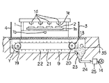
図1〜図3は第1実施形態であって、図1が集塵装置の平面を示し、図2が図1のA−A線に沿って切断した断面を示し、図3が図1のB−B線に沿って切断した断面を示す。これらの図において、ルーター加工装置1は、テーブル1aに遊技盤2が位置決め搭載されたことを検出する図外の遊技盤センサー、又は、当該遊技盤センサーに代えて作業者の操作でオン動作されるマニュアルスイッチの何れかが、遊技盤種別信号及び加工開始信号を、図外のコンピューターが内蔵された制御部に出力することにより、コンピューターが制御部の記憶装置に予め記憶された当該遊技盤2の機種に対応する加工データーより加工位置及び順序を抽出し、それらの加工位置及び順序に従ってY駆動部1b、XZ駆動部1c、刃物駆動部1dを駆動する。これらのY駆動部1b及びXZ駆動部1cの駆動により、刃物駆動部1dに取り付けられたルーター加工用の刃物1eと、テーブル1aの上の遊技盤2とが、平面内の縦横としてのX方向及びY方向に相対的に移動及び上下方向のZ方向に相対的に昇降動作する。又、刃物駆動部1dの駆動により、刃物1eが回転駆動する。これにより、刃物1eが遊技盤2に、例えば、センター役物用孔、ストップランプ用孔、賞球ランプ用孔、アタッカー用孔、サイドランプ用孔、入賞用孔、アウト用孔等の複数の開口を自動的に切削して形成する。これらの開口には、遊技盤2の上面より裏面(テーブル1aの側の面)に貫通する貫通孔の場合と、遊技盤2の裏面に未貫通な裏堀と呼ばれる窪みの場合とがある。刃物駆動部1dは、XZ駆動部1cの可動端に取り付けられたモーター1fと、モーター1f及び刃物1eを被覆する筒状の集塵カバー1gと、集塵カバー1gの上開口部に接続された集塵ダクト1hとを備え、集塵ダクト1hに接続した吸引式集塵機1iにより、モーター1fの出力端に取り付けられた刃物1eが駆動して遊技盤2に切削加工を行う際、刃物1eより舞い上がる切削屑を、刃物1e及びモーター1fと集塵カバー1gとの隙間を経由して集塵ダクト1hに吸引し、その吸引気流でモーター1fを冷却する。吸引式集塵機1iは、図外のファンをモーターで駆動して、集塵ダクト1hの内部に吸引用の空気流を生成し、この空気流に乗せて、切削屑を、集塵ダクト1hより図示を省略した屋外の分離室に導き、分離室のフィルターにより、切削屑と空気とを分別する。分別されて分離室に捕捉された切削屑はパイプにより図示を省略した屋外の焼却炉に供給され、分別されてフィルターを通過した清浄な空気は、排気口より屋外に排出される。
【0007】
第1実施形態の場合、ルーター加工装置1の周辺を左右及び後側の仕切り3,4,5で囲み、これらの仕切り3〜5より内側の設置面6に溝7,8,9を形成している。これらの溝7〜9は、ルーター加工装置1の左右及び後側に位置して平面視コ字形を呈し、左右の溝7,8を後側の溝9より浅く形成している。これらの溝7〜9の開口部を防柵ネット10で被覆すると共に、溝7〜9の内部に屑回収手段11,12,13,14を設けている。
【0008】
左右の溝7,8に設けられた屑回収手段11,12は、前端部及び後端部に配置されたスプロケット15,16と、これらのスプロケット15,16に無端状に巻掛けられたチェーン17と、チェーン17より外側に突出するようにチェーン17に取り付けられた多数の爪体18とを備えた搬送形態として形成され、スプロケット15,16の一方を図外のモーターで矢印Xで示す一方向に回転駆動することにより、防柵ネット10より溝7,8の内部に落下した切削屑を爪体18により溝7,8の前端部より後端部に向けて掻き集め、後端部より後側の溝9に払い落とす。
【0009】
後側の溝9に設けられた屑回収手段13は、左右方向の一端部及び他端部に配置されたスプロケット19,20と、これらのスプロケット19,20に無端状に巻掛けられたチェーン21と、チェーン21より外側に突出するようにチェーン21に取り付けられた多数の爪体22とを備えた搬送形態として形成され、スプロケット19,20の一方を図外のモーターで矢印Yで示す一方向に回転駆動することにより、防柵ネット10より溝9の内部に落下した切削屑を爪体22により一端部より他端部に向けて掻き集める。
【0010】
後側の溝9の他端部には、屑溜め23を、後側の溝9の底部よりも深く摺鉢状に堀下げている。この屑溜め23の底部には集塵ダクト24を接続している。この集塵ダクト24は、吸引式集塵機1iの集塵ダクト1hに弁25を介して接続している。よって、吸引式集塵機1iのファンが駆動した状態において、弁25を開弁動作することにより、屑溜め23の切削屑を集塵ダクト24より分離室に収集する。これらの集塵ダクト24と弁25及び吸引式集塵機1iにより屑回収手段14が吸引形態として形成されているが、それらの要素の内の集塵ダクト24を後側の溝9に設け、それ以外の要素としての弁25及び吸引式集塵機1iを屋外又は屋内の何れかに設けることもできる。
【0011】
第1実施形態の構造によれば、吸引式集塵機1iを吸引動作させ、弁25を閉弁動作した状態において、刃物1eにより遊技盤2に開口を切削加工する際、刃物1eより舞い上がる切削屑を刃物1eの周辺に設けた集塵ダクト1hで吸引する。1回のルーター加工が終了する毎に、作業者が、集塵ダクト1hで集塵し切れずにルーター加工装置1の上に落下した切削屑を、図外のエアーノズルから噴射される空気により、ルーター加工装置1の周辺に吹き飛ばす。この吹き飛ばされた切削屑が、仕切り3〜5に当たり、防柵ネット10を経由して溝7〜9に入る。そして、昼休み前や就業終了時又は一定時間毎等において、作業者が図外のマニュアルスイッチを操作する。これにより、屑回収手段11〜13を駆動すると共に弁25を開弁動作する。そして、左右側の屑回収手段11,12が左右の溝7,8に取り込まれた切削屑を後側の溝9に排出し、後側の屑回収手段13が後側の溝9に取り込まれた切削屑を屑溜め23に排出する。更に、吸引式集塵機1iが、屑溜め23に集められた切削屑を、集塵ダクト24により分離室に集塵することができる。
【0012】
要するに、第1実施形態では、ルーター加工装置1の周辺を左右及び後側の仕切り3〜5で囲み、これらの仕切り3〜5より内側に切削屑を取り込む溝7〜9を形成したので、刃物2の側の集塵ダクト1hで集塵し切れずにルーター加工装置1の周辺に吹き飛ばされる切削屑を、各仕切り3〜5よりも外側に飛散させずに、溝7〜9に捕捉することができる。
【0013】
又、溝7〜9の開口部を防柵ネット10で被覆したので、作業者がルーター加工装置1の保守点検時において、スパナやレンチ等のような工具をルーター加工装置1の周辺に落とした場合、防柵ネット10により工具の溝7〜9への落下を防止できる。
【0014】
溝7〜9の内部に屑回収手段11〜14を設けたので、それらの屑回収手段11〜14を昼休み前や就業終了時又は一定時間毎等の何れかに動作させることにより、切削屑を溝7〜9より除去できる。
【0015】
図4は、第2実施形態の溝30の内部に設けた屑回収手段31を溝30の長手方向に切断した断面を示す。溝30は第1実施形態の溝7〜9に相当するものであって、溝30の底部には、複数の捕捉樋32を形成し、互いに隣接する捕捉樋32の双方で形成される摺鉢形状の底部に排出ダクト33を接続し、これらの排出ダクト33を集塵ダクト24に個別に接続している。これらの捕捉樋32と排出ダクト33と集塵ダクト24と図3に示す弁25及び図2に示す吸引式集塵機1iにより、屑回収手段11〜14に相当する屑回収手段31を吸引形態に形成している。よって、第2実施形態によれば、屑回収手段31を昼休み前や就業終了時又は一定時間毎等の何れかに吸引動作させることにより、切削屑を溝30より除去できる。
【0016】
第1・第2実施形態では、屑回収手段11〜14,30を人為操作で動作したが、図3又は図4に仮想線で示すように、溝7〜9,30に屑量検出手段35を設け、この屑量検出手段35が溝7〜9,30に捕捉された切削屑が所定量を越えたことを検出することにより、その検出信号により屑回収手段の収集動作を開始すれば、溝7〜9,30からの切削屑の搬出を自動的に行うことができる。
【0017】
又、溝7〜9に設ける屑回収手段として搬送形態と吸引形態との双方を併用すれば、集塵に対する吸引動作の開始により、ルーター加工装置1が設置された建屋内部の負圧現象を軽減できる。
【図面の簡単な説明】
【図1】第1実施形態の集塵装置を示す平面図。
【図2】図1のA−A線に沿う断面図。
【図3】図1のB−B線に沿う断面図。
【図4】第2実施形態の屑回収手段を示す断面図。
【符号の説明】
1 ルーター加工装置
3〜5 仕切り
7〜9 溝
10 防柵ネット
11〜14,30 屑回収手段
35 屑量検出手段[0001]
TECHNICAL FIELD OF THE INVENTION
The present invention relates to a dust collector for a router processing apparatus for cutting an opening such as a through hole for a game ball or a hole for mounting a game function component on a game board having a design drawing on a surface thereof when manufacturing a game machine such as a pachinko machine. About.
[0002]
[Prior art]
The router processing device used in the manufacture of pachinko machines positions the game board on a table, and positions the table and the blades installed above the table relatively vertically and horizontally in a plane according to the position and order according to the processing data. While moving and relatively moving up and down, the blade is rotated to form an opening in the game board.
[0003]
[Problems to be solved by the invention]
In the conventional router processing equipment, the cutting dust flying up from the blade is suctioned by the dust collection duct provided around the blade, but every time the worker finishes the router processing, it drops from the game board onto the router processing apparatus The blown chips were blown off by air jetted from an air nozzle, and the blown chips were cleaned with a vacuum cleaner or a broom at the end of work.
[0004]
SUMMARY OF THE INVENTION Accordingly, an object of the present invention is to provide a dust collector for router processing for amusement machine manufacturing, which can collect cutting chips dropped around the router processing apparatus and improve production efficiency.
[0005]
[Means for Solving the Problems]
The dust collector of the router processing apparatus for manufacturing a game machine according to
[0006]
BEST MODE FOR CARRYING OUT THE INVENTION
1 to 3 show a first embodiment, in which FIG. 1 shows a plan view of a dust collector, FIG. 2 shows a cross section taken along line AA of FIG. 1, and FIG. 3 shows a cross section taken along line BB. In these figures, the
[0007]
In the case of the first embodiment, the periphery of the
[0008]
The waste collecting means 11 and 12 provided in the left and
[0009]
The waste collecting means 13 provided in the
[0010]
At the other end of the
[0011]
According to the structure of the first embodiment, when the opening of the
[0012]
In short, in the first embodiment, the periphery of the
[0013]
Also, since the openings of the
[0014]
Since the chip collecting means 11 to 14 are provided inside the
[0015]
FIG. 4 shows a cross section of the waste collecting means 31 provided inside the
[0016]
In the first and second embodiments, the waste collecting means 11 to 14 and 30 are manually operated. However, as shown by phantom lines in FIG. 3 or FIG. If the waste amount detection means 35 detects that the amount of cutting waste caught in the
[0017]
If both the conveyance mode and the suction mode are used together as the dust collecting means provided in the
[Brief description of the drawings]
FIG. 1 is a plan view showing a dust collector according to a first embodiment.
FIG. 2 is a sectional view taken along the line AA in FIG. 1;
FIG. 3 is a sectional view taken along the line BB of FIG. 1;
FIG. 4 is a sectional view showing a waste collecting means according to a second embodiment.
[Explanation of symbols]
DESCRIPTION OF
Claims (2)
Priority Applications (1)
| Application Number | Priority Date | Filing Date | Title |
|---|---|---|---|
| JP21486297A JP3547293B2 (en) | 1997-08-08 | 1997-08-08 | Dust collector for router processing for amusement machine production |
Applications Claiming Priority (1)
| Application Number | Priority Date | Filing Date | Title |
|---|---|---|---|
| JP21486297A JP3547293B2 (en) | 1997-08-08 | 1997-08-08 | Dust collector for router processing for amusement machine production |
Publications (2)
| Publication Number | Publication Date |
|---|---|
| JPH1158322A JPH1158322A (en) | 1999-03-02 |
| JP3547293B2 true JP3547293B2 (en) | 2004-07-28 |
Family
ID=16662796
Family Applications (1)
| Application Number | Title | Priority Date | Filing Date |
|---|---|---|---|
| JP21486297A Expired - Fee Related JP3547293B2 (en) | 1997-08-08 | 1997-08-08 | Dust collector for router processing for amusement machine production |
Country Status (1)
| Country | Link |
|---|---|
| JP (1) | JP3547293B2 (en) |
Families Citing this family (4)
| Publication number | Priority date | Publication date | Assignee | Title |
|---|---|---|---|---|
| JP4527270B2 (en) * | 2000-12-05 | 2010-08-18 | 株式会社平和 | Drilling device for game board |
| CN109227789A (en) * | 2018-09-28 | 2019-01-18 | 柳州市千山木业有限公司 | A kind of timber processing locating platform |
| CN110815443A (en) * | 2019-12-03 | 2020-02-21 | 中山市华盛家具制造有限公司 | Identification method and system for switching on and off of sawdust and PVC dust collection pipeline |
| JP7419130B2 (en) | 2020-03-24 | 2024-01-22 | 株式会社クボタ | electric work vehicle |
-
1997
- 1997-08-08 JP JP21486297A patent/JP3547293B2/en not_active Expired - Fee Related
Also Published As
| Publication number | Publication date |
|---|---|
| JPH1158322A (en) | 1999-03-02 |
Similar Documents
| Publication | Publication Date | Title |
|---|---|---|
| JP3547293B2 (en) | Dust collector for router processing for amusement machine production | |
| US4359801A (en) | Pick-up head for surface cleaning apparatus | |
| CN115284397B (en) | Wood chip separation equipment for wood processing | |
| JP2006183996A (en) | Air conditioner | |
| CN207859053U (en) | A kind of air-draft-type sheet fabrication debris collection device | |
| CN213888313U (en) | Do benefit to garbage collection's puncher | |
| JPH0524488Y2 (en) | ||
| CN209718236U (en) | A kind of dedusting cutter device applied to rock wool cutting processing | |
| CN100338399C (en) | Air conditioner having indoor unit with automatic air filter-cleaning function | |
| JPH11300701A (en) | Cutting device for plate material | |
| CN116673532A (en) | Aluminum slab ingot end milling device | |
| JP2006183997A (en) | Air conditioner | |
| JP2006183997A6 (en) | Air conditioner | |
| JP2006105439A (en) | Dust suction device control method for air-conditioner | |
| CN217620926U (en) | Dust removing device of plate cutting machine | |
| TWM612147U (en) | Mechanism capable of removing pests on surface of fruits | |
| JP3681477B2 (en) | Router processing equipment for the manufacture of gaming machines | |
| JP5708709B2 (en) | Coin milling machine | |
| JPH10151239A (en) | Router processing equipment for manufacturing game machine | |
| JPH0721866Y2 (en) | Radiator dust remover | |
| JP3640483B2 (en) | Router processing equipment for the manufacture of gaming machines | |
| CN219855070U (en) | Automatic edge trimming saw | |
| JPS6238105B2 (en) | ||
| CN218554780U (en) | Sand dust removal device | |
| JPH0569409A (en) | Device for collecting cut-dust in cutting machine |
Legal Events
| Date | Code | Title | Description |
|---|---|---|---|
| A521 | Written amendment |
Free format text: JAPANESE INTERMEDIATE CODE: A523 Effective date: 20040129 |
|
| TRDD | Decision of grant or rejection written | ||
| A01 | Written decision to grant a patent or to grant a registration (utility model) |
Free format text: JAPANESE INTERMEDIATE CODE: A01 Effective date: 20040413 |
|
| A61 | First payment of annual fees (during grant procedure) |
Free format text: JAPANESE INTERMEDIATE CODE: A61 Effective date: 20040413 |
|
| R150 | Certificate of patent or registration of utility model |
Free format text: JAPANESE INTERMEDIATE CODE: R150 |
|
| R250 | Receipt of annual fees |
Free format text: JAPANESE INTERMEDIATE CODE: R250 |
|
| FPAY | Renewal fee payment (event date is renewal date of database) |
Free format text: PAYMENT UNTIL: 20090423 Year of fee payment: 5 |
|
| FPAY | Renewal fee payment (event date is renewal date of database) |
Free format text: PAYMENT UNTIL: 20100423 Year of fee payment: 6 |
|
| FPAY | Renewal fee payment (event date is renewal date of database) |
Free format text: PAYMENT UNTIL: 20110423 Year of fee payment: 7 |
|
| FPAY | Renewal fee payment (event date is renewal date of database) |
Free format text: PAYMENT UNTIL: 20110423 Year of fee payment: 7 |
|
| FPAY | Renewal fee payment (event date is renewal date of database) |
Free format text: PAYMENT UNTIL: 20130423 Year of fee payment: 9 |
|
| FPAY | Renewal fee payment (event date is renewal date of database) |
Free format text: PAYMENT UNTIL: 20140423 Year of fee payment: 10 |
|
| R250 | Receipt of annual fees |
Free format text: JAPANESE INTERMEDIATE CODE: R250 |
|
| R250 | Receipt of annual fees |
Free format text: JAPANESE INTERMEDIATE CODE: R250 |
|
| LAPS | Cancellation because of no payment of annual fees |