JP3546552B2 - Retaining structure of slat curtain in shutter - Google Patents
Retaining structure of slat curtain in shutter Download PDFInfo
- Publication number
- JP3546552B2 JP3546552B2 JP20590695A JP20590695A JP3546552B2 JP 3546552 B2 JP3546552 B2 JP 3546552B2 JP 20590695 A JP20590695 A JP 20590695A JP 20590695 A JP20590695 A JP 20590695A JP 3546552 B2 JP3546552 B2 JP 3546552B2
- Authority
- JP
- Japan
- Prior art keywords
- guide groove
- slat
- groove
- edge
- claw
- Prior art date
- Legal status (The legal status is an assumption and is not a legal conclusion. Google has not performed a legal analysis and makes no representation as to the accuracy of the status listed.)
- Expired - Fee Related
Links
Images


Landscapes
- Operating, Guiding And Securing Of Roll- Type Closing Members (AREA)
Description
【0001】
【発明の属する技術分野】
本発明は、スラットカーテンが風圧などによってガイドレールから抜け出すのを防止するシャッターにおけるスラットカーテンの抜止構造に関するものである。
【0002】
【従来の技術】
シャッターのスラットカーテンが、閉鎖状態の際、風などの外力によって撓み、スラットカーテンの昇降の案内を行うガイドレールから両側縁が抜け出て外れるのを防止する抜け止め防止構造については、従来、種々の公知技術が知られている。
【0003】
例えば、実開昭62−85688号公報に開示されている構造では、スラットカーテンを構成するスラットの両側端部に、ガイドレール内へ突出する先端がL字状に折曲形成されている抜止爪を設け、スラットカーテンが撓んだ際に、この抜止爪をガイドレールの内縁の突条部に係合させることで、抜け止めとさせるようになっている。
【0004】
【発明が解決しようとする課題】
しかしながら、上述した従来の抜け止め防止構造では、ガイドレールが変形しないことを前提としているが、このガイドレールが薄肉なアルミ型材にて構成されている場合、スラットカーテンの撓みに影響されてガイドレールが変形することがある。
【0005】
すなわち、このスラットカーテンの撓みによりガイドレールの開口溝幅が拡張されてしまい、ガイドレール内の突条部とスラットカーテンの抜止爪との係合が行われず、スラットカーテンがガイドレールより抜け出てしまうという問題があった。
【0006】
そこで本発明は、上記問題点を解消するために、風などの外力に対してスラットカーテンが撓んだ際に、このスラットカーテンがガイドレールから抜け出すことがないシャッターにおけるスラットカーテンの抜止構造を提供することを目的としている。
【0007】
【課題を解決するための手段】
次に、上記の課題を解決するための手段を、実施の形態に対応する図面を参照して説明する。
この発明のシャッターにおけるスラットカーテンの抜止構造は、図1乃至図3、図6、又は、図7の実施の形態に示されるように、上下縁に形成された係合連結部21,22にて互いに連結された複数のスラット2より構成されるスラットカーテン1の昇降を案内するガイド溝9の少なくとも一方の開口縁部10に、該ガイド溝9の開口からガイド溝9の奥方向に向いて延出する係合条片13が配設され、該係合条片13とガイド溝9の側壁とでガイド溝9の奥方向に開口する溝14が形成され、断面略G字状に形成されたガイドレール8と、
基部4と爪部5とが直角をなして一体形成された略L字形状に形成されているとともに、爪部5の先端縁6がさらに直角に折曲形成されて鉤形状に形成された規制爪片3を具備し、該規制爪片3は、前記ガイドレール8のガイド溝9内を移動する前記スラット2の端部2aに前記基部4が固定されて設けられ、該スラット2の板面より突出するとともに、先端縁6が前記係合条片13の延出方向と逆の方向に向いて延出し、前記ガイド溝9内の前記溝14と係脱自在となることを特徴としている。
また、図4の実施の形態に示すように、規制爪片3を、スラット2の端部2aを延出形成させるとともに、その延出した端部2aを折曲して、その先端縁6をガイドレール8内の前記係合条片13の延出方向と逆の方向に延出するように略鉤状に形成させることができる。
また、図5の実施の形態に示すように、規制爪片3を、スラット2の端部2aにおける板面を、一側縁を残して打ち抜き、自由端縁である先端縁6を該板面より突出させるように折曲形成させ、この先端縁6をさらに折曲して形成させることができる。
【0008】
このような構成により、風などの外力によってスラットカーテン1が撓んだ場合、スラットカーテン1のスラット2の端部2aに設けられた規制爪片3と、ガイドレール8内の溝14とが、確実に係合しあい、スラットカーテン1がガイドレール8から抜け出すことがない。
【0009】
【発明の実施の形態】
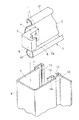
図1は本発明によるシャッターにおけるスラットカーテンの抜止構造の実施の形態を示す分解斜視図、図2は同平断面図である。
【0010】
まず、シャッターのスラットカーテン1は、複数の横長な略短冊状のスラット2で構成されており、各スラット2の上下端縁部に形成されている係合連結部としてのカール部21,22にて互いが回動自在となるように上下に連続して連結されて構成されている。
【0011】
連結された各スラット2の所定枚数毎の複数枚には、左右両端2aに規制爪片3が設けられている。
ここで、規制爪片3が設けられる所定枚数毎の複数枚とは、スラットカーテン1を巻き取った状態で、各巻層における隣り合う巻層とならない枚数毎の複数枚のスラット2とされることが好ましい。
【0012】
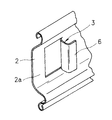
この規制爪片3は、例えば、ガラス繊維が混入された合成樹脂などよりなり、図1及び図2に示すように、基部4と爪部5とが直角をなして一体形成された略L字形状に形成されているとともに、爪部5の先端縁6がさらに直角に折曲形成されて、鉤形状に形成されている。
【0013】
そして、この規制爪片3は、スラット2の端部2aに、基部4をリベットやステイプル、接着や溶着などの固定手段7にて固定され設けられる。
固定された状態においては、爪部5が屋内側となるスラット2の面に対して突出するように固定されるとともに、先端縁6の向きがスラット2の中心方向となるように設定される。
なお、本実施の形態では、爪部5の基部4寄りを厚肉に形成している。
【0014】
次に、上記スラットカーテン1の昇降を案内する左右一対のガイドレール8は、建物などの開口の左右縁部に垂直に立設され、図1に示すように、それぞれ互いに向き合う一側が開口し、ガイド溝9とされて断面略コ字状に形成されている。
【0015】
また、このガイドレール8のガイド溝9の開口両縁部10,11における対向する内面には、取付溝部12が形成され、スラットカーテン1が昇降する際の擦れ防止及び防音のためのモヘア(図示せず)などが設けられている。
【0016】
さらに、このガイドレール8のガイド溝9における屋内側となる一方の開口縁部10には、前記取付溝部12と一体となる係合条片13が設けられている。
【0017】
この係合条片13は、ガイド溝9内において、ガイド溝9の開口側からガイド溝9の奥方向に向いて延出するように形成されるとともに、ガイドレール8の長手方向に沿って連続して形成されている。
【0018】
そして、この係合条片13とガイド溝9の内側壁にて、奥方向に開口する小幅な溝14が形成される。
【0019】
従ってこのように構成されたスラットカーテンの抜止構造では、通常の動作時では、図2に示すように、スラットカーテン1の両端部2aは左右各ガイドレール8のガイド溝9内に案内されて、昇降(開閉)動作が行われる。
このとき、スラットカーテン1の規制爪片3の先端縁6と、ガイドレール8の係合条片13とは、それぞれ逆方向に延出するような略向き合う位置関係で互いに係合することなく、ガイドレール8内をスラットカーテン1が移動する。
【0020】
そして、閉鎖状態となっているスラットカーテン1に、風などの外力が加わり、スラットカーテン1が煽られ撓むと、図3に示すように、スラット2が湾曲し、スラット2の端部2aに設けられている規制爪片3の先端縁6が、ガイドレール8のガイド溝9内の係合条片13による溝14内に入り互いに係合する。
【0021】
この抜止構造によれば、規制爪片3と係合条片13とがそれぞれ断面鉤状に形成されているので、互いに噛み合うように係合することとなり、確実にスラットとガイドレール8とが係合状態となって、風などの外力でスラットカーテン1が撓んでも、スラット2の端部2aがガイドレール8から抜け出てしまうのを防止される。
【0022】
特に、風が強い際にスラット2の撓み量が大きくなり、ガイドレール8の側壁をも撓ませてしまう(図3参照)場合であっても、スラット2の規制爪片3が係合条片13の溝14内に係合するので、ガイドレール8からのスラット2の抜け出しを完全に防止することが可能となる。
【0023】
また、スラット2の厚さ方向に大きく突出せずに規制爪片3を構成させることが可能なことから、ガイドレール8の幅を拡張せずに抜止構造を構成することが可能となり、建物側へのガイドレール取付面積の省スペース化を図ることが可能となる。
【0024】
なお、上述した実施の形態では、規制爪片3を、スラット2と別体構造とした例について述べたが、この規制爪片3は、スラット2と一体な構造としてもよい。
【0025】
すなわち、図4に示すように、スラット2の端部2aを翼状に延出形成させるとともに、その延出した翼状端部2aを折曲して、先端縁6をガイドレール8内の係合条片13の延出方向と逆の略対向方向に延出するように略鉤状に形成し、規制爪片3とさせる。
また、スラット2の端部2aにおける板面をプレス加工などの処理で、図5に示すように、一側縁を残して打ち抜き、自由端縁側である先端縁6を板面より突出させるように折曲形成させ、この先端縁6をさらに折曲し規制爪片3としてもよい。
【0026】
また、上述した実施の形態において、スラット2の長さ方向(左右幅方向)にスラット端縁より突出する規制爪片3の長さが短く設定されているが、図6に示すように、スラット2の端縁より外方に延出させ設ける構成としてもよい。
これによれば、スラットカーテン1を巻き取った状態で、各スラット2同士重なりあって巻き取られることとなるので、巻径が大きくならなくなる。
【0027】
さらに、上述した実施の形態では、抜止構造を構成する規制爪片3が設けられるスラット2の形状を上下縁の係合連結部がカール部21,22とされた例について述べたが、図7に示すように、消音材が充填される中空部2bを有し、係合連結部として上縁にカール部21が形成され、下縁に連結溝22が形成されたスラット2に、この規制爪片3を固定させる構成としてもよい。
この場合、規制爪片3の基部4を中空部2bに嵌入させ固定させる。
【0028】
また、上述した実施の形態では、規制爪片3の爪部5を屋内側方向に突出させた構成について述べたが、屋外側に突出させてもよく、この場合は、ガイドレール8の係合条片13の設けられる位置を屋外側の側壁とさせる。
なお、ガイドレール8のガイド溝9内の係合条片13を両側壁に設け、それぞれに溝14を形成させて、スラット2の端部2aにおける規制爪片3の爪部5の突出方向を、スラット一枚毎に、屋内側と屋外側との両方向となるように構成させてもよい。
【0030】
また、上述した実施の形態では、ガイドレール8のガイド溝9内に、係合条片13をガイドレール8と一体に形成させた例について述べたが、それぞれ別体構成として、係合条片13をガイドレール8に固定させる構造としてもよい。
【0031】
【発明の効果】
以上説明したように本発明によるシャッターにおけるスラットカーテンの抜止構造では、閉鎖状態となっているスラットカーテンに、風などの外力が加わり、スラットカーテンが煽られ撓んだ際に、スラットの端部に設けられている規制爪片の先端縁が、ガイドレールのガイド溝内に配設された係合条片による溝内に入り互いに係合するので、スラットの端部がガイドレールのガイド溝から抜け出て外れてしまうのを防止することができるという効果がある。
【0032】
すなわち、スラットに設けられている規制爪片と、ガイドレールの係合条片との延出方向が互いに向き合う逆方向とされている略鉤状に形成されていることから、規制爪片の先端縁が、係合条片による溝内に、互いに噛み合うように係合することとなり、確実にスラットとガイドレールとが係合状態となって、スラットの端部がガイドレールより容易に抜け出さないという効果を得られる。
【0033】
特に、風が強い際にスラットの撓み量が大きくなり、ガイドレールの側壁をも撓ませてしまう場合であっても、スラットの規制爪片が係合条片の溝内に係合するので、ガイドレールからのスラットの抜け出しを完全に防止することができるという効果がある。
【図面の簡単な説明】
【図1】本発明によるシャッターにおけるスラットカーテンの抜止構造の実施の形態を示す分解斜視図
【図2】同抜止構造の平断面図
【図3】同抜止構造の動作を示す平断面図
【図4】他の実施の形態による抜止構造の斜視図
【図5】他の実施の形態による抜止構造の斜視図
【図6】他の実施の形態による抜止構造の平断面図
【図7】他の実施の形態による抜止構造の分解斜視図
【符号の説明】
1…スラットカーテン
2…スラット
2a…端部
3…規制爪片
6…先端縁
8…ガイドレール
9…ガイド溝
10,11…開口縁部
13…係合条片
14…溝
21,22…係合連結部[0001]
TECHNICAL FIELD OF THE INVENTION
The present invention relates to a slat curtain retaining structure for a shutter that prevents a slat curtain from coming off a guide rail due to wind pressure or the like.
[0002]
[Prior art]
When the shutter slat curtain is closed, the slat curtain bends due to external force such as wind, and both sides of the slat curtain are prevented from coming off and coming off from the guide rail that guides the slat curtain up and down. Known techniques are known.
[0003]
For example, in the structure disclosed in Japanese Utility Model Laid-Open Publication No. 62-85688, a retaining claw having an L-shaped bent end protruding into a guide rail is formed on both side ends of a slat constituting a slat curtain. When the slat curtain bends, the retaining pawl is engaged with a ridge on the inner edge of the guide rail to prevent the slat curtain from coming off.
[0004]
[Problems to be solved by the invention]
However, in the above-mentioned conventional retaining prevention structure, it is assumed that the guide rail is not deformed. However, when this guide rail is made of a thin aluminum material, the guide rail is affected by the deflection of the slat curtain. May be deformed.
[0005]
That is, the opening groove width of the guide rail is expanded due to the bending of the slat curtain, the ridges in the guide rail do not engage with the retaining claws of the slat curtain, and the slat curtain comes off from the guide rail. There was a problem.
[0006]
In order to solve the above problems, the present invention provides a slat curtain retaining structure for a shutter in which the slat curtain does not come out of a guide rail when the slat curtain is bent by an external force such as wind. It is intended to be.
[0007]
[Means for Solving the Problems]
Next, means for solving the above problems will be described with reference to the drawings corresponding to the embodiments.
The retaining structure of the slat curtain in the shutter according to the present invention is, as shown in the embodiment of FIG. 1 to FIG. 3, FIG. 6, or FIG. At least one
The
Further, as shown in the embodiment of FIG. 4, the
As shown in the embodiment of FIG. 5, the regulating
[0008]
With such a configuration, when the
[0009]
BEST MODE FOR CARRYING OUT THE INVENTION
FIG. 1 is an exploded perspective view showing an embodiment of a slat curtain retaining structure in a shutter according to the present invention, and FIG. 2 is a plan sectional view thereof.
[0010]
First, the
[0011]
Restricting
Here, the plurality of
[0012]
The restricting
[0013]
The restricting
In the fixed state, the
In the present embodiment, the
[0014]
Next, a pair of left and
[0015]
Further, mounting
[0016]
Further, an
[0017]
The
[0018]
Then, a
[0019]
Accordingly, in the slat curtain retaining structure thus configured, both ends 2a of the
At this time, the
[0020]
Then, when an external force such as wind is applied to the
[0021]
According to this retaining structure, since the regulating
[0022]
In particular, when the wind is strong, the amount of deflection of the
[0023]
In addition, since the restricting
[0024]
In the above-described embodiment, an example has been described in which the restricting
[0025]
That is, as shown in FIG. 4, the
In addition, as shown in FIG. 5, the plate surface at the
[0026]
Further, in the above-described embodiment, the length of the regulating
According to this, in a state where the
[0027]
Furthermore, in the above-described embodiment, the example in which the engaging connection portions at the upper and lower edges are curled
In this case, the
[0028]
Further, in the above-described embodiment, the configuration in which the
The engaging
[0030]
In the above-described embodiment, the example in which the engaging
[0031]
【The invention's effect】
As described above, in the retaining structure of the slat curtain in the shutter according to the present invention, when an external force such as wind is applied to the slat curtain in the closed state, when the slat curtain is bent and bent, the slat curtain ends. The leading edge of the provided regulating claw piece enters the groove formed by the engaging strip disposed in the guide groove of the guide rail and engages with each other, so that the end of the slat comes out of the guide groove of the guide rail. There is an effect that it can be prevented that it comes off.
[0032]
That is, since the regulating claw provided on the slat and the engaging strip of the guide rail are formed in a substantially hook shape in which the extending directions are opposite to each other, the leading end of the regulating claw is formed. The edges are engaged so as to mesh with each other in the grooves formed by the engaging strips, so that the slats and the guide rails are securely engaged with each other, and the ends of the slats do not easily come out of the guide rails. The effect can be obtained.
[0033]
In particular, when the wind is strong, the amount of deflection of the slat increases, and even when the side wall of the guide rail also bends, the slat regulating claw piece engages in the groove of the engagement strip, There is an effect that the slat can be completely prevented from coming off from the guide rail.
[Brief description of the drawings]
1 is an exploded perspective view showing an embodiment of a slat curtain retaining structure in a shutter according to the present invention; FIG. 2 is a plan sectional view of the retaining structure; FIG. 3 is a plan sectional view showing the operation of the retaining structure; 4 is a perspective view of a retaining structure according to another embodiment. FIG. 5 is a perspective view of a retaining structure according to another embodiment. FIG. 6 is a cross-sectional plan view of a retaining structure according to another embodiment. Exploded perspective view of a retaining structure according to an embodiment.
DESCRIPTION OF
Claims (3)
基部と爪部とが直角をなして一体形成された略L字形状に形成されているとともに、爪部の先端縁がさらに直角に折曲形成されて鉤形状に形成された規制爪片を具備し、該規制爪片は、前記ガイドレールのガイド溝内を移動する前記スラットの端部に前記基部が固定されて設けられ、該スラットの板面より突出するとともに、先端縁が前記係合条片の延出方向と逆の方向に向いて延出し、前記ガイド溝内の前記溝と係脱自在となることを特徴とするシャッターにおけるスラットカーテンの抜止構造。At least one opening edge of a guide groove that guides the elevation of a slat curtain composed of a plurality of slats connected to each other by engagement connection portions formed on upper and lower edges, from the opening of the guide groove to the guide groove. A guide rail in which an engagement strip extending in the depth direction is provided, and a groove that opens in the depth direction of the guide groove is formed by the engagement strip and a side wall of the guide groove,
The base portion and the claw portion are formed in a substantially L-shape in which the base portion and the claw portion are formed integrally at a right angle, and the claw portion further includes a regulating claw piece formed by bending a right angle at a right angle and forming a hook shape. The restricting pawl is provided with the base fixed to an end of the slat moving in the guide groove of the guide rail, protruding from the plate surface of the slat, and having a leading edge formed by the engaging strip. extension extending toward the direction opposite, the retaining structure of the slat curtain in the shutter to the groove and characterized by a disengageably of the guide groove of the piece.
スラットの端部を延出形成させるとともに、その延出した端部を折曲して、その先端縁をガイドレール内の前記係合条片の延出方向と逆の方向に延出するように略鉤状に形成した規制爪片と、を具備し、前記規制爪片の先端縁が前記ガイド溝内の前記溝と係脱自在となることを特徴とするシャッターにおけるスラットカーテンの抜止構造。The end of the slat is formed so as to be extended, the extended end is bent, and the leading end edge is extended in the direction opposite to the extending direction of the engaging strip in the guide rail. And a restricting claw formed in a substantially hook shape, wherein a distal end edge of the restricting claw is detachable from the groove in the guide groove.
スラットの端部における板面を、一側縁を残して打ち抜き、自由端縁である先端縁を該板面より突出させるように折曲形成させ、この先端縁をさらに折曲して形成した規制爪片と、を具備し、前記規制爪片の先端縁が前記ガイド溝内の前記溝と係脱自在となることを特徴とするシャッターにおけるスラットカーテンの抜止構造。The plate surface at the end of the slat is punched out, leaving one side edge, and the leading edge, which is a free edge, is bent and formed so as to project from the plate surface, and the leading edge is further bent and formed. Claw pieces, wherein a leading edge of the regulation claw pieces is freely engageable with and disengageable from the grooves in the guide grooves.
Priority Applications (1)
| Application Number | Priority Date | Filing Date | Title |
|---|---|---|---|
| JP20590695A JP3546552B2 (en) | 1995-08-11 | 1995-08-11 | Retaining structure of slat curtain in shutter |
Applications Claiming Priority (1)
| Application Number | Priority Date | Filing Date | Title |
|---|---|---|---|
| JP20590695A JP3546552B2 (en) | 1995-08-11 | 1995-08-11 | Retaining structure of slat curtain in shutter |
Publications (2)
| Publication Number | Publication Date |
|---|---|
| JPH0953376A JPH0953376A (en) | 1997-02-25 |
| JP3546552B2 true JP3546552B2 (en) | 2004-07-28 |
Family
ID=16514719
Family Applications (1)
| Application Number | Title | Priority Date | Filing Date |
|---|---|---|---|
| JP20590695A Expired - Fee Related JP3546552B2 (en) | 1995-08-11 | 1995-08-11 | Retaining structure of slat curtain in shutter |
Country Status (1)
| Country | Link |
|---|---|
| JP (1) | JP3546552B2 (en) |
Families Citing this family (3)
| Publication number | Priority date | Publication date | Assignee | Title |
|---|---|---|---|---|
| KR100411633B1 (en) * | 2001-08-02 | 2003-12-18 | 대업(주) | A shutter prevented separation |
| JP4596818B2 (en) * | 2004-05-25 | 2010-12-15 | 文化シヤッター株式会社 | Switchgear |
| JP6431722B2 (en) * | 2014-08-18 | 2018-11-28 | 文化シヤッター株式会社 | Shutter curtain structure |
-
1995
- 1995-08-11 JP JP20590695A patent/JP3546552B2/en not_active Expired - Fee Related
Also Published As
| Publication number | Publication date |
|---|---|
| JPH0953376A (en) | 1997-02-25 |
Similar Documents
| Publication | Publication Date | Title |
|---|---|---|
| WO2019037834A1 (en) | An elongated support member and a cover for being connected to the support member | |
| JP3546552B2 (en) | Retaining structure of slat curtain in shutter | |
| JP2008512584A (en) | Awning blind blind plate | |
| JP3787932B2 (en) | Shut-off structure of slat curtain in shutter | |
| JP2002295148A (en) | Winding type closing device for building | |
| US4198453A (en) | Weather seal and method of making same | |
| JP3596141B2 (en) | Retaining structure of slat curtain in shutter | |
| JP2002201876A (en) | Shutter curtain retaining structure | |
| JP2602406Y2 (en) | Shutter structure | |
| JPH0128236Y2 (en) | ||
| JP3635781B2 (en) | Shutter guide rail structure | |
| JP3479741B2 (en) | Shutter curtain retaining structure | |
| JP3543446B2 (en) | Retaining structure of slat curtain in shutter | |
| JP3007212U (en) | Shutter slat structure | |
| JPH0650639Y2 (en) | Wind-up screen device | |
| JPH1181830A (en) | Guide rail structure | |
| JPH0729197Y2 (en) | Securing structure for guide rails of architectural shutters | |
| JP2619960B2 (en) | Shutter guide structure | |
| JP2004060307A (en) | Retaining structure of shutter curtain for architectural shutter | |
| JPH037506Y2 (en) | ||
| JP3914483B2 (en) | Switchgear | |
| JP2518731B2 (en) | Shutter-cart for building | |
| JP3826343B2 (en) | Architectural shutter | |
| JP3820563B2 (en) | Architectural shutter | |
| JP3391714B2 (en) | Screen device for window sash |
Legal Events
| Date | Code | Title | Description |
|---|---|---|---|
| TRDD | Decision of grant or rejection written | ||
| A01 | Written decision to grant a patent or to grant a registration (utility model) |
Free format text: JAPANESE INTERMEDIATE CODE: A01 Effective date: 20040323 |
|
| A61 | First payment of annual fees (during grant procedure) |
Free format text: JAPANESE INTERMEDIATE CODE: A61 Effective date: 20040405 |
|
| R150 | Certificate of patent or registration of utility model |
Free format text: JAPANESE INTERMEDIATE CODE: R150 |
|
| S531 | Written request for registration of change of domicile |
Free format text: JAPANESE INTERMEDIATE CODE: R313531 |
|
| R350 | Written notification of registration of transfer |
Free format text: JAPANESE INTERMEDIATE CODE: R350 |
|
| R250 | Receipt of annual fees |
Free format text: JAPANESE INTERMEDIATE CODE: R250 |
|
| FPAY | Renewal fee payment (event date is renewal date of database) |
Free format text: PAYMENT UNTIL: 20130423 Year of fee payment: 9 |
|
| FPAY | Renewal fee payment (event date is renewal date of database) |
Free format text: PAYMENT UNTIL: 20130423 Year of fee payment: 9 |
|
| FPAY | Renewal fee payment (event date is renewal date of database) |
Free format text: PAYMENT UNTIL: 20150423 Year of fee payment: 11 |
|
| LAPS | Cancellation because of no payment of annual fees |