JP3546292B2 - Air-fuel ratio control device for internal combustion engine - Google Patents
Air-fuel ratio control device for internal combustion engine Download PDFInfo
- Publication number
- JP3546292B2 JP3546292B2 JP26522698A JP26522698A JP3546292B2 JP 3546292 B2 JP3546292 B2 JP 3546292B2 JP 26522698 A JP26522698 A JP 26522698A JP 26522698 A JP26522698 A JP 26522698A JP 3546292 B2 JP3546292 B2 JP 3546292B2
- Authority
- JP
- Japan
- Prior art keywords
- air
- fuel ratio
- amount
- skip
- rich
- Prior art date
- Legal status (The legal status is an assumption and is not a legal conclusion. Google has not performed a legal analysis and makes no representation as to the accuracy of the status listed.)
- Expired - Fee Related
Links
Images

Classifications
-
- Y—GENERAL TAGGING OF NEW TECHNOLOGICAL DEVELOPMENTS; GENERAL TAGGING OF CROSS-SECTIONAL TECHNOLOGIES SPANNING OVER SEVERAL SECTIONS OF THE IPC; TECHNICAL SUBJECTS COVERED BY FORMER USPC CROSS-REFERENCE ART COLLECTIONS [XRACs] AND DIGESTS
- Y02—TECHNOLOGIES OR APPLICATIONS FOR MITIGATION OR ADAPTATION AGAINST CLIMATE CHANGE
- Y02T—CLIMATE CHANGE MITIGATION TECHNOLOGIES RELATED TO TRANSPORTATION
- Y02T10/00—Road transport of goods or passengers
- Y02T10/10—Internal combustion engine [ICE] based vehicles
- Y02T10/40—Engine management systems
Landscapes
- Electrical Control Of Air Or Fuel Supplied To Internal-Combustion Engine (AREA)
- Combined Controls Of Internal Combustion Engines (AREA)
- Feedback Control In General (AREA)
Description
【0001】
【発明の属する技術分野】
本発明は、内燃機関に供給される可燃混合気の空燃比を最適化すべくフィードバック制御を行う内燃機関の空燃比制御装置に関する。
【0002】
【従来の技術】
車載用内燃機関(エンジン)の運転状態を制御する装置の一つとして、エンジンの燃焼室に供給される混合気の空燃比を制御する空燃比制御装置がある。一般に、エンジンに要求される空燃比はエンジンの回転速度、負荷状態及び暖機状態等に応じて変化する。そこでこの空燃比制御装置では、電子制御装置を通じて燃料噴射装置(燃料噴射弁)を制御することにより、燃焼室に供給される燃料量を補正して、混合気の空燃比を調整する。この調整により、エンジンの各種の運転条件に対応してエンジンの出力安定性やドライバビリティ等の向上が図られるとともに、排気特性が最適化される。
【0003】
ここで、この空燃比制御装置による空燃比のフィードバック制御は、具体的には以下のようなメカニズムに基づいて実行される。
すなわち、空燃比フィードバック制御に際しては先ず、エンジン回転数や吸気量等の運転状態パラメータに基づいて基本となる燃料噴射量(時間)が算出され、その基本燃料噴射量に、空燃比フィードバック補正係数、空燃比学習値、及びその他の各種運転状態に基づく補正係数を加味した目標燃料噴射量(時間)が決定される。空燃比フィードバック補正係数は、前回の燃料噴射に係る空燃比の理論空燃比(若しくは目標とする空燃比)に対するずれ量に対応するものであり、今回の燃料噴射に係る空燃比を理論空燃比により近づけるための補正係数である。
【0004】
そして、エンジンの排気系に設けられた空燃比センサ(酸素センサ)からの検出信号に基づいて算出される空燃比が理論空燃比より高ければ、燃料噴射量を増大し、低ければ減少させるという態様で燃料噴射量の補正を周期的に繰り返す。
【0005】
【発明が解決しようとする課題】
ところで、こうしたメカニズムに基づき空燃比を制御する装置にあっては、フィードバック制御によって補正量の増減を行うにあたり、燃焼室から酸素センサまでのガス輸送時間や酸素センサの応答時間に起因する応答遅れが生じる。そこで通常、燃料噴射量の補正態様を増大から減少、若しくは減少から増大に反転させる際には、この応答遅れを見込んで所定量スキップさせるスキップ制御、及びこのスキップさせた補正量を徐変させる積分制御を行うことにより、制御系の応答性を高めるようにしている。ただし、積分制御時の補正量徐変に係る変化率は、大きすぎれば制御波形の振幅を大きくしてしまい、小さすぎればリッチ側へのスキップとリーン側へのスキップとのインターバルを遅延させ制御波形の周波数を低下させてしまう。そしていずれの場合も、トルク変動の増大やドライバビリティの低下を促し、排気特性を悪化させてしまうこととなる。このため、前記スキップ制御に係るスキップ量や積分制御時の補正量徐変に係る変化率を常に最適な数値に設定することが緻密な空燃比フィードバック制御には不可欠となっている。
【0006】
なお従来、例えば特開昭58−53661号公報にみられるように、制御空燃比が排気浄化性の上で最適な空燃比となるよう、スキップ補正量や積分補正量を空燃比補正量の増大側と減少側とで非対称化することもなされているが、この場合であれ、上記応答遅れに起因する制御波形の振幅の増大化や周波数の低下は免れない。
【0007】
本発明は、こうした実情に鑑みてなされたものであり、その目的とするところは、空燃比フィードバック制御に係る制御波形の最適化を図り、ひいてはトルク変動の更なる抑制や排気特性の更なる向上を図ることのできる内燃機関の空燃比制御装置を提供することにある。
【0008】
【課題を解決するための手段】
上記の目的を達成するために、請求項1に記載の発明は、内燃機関の排気系に設けられて当該内燃機関の排気空燃比を検出する空燃比センサを有し、その検出される排気空燃比がリッチとリーンとの間で反転したときにスキップ制御されるとともに、その後積分制御されて更新される空燃比補正量に基づいて内燃機関に供給される混合気の空燃比をフィードバック制御する内燃機関の空燃比制御装置において、前記スキップ制御に際し、そのスキップ量を所定量増大させるとともに、増大させる前のスキップ量に基づき前記積分制御により算出される空燃比補正量が該増大したスキップ量をもって更新された空燃比補正量になるまでは、同増大したスキップ量をもって更新された空燃比補正量に基づき前記空燃比を補正する補正手段を備えることを要旨とする。
【0009】
同構成によれば、制御波形の振幅は抑制しつつ、スキップ制御による補正量の変動範囲のみを拡大することとなり、制御波形の周波数も増大することとなる。この結果、空燃比フィードバック制御の精度が増し、排気特性も一層向上するようになる。
【0011】
請求項2記載の発明は、請求項1記載の内燃機関の空燃比制御装置において、前記補正手段は、前記増大させる前のスキップ量に基づき前記積分制御により算出される空燃比補正量が前記増大したスキップ量をもって更新された空燃比補正量になるまでの期間に前記検出される排気空燃比がリーンからリッチまたはリッチからリーンに反転したときには、前記増大させる前のスキップ量に基づき前記積分制御により算出される空燃比補正量を基準量として前記所定量のスキップ制御をおこなうことを要旨とする。
【0012】
同構成によれば、酸素センサからの検出信号がリッチからリーンに反転する周期が短い場合には空燃比がリッチずれすることを好適に抑制し、逆にリーンからリッチに反転する周期が短い場合には空燃比がリーンずれすることを好適に抑制することにより、空燃比フィードバック制御に係る制御中心の安定性を向上させることができるようになる。
【0013】
請求項3記載の発明は、請求項2記載の内燃機関の空燃比制御装置において、前記補正手段は、前記増大させる前のスキップ量に基づき前記積分制御により算出される空燃比補正量が前記増大したスキップ量をもって更新された空燃比補正量になるまでの期間に前記検出される排気空燃比がリッチからリーンに反転したときには、前記増大したスキップ量をもって更新された空燃比補正量を基準量として前記スキップ制御をおこなうことを要旨とする。
【0014】
同構成によれば、酸素センサからの検出信号がリッチ及びリーン間で反転する周期が短い場合、空燃比のリッチずれの抑制と空燃比フィードバック制御に係る制御中心の安定化が確実に行われるようになる。
【0015】
請求項4記載の発明は、請求項1〜3の何れかに記載の内燃機関の空燃比制御装置において、前記補正手段は、前記検出される排気空燃比の反転周期が所定時間以下であるときには、リッチからリーンへのスキップ制御に係るスキップ量と、リーンからリッチへのスキップ制御に係るスキップ量とを等量とすることを要旨とする。
【0016】
同構成によれば、インジェクタの流動特性や吸気系内での空気分配、パージ分配の不具合に起因して空燃比補正量の制御波形にチャタリングが生じたときに、このチャタリング発生時に空燃比補正量の制御波形が非対称形である場合であれ、制御波形の中心がずれてしまうことを好適に抑制することができるようになる。
【0017】
請求項5記載の発明は、請求項1〜3の何れかに記載の内燃機関の空燃比制御装置において、前記補正手段は、前記空燃比をリッチ側に補正するときにのみ、前記態様で設定される空燃比補正量に基づく補正を行うことを要旨とする。
【0018】
空燃比フィードバック制御系の応答遅れを生じさせる要因の一つである酸素センサの応答時間は、実際の空燃比がリーンからリッチに反転するときに比べ、リッチからリーンに反転するときの方が長いことが知られている。この酸素センサの応答時間においてみられる偏り、すなわちリッチからリーンへの反転とリーンからリッチへの反転に係る偏差を考量しなければ、空燃比の制御中心はリーン側に偏る。
【0019】
そこで、上記請求項5に記載した発明の構成によれば、空燃比フィードバック制御の制御波形に係る振幅の増大や周波数の低下を伴うことなく、空燃比補正量の制御中心をリッチ側へ偏在させることができ、空燃比センサの応答遅れに起因するリーンずれを好適に修正することができるようになる。
【0020】
請求項6記載の発明は、請求項1〜5の何れかに記載の内燃機関の空燃比制御装置において、前記補正手段は、前記更新される空燃比補正量に基づく補正時間に応じて前記スキップ量の増大量を変更することを要旨とする。
【0021】
同構成によれば、空燃比フィードバック制御に係る制御波形について、振幅の縮減及び周波数の増大という面で、運転状態に応じた最適な波形を形成することができるようになり、ひいては一層緻密な空燃比制御を行うことができるようになる。
【0022】
請求項7記載の発明は、請求項1〜5の何れかに記載の内燃機関の空燃比制御装置において、前記空燃比センサの下流に設けられた触媒の更に下流にあって同触媒下流の排気空燃比を検出するリア空燃比センサを更に有し、前記補正手段は、前記リア空燃比センサにて検出される触媒下流の排気空燃比に応じて前記スキップ量の増大量を変更することを要旨とする。
【0023】
同構成によれば、前記触媒上流に設けられた空燃比センサからの検出信号のばらつきを好適に修正して、一層緻密性の高い空燃比フィードバック制御を実行することができるようになる。
【0024】
請求項8記載の発明は、請求項1〜7の何れかに記載の内燃機関の空燃比制御装置において、前記空燃比センサの下流に設けられた触媒の温度を検出する触媒温度検出手段を更に備え、前記補正手段は、前記検出される触媒の温度が所定温以上であるとき、空燃比をリッチ側に補正するときのスキップ量を所定量増大させるとともに、該増大したスキップ量をもって更新された空燃比補正量を所定時間一定に保持することを要旨とする。
【0025】
排気中の一酸化炭素、炭化水素及び窒化物を浄化するための排気浄化用触媒は、排気系途中に設けられた触媒コンバータ中に搭載される。この排気浄化用触媒は、酸素濃度が高く(リーン)、触媒の温度が高い状態では、貴金属の凝集が起こりやすい等の原因より、劣化を早めてしまうことが周知である。このように、排気浄化用触媒の温度が過度に上昇した場合には、空燃比フィードバック制御を停止して燃料噴射量を増大させ、酸素濃度を低下させる等の処置をとるのが通常である。ところが、このような態様で燃料噴射量を増大させると、空燃比フィードバック制御の停止中は空燃比を緻密にコントロールすることができない。このため、空燃比フィードバック制御が再開されるまで排気特性が安定しない等の問題があった。この点、上記請求項8に記載した発明の構成によれば、空燃比フィードバック制御の制御条件からはずれることなく、しかも当該制御に係る制御波形の振幅を増大することもなく酸素濃度を低下させ、排気浄化用触媒の劣化を好適に抑制することができる。また、酸化還元反応が抑制される為、触媒の温度も低下するようになる。
【0026】
請求項9記載の発明は、請求項8に記載の内燃機関の空燃比制御装置において、空燃比をリッチ側に補正すべく空燃比補正量がスキップされた後、前記検出される排気空燃比がリーンからリッチに戻るまでの時間を機関運転状態に基づき推定する時間推定手段を更に備え、前記補正手段は、前記空燃比補正量をスキップさせた後、前記推定される時間経過後も前記検出される排気空燃比がリーンからリッチに戻らないとき、前記増大させた空燃比補正量を更に増大させることを要旨とする。
【0027】
請求項10記載の発明は、請求項9に記載の内燃機関の空燃比制御装置において、前記補正手段は、前記推定される時間と前記検出される排気空燃比が実際にリーンからリッチに戻るまでの時間とに基づき前記空燃比補正量を保持する所定時間を変更することを要旨とする。
【0028】
上記請求項9又は10に記載した発明の構成によれば、請求項8に記載した発明の実施に際して制御波形の周波数低下を好適に抑制し、空燃比フィードバック制御の緻密性を好適に保持することができるようになる。
【0029】
【発明の実施の形態】
(第1の実施形態)
以下、本発明に係る内燃機関の空燃比制御装置を具体化した第1の実施の形態について、図面を参照して説明する。
【0030】
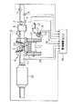
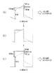
図1は、本実施の形態に係る空燃比制御装置を備えた自動車のエンジンシステムを示す概略構成図である。
このシステムにあって、エンジン1は、吸気系2と、燃焼室3と、排気系4とに大別される。
【0031】
このうち吸気系2は、その上流より、エアクリーナ(図示せず)、スロットルバルブ5、及びサージタンク6を有して構成され、またその各部には、吸気量センサ7、スロットルポジションセンサ(開度センサ)8、及び吸気温センサ9等がそれぞれ設けられている。
【0032】
これらセンサのうち、吸気量センサ7は、スロットルバルブ5の上流側に配されて吸入空気の流量(吸気量)Gaを検出するセンサであり、スロットルポジションセンサ(開度センサ)8は、図示しないアクセルペダルの踏み込み操作に基づき開閉されるスロットルバルブ5の開度情報を出力する。また、吸気温センサ9は、エンジン1に吸入される空気の温度(吸気温)THAを検出するセンサである。
【0033】
また、この吸気系2には、燃料噴射弁10が設けられている。図示しない燃料タンクから圧送される燃料は、該燃料噴射弁10の操作に応じてエンジン1内に噴射供給され、同吸気系2を通じて吸入される空気と混合される。
【0034】
他方、排気系4は、触媒(三元触媒)20、及び酸素センサ11を備えて構成される。触媒20は、燃焼室3から排出される排気中に含まれる一酸化炭素(CO)、炭化水素(HC)、及び酸化窒素(NOx)を浄化するために設けられる。酸素センサ11はこの触媒20の上流に設けられ、触媒通過前における排気中の酸素濃度を検出する。
【0035】
その他、同エンジン1には、点火装置であるイグナイタ12、分配器であるディストリビュータ13が設けられ、その分配された点火電圧が、各気筒の燃焼室3に設けられた点火プラグ14に印加されるようになっている。
【0036】
また、上記ディストリビュータ13には回転数センサ15及び気筒判別センサ16が設けられ、これらセンサ15及び16を通じて、当該エンジン1のエンジン回転数NEが検出され、また燃焼気筒が判別される。
【0037】
また、同エンジン1は、そのシリンダブロック1a内を循環する冷却水によって冷却されるようになっており、その冷却水の水温が、同シリンダブロック1aに設けられた水温センサ17によって検出されるようになる。
【0038】
こうしたエンジンシステムにおいて、上述した各センサの出力は、エンジン1の制御系としての役割を司どる電子制御装置(以下、ECUという)30に対し入力される。
【0039】
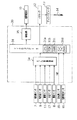
図2は、このECU30のハードウエア構成についてその概要を示したものであり、次に、この図2を併せ参照して、同ECU30の内部構成を説明する。
同図2に示すように、ECU30は、CPU31a、ROM31b、RAM31c、及びバックアップRAM31d等を内蔵したマイクロコンピュータ31を中心に構成される。
【0040】
このマイクロコンピュータ31の入力ポートには、回転数センサ15、気筒判別センサ16、をはじめ、A/D変換回路34を介して、吸気量センサ7、吸気温センサ9、水温センサ17、スロットルポジションセンサ(開度センサ)8、及び酸素センサ11等のアナログ信号を出力するセンサが接続されている。また、同マイクロコンピュータ31の出力ポートには、イグナイタ12や燃料噴射弁10を駆動する駆動回路35等が接続されている。ECU30は、こうしてマイクロコンピュータ31に取り込まれる各センサの出力に基づいて、エンジン1の燃料噴射や点火にかかる各種制御を実行する。
【0041】
次に、上記ECU30が実行する各種制御のうち、空燃比制御についてその概要を説明する。
ECU30は、エンジン1の燃焼に関わる混合気中の空燃比(以下、単に空燃比という)A/Fが同エンジン1の運転状態に適した目標空燃比となるように、燃料噴射弁10から噴射される燃料量を制御制御するための空燃比制御を実行する。この空燃比制御において、ECU30は、吸気量Gaとエンジン回転数NEとに基づき求まる基本燃料噴射量(時間)TAUbsに対し、空燃比フィードバック補正係数FAF及びその他各種制御(例えば、暖機運転時の増量制御や加減速時の増量又は減量制御)によって得られた各種補正係数を加味することにより、最終的な目標燃料噴射量(時間)TAUfを決定する。
【0042】
ここで、本実施形態において採用される空燃比フィードバック補正係数FAFの特性について、酸素センサ11からの検出信号をもとに説明する。
本実施形態では、基本燃料噴射量(時間)TAUbsの補正に用いる空燃比フィードバック補正係数FAFの算出に際し、いわゆる周知の空燃比フィードバック補正係数(本実施形態では基本空燃比フィードバック補正係数という)FAFbsと、見込み空燃比フィードバック補正係数FAFmkという2つの補正係数を併用することとなる。
【0043】
より具体的には、ECU30による毎回のルーチン処理で両補正係数FAFbs及びFAFmkを各々別途に算出しつつ、これら両補正係数のうち何れか一方を各回のルーチン毎に選択して、これを空燃比フィードバック補正係数FAFとして用いることとする。
【0044】
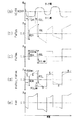
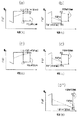
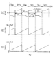
例えば、図3は、酸素センサ11からの検出信号(センサ電圧)VO、該センサ電圧VOに基づいて算出される基本空燃比フィードバック補正係数FAFbs、見込み空燃比フィードバック補正係数FAFmk、及び空燃比フィードバック補正係数FAFに係るそれぞれの信号波形若しくは制御波形を示すタイムチャートである。なお、同図3(a)〜(e)において、時間軸としての横軸は全て同一スケールとなっている。
【0045】
先ず、図3(a)には、酸素センサ11からの検出信号であるセンサ電圧VOの信号波形を示す。酸素センサ11は、エンジン1の空燃比A/Fが理論空燃比に合致する際にはそのセンサ電圧VOが基準電圧KOXR(例えば0.45ボルト(V))となるよう設定されている。そして、空燃比A/Fが理論空燃比より小さいとき(リッチ側)にはセンサ電圧VOが同基準電圧を上回り、理論空燃比より大きいとき(リーン側)にはセンサ電圧VOが同基準電圧以下となる。そこでECU30は、当該電圧VOが基準電圧KOXRを上回り、所定の遅延時間(TDL)が経過した後、空燃比A/Fがリッチ側にあると判断し、基準電圧KOXR以下となり、所定の遅延時間(TDR)が経過した後、空燃比A/Fがリーン側にあると判断する。空燃比フィードバック制御中においては、空燃比A/Fを理論空燃比に収束させるべく、後述する空燃比フィードバック補正係数FAFを変更して目標燃料噴射量(時間)TAUfの増量補正と減量補正とを繰り返す。このため、同図3(a)に示すように、センサ電圧VOもまた、基準電圧KOXRの上下に変動を繰り返すこととなる。
【0046】
次に、図3(b)には、基本空燃比フィードバック補正係数FAFbsの波形(破線)を示す。この基本空燃比フィードバック補正係数FAFbsは、燃料噴射量(時間)TAUbsを補正すべく、前記センサ電圧VOに基づくECU30の判断(リッチ側又はリーン側)を逐次フィードバックするとともに、吸気量Ga等の運転状態を合わせ参照して算出される補正量である。基本的には、空燃比A/Fがリッチ側にあるとECU30が判断している期間中は、目標燃料噴射量(時間)TAUfを減量補正すべく基本空燃比フィードバック補正係数FAFbsを1より小さくし(以下、減量という)、空燃比A/Fがリーン側にあると判断している期間中は、燃料噴射量(時間)TAUfを増量補正すべく当該補正係数FAFbsを1より大きくする(以下、増量という)。
【0047】
ここで、例えば、前記ECU30の判断がリーン側からリッチ側に反転した場合、基本空燃比フィードバック補正係数FAFbsは増量から減量に所定の比例定数RSLをもってスキップ(リーンスキップ)し、その後、ECU30の判断がリッチ側からリーン側に反転するまでは、更に減量側に向かい徐変される。すなわち積分制御が実行される。一方、ECU30の判断がリッチ側からリーン側に反転した場合には、同補正係数FAFbsは減量から増量に所定量RSR分スキップ(リッチスキップ)した後、ECU30の判断が反転するまでは、更に増量側に向かって徐変されることとなる。
【0048】
図3(c)には、見込み空燃比フィードバック補正係数FAFmkの波形(一点鎖線)を示す。見込み空燃比フィードバック補正係数FAFmkは、前記基本空燃比フィードバック補正係数FAFbsがスキップを行う毎に、当該補正係数FAFbsを基準値として更新されることを前提とする。その算出に際しては、同図3(c)に示すように、スキップ時の基本空燃比フィードバック補正係数FAFに対し、見込みスキップ量RSRmk又は見込みスキップ量RSLmkを加味する。そしてその更新値(FAFmk)は、次回のスキップまで保持されることとなる。
【0049】
図3(d)には、前記基本空燃比フィードバック補正係数FAFbsの波形(破線)と、見込み空燃比フィードバック補正係数FAFmkの波形(一点鎖線)を、同一スケールの時間軸(横軸)及び制御量(縦軸)上に重ね合わせて示したものである。
【0050】
同図3(d)に示すように、両補正係数FAFbs及びFAFmkは、同一タイミングでリッチスキップ及びリーンスキップを行うこととなる。そして、例えばリッチスキップ時には、見込み空燃比フィードバック補正係数FAFmkの方が、見込みスキップ量RSRmkの分だけ基本空燃比フィードバック補正係数FAFbsを上回っている。その後の積分制御期間において、基本空燃比フィードバック補正係数FAFbsは徐々に増大するが、見込み空燃比フィードバック補正係数FAFmkは一定の値を保持する。このため、所定時間経過後、点A以降は、基本空燃比フィードバック補正係数FAFbsが見込み空燃比フィードバック補正係数FAFmkを上回ることとなる。
【0051】
一方、リーンスキップ時においては、見込み空燃比フィードバック補正係数FAFmkが見込みスキップ量RSLmkの分だけ基本空燃比フィードバック補正係数FAFbsを下回っている。その後の積分制御期間においては、基本空燃比フィードバック補正係数FAFbsは徐々に減少するが、見込み空燃比フィードバック補正係数FAFmkは一定の値を保持することとなる。このため、所定時間経過後、点B以降は、基本空燃比フィードバック補正係数FAFbsが見込み空燃比フィードバック補正係数FAFmkを下回ることとなる。
【0052】
ここで、ECU30は、基本空燃比フィードバック補正係数FAFbs及び見込み空燃比フィードバック補正係数FAFmkのうち、リッチスキップからリーンスキップまでの期間には両補正係数FAFbs及びFAFmkのうち数値の大きな方を選択し、リーンスキップからリッチスキップまでの期間には数値の小さな方を選択して、これを空燃比フィードバック補正係数FAFとして燃料噴射量(時間)TAUbsの補正を実行する。すなわち、ECU30の決定する空燃比フィードバック補正係数FAFは、結果的に図3(e)に示すような制御波形を形成することとなる。
【0053】
なお、基本燃料噴射量(時間)TAUbsを補正して目標燃料噴射量(時間)TAUfを算出する際、空燃比フィードバック補正係数FAFは、例えば以下に示すような演算中で用いられる。
TAUf = TAUbs×FAF×k1×k2×…×kn…(1)
ただし、k1〜knは、例えば暖機増量、加減速、出力増量等の各種運転状態を考量した補正係数であり、図示しない処理ルーチンにおいて別途算出されるものである。
【0054】
以下、上述したフィードバック補正係数FAFを用いて行う本実施形態に係る空燃比制御について詳述する
先ず、本実施形態に係る一連の空燃比制御について、その概要を説明する。
【0055】
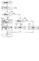
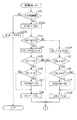
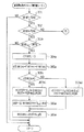
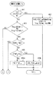
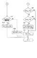
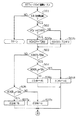
図4に示すフローチャートは、本実施形態に係る空燃比制御を実行するメインルーチンであって、特にフィードバック補正係数FAFの算出に関わる制御手順を総括的に示したものである。本ルーチンは、ECU30により所定時間毎に実行される。
【0056】
同図に示すように、本実施形態にあって、空燃比フィードバック補正係数の算出に係る制御は、大きくは、ステップ001の条件設定ルーチン、ステップ002及びステップ005の触媒床温判定ステップ、ステップ003の空燃比フィードバック補正係数算出ルーチン、ステップ004の応答遅れ及びスキップ量学習ルーチン、ステップ006のホールド制御ルーチン、並びにステップ007のオープン制御ルーチンを通じて行われる。
【0057】
本ルーチンに処理が移行すると、ECU30は、先ずステップ001の条件設定ルーチンにおいて、酸素センサ11からのセンサ電圧VOに基づき現在の空燃比に係る情報を後述するリッチ判定フラグXOXR、スキップタイミングフラグXRQSKPのフラグ状態(設定又は設定解除)として記憶する。これらの情報は、続く各制御ルーチンにおいて参照されることとなる。
【0058】
次に、ECU30はステップ002において、触媒20の温度を模擬床温として推定し、この推定温度が所定温度Tcより下回っていればステップ003〜004に係る空燃比フィードバック制御を実行する。一方当該推定温度が所定温度Tc以上であれば、さらにステップ005において、同推定温度が所定温度td(但し、td>tc)以上であるか否かを判断する。ステップ005における判断が否定であればステップ006に係るホールド制御を実行し、同ステップ005における判断が肯定であれば、フィードバック制御を停止し、オープン制御(燃料噴射量の増大)を行う。なお、触媒20の模擬床温推定にあたっては、エンジン回転数NE等のエンジン負荷に関わるパラメータや車速等に基づき昇温速度を推定して行う。
【0059】
ステップ003〜004に係る一連の空燃比フィードバック制御においては、基本的には図3で説明した波形を採用した空燃比フィードバック補正係数FAFの算出(ステップ003)を行い、続いて同空燃比フィードバック制御に係る応答遅れ量及びスキップ量の学習制御(ステップ004)を行って、当該メインルーチンに係る一連の処理を一旦終了する。
【0060】
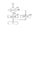
次に、上記各ステップ001〜005での具体的な処理内容について順次説明する。
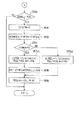
図5には、前記メインルーチン(図4参照)を構成する各制御ルーチンのうち、現在の運転状態が空燃比フィードバック制御に適合した状態にあるか否かを判断するとともに、酸素センサ11からのセンサ電圧に基づいて、空燃比制御に必要な情報を記憶・更新するための「条件設定ルーチン」(図4中ではステップ001)の処理内容を示す。
【0061】
処理がこのルーチンに移行すると、ECU30は先ずステップ101において、空燃比フィードバック制御を実行するための諸条件(a1)〜(a5)が満たされているか否かを判断する。
(a1)始動時でないこと。
(a2)燃料カット中ではないこと。
(a3)冷却水温THWが所定温度以上であること。
(a4)酸素センサ11が活性化状態であること。
(a5)エンジンが高負荷又は高回転状態でないこと。
(a6)触媒床温が所定温度td未満であること。
そして、上記諸条件(a1)〜(a6)が全て満たされているときには、現在の運転状態が空燃比フィードバック制御を行うための条件に適合していると判断して、処理をステップ102aに移行する。一方、上記条件のうち何れか一つでも満たされていなければ、現在の運転状態は空燃比フィードバック制御を行うための条件に適合していないと判断し、処理をステップ102bに移行する。
【0062】
ステップ102aにおいては、空燃比フィードバック制御許可フラグ(以下、F/B許可フラグという)XFAFを「オン(ON)」に設定し、処理をステップ103に移行する。一方、ステップ102bにおいては、F/B許可フラグを「オフ(OFF)」に設定し、本ルーチンを一旦抜ける。
【0063】
ステップ103においては、今回読み込まれた酸素センサ11からのセンサ電圧VOiが、基準電圧KOXRを上回っているか否かを判断する。そして、その判断が肯定であれば処理をステップ104に移行し、その判断が否定であれば処理をステップ114に移行する。
【0064】
一連のステップ104〜108においては、センサ電圧VOが基準電圧KOXR以下であるとの判断が先のステップ103にて連続してなされることを条件に、その連続回数を計測して、その回数が所定回数以上に達したときにリッチ判定フラグXOXRを「ON」に設定する処理、すなわちセンサ電圧VOのノイズによる誤検出を減らして空燃比フィードバック補正係数FAFの制御波形の安定化を図るための遅延処理を行う。ここでリッチ判定フラグXOXRとは、空燃比フィードバック補正係数FAFを更新する際、同補正係数FAFを増量するのか、或いは減量するのかを選択するための基準として用いるフラグであって、空燃比A/Fは現在リッチ側にあると判断されたときには「ON」に設定され、リーン側にあると判断されたときには「OFF」に設定解除されるものである。
【0065】
すなわちECU30は、先ずステップ104において、回数計測用ディレイカウンタのカウント値(以下、単にディレイカウンタという)CDLYをディクリメントする。
【0066】
続くステップ105においては、ディレイカウンタが基準値「0」以下であるか否かを判断する。そしてその判断が肯定であれば、処理をステップ106に移行し、その判断が否定であれば処理をステップ120に移行する。
【0067】
ステップ106においては、ディレイカウンタCDLYが基準値「0」であるか否かを判断する。そしてその判断が肯定であれば処理をステップ107に移行し、同ステップ107においては、スキップ制御を実行すべきタイミングであることを認識するためのスキップタイミングフラグXRQSKPを「ON」に設定し、処理をステップ108に移行する。また、先のステップ106での判断が否定であれば処理をステップ108にジャンプする。
【0068】
ステップ108においては、ディレイカウンタCDLYに所定のリーン側遅延処理値TDLに負の符号を付した値「−TDL」を設定し、処理をステップ120に移行する。
【0069】
一方、先のステップ103を経た後、処理をステップ110に移行した場合には、続く一連のステップ114〜118を実行する。これらステップ114〜118においては、センサ電圧VOが基準電圧KOXR以下であるという判断が先のステップ103にて連続してなされることを条件に、その連続回数を計測して、その回数が所定回数以上に達したときにリッチ判定フラグXOXRを「ON」に設定する処理、すなわちセンサ電圧VOのノイズによる誤検出を減らして空燃比フィードバック補正係数FAFの制御波形の安定化を図るための遅延処理を行う。
【0070】
すなわちECU30は、先ずステップ114において、回数計測用ディレイカウンタのカウント値(以下、単にディレイカウンタという)CDLYをインクリメントする。
【0071】
続くステップ115においては、ディレイカウンタが基準値「0」以上であるか否かを判断する。そしてその判断が肯定であれば、処理をステップ116に移行し、その判断が否定であれば処理をステップ120に移行する。
【0072】
ステップ116においては、ディレイカウンタCDLYが基準値「0」であるか否かを判断する。そしてその判断が肯定であれば処理をステップ117に移行し、同ステップ117においては、スキップ制御を実行すべきタイミングであることを認識するためのスキップタイミングフラグXRQSKPを「ON」に設定し、処理をステップ118に移行する。また、先のステップ116での判断が否定であれば処理をステップ118にジャンプする。
【0073】
ステップ118においては、ディレイカウンタCDLYに所定のリッチ側遅延処理値TDRを設定し、処理をステップ120(図5)に移行する。
ステップ120においては、ディレイカウンタCDLYが基準値「0」を下回っているか否かを判断する。そしてその判断が肯定であれば処理をステップ121に移行し、その判断が否定であれば処理をステップ122に移行する。
【0074】
ステップ121においてはリッチ判定フラグXOXRを「ON」に設定する。また、ステップ122においては同リッチ判定フラグXOXRを「OFF]に設定解除する。
【0075】
そして、上記ステップ121又はステップ122のうち何れかを経た後、ECU30はその後の処理を一旦終了する。
ちなみに、前記スキップタイミングフラグXRQSKPのクリア(「OFF」)は、後述する「フィードバック補正係数算出ルーチン」にて行う。
【0076】
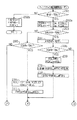
次に、図4において説明した空燃比制御に係る一連のサブルーチンのうち、空燃比フィードバック補正係数FAFを算出すべく実行されるステップ003の空燃比フィードバック補正係数算出ルーチンについてその処理内容の詳細を説明する。
【0077】
図7及び図8には、上記空燃比フィードバック補正係数算出ルーチンに係る処理手順のフローチャートを示す。
処理がこのルーチンに移行すると、ECU30は先ずステップ201において、図5のステップ101及びステップ102a,102bで説明したF/B許可フラグXFAFが「ON」に設定されているか否かを判断する。そして、F/B許可フラグXFAFが「ON」に設定されていれば処理をステップ202aに移行し、F/B許可フラグが「OFF」に設定解除されていれば、その処理をステップ202bに移行する。ステップ202bにおいては、以下の(b1)〜(b3)に示す態様で、基本空燃比フィードバック補正係数FAFbs及び見込み空燃比フィードバック補正係数FAFmk、並びに空燃比フィードバック補正係数FAFの初期化を行う。
(b1)FAFbs=1
(b2)FAFmk=1
(b3)FAF =1
そしてECU30は、その後の処理を一旦終了する。
【0078】
一方、ステップ202aにおいては、リッチ側見込みスキップ量RSRmk及びリーン側見込みスキップ量RSLmkを算出する。両見込みスキップ量の算出に際しては、ECU30は、先ずアイドル認識フラグXIDLEの設定状態を認識する。アイドル認識フラグXIDLEは、前記エンジン1がアイドル状態にあるときには「ON」に設定され、通常の運転状態にあるときには「OFF」に設定解除される。そこでECU30は、アイドル認識フラグXIDLEの設定状態に対応して予め設定されたマップ等を参照し、見込みスキップ量RSRmk及びRSLmkをそれぞれ吸気量Gaに基づいて算出する。ちなみに、両見込みスキップ量RSRmk及びRSLmkは、アイドル認識フラグXIDLEが「OFF」である場合に比し、「ON」である場合により大きな値となる傾向にある。また、吸気量Gaが増大した場合にも、より大きな値として算出される傾向にある。
【0079】
続くステップ203においては、図5及び図6において説明したスキップタイミングフラグXRQSKPが「ON」に設定されているか否かを判断する。そして、スキップタイミングフラグXRQSKPが「ON」に設定解除されていると判断した場合には、処理をステップ204に移行し、スキップタイミングフラグXRQSKPが「OFF」に設定されている場合には処理をステップ205に移行する。
【0080】
ステップ204においては、現在「ON」に設定されているスキップタイミングフラグXRQSKPを「OFF」に設定解除する。
続くステップ206以降は、スキップ制御に係る処理を行う。すなわち、先ずステップ206においては、リッチ判定フラグXOXRの設定状態についての判断を行う。そして、その設定状態が「ON」であれば処理をステップ230に移行し、設定状態が「OFF」であれば処理をステップ240に移行する。
【0081】
ステップ230においては、リッチ判定フラグXOXR及びアイドル認識フラグXIDLEの設定状態に対応して予め設定されたマップを参照し、吸気量Gaに基づいて、リーン側スキップ量RSLを算出する。さらに、こうして算出されたリーン側スキップ量RSLに負の符号を付して、空燃比フィードバック補正係数FAFの今回の更新量RSKiとして一時記憶する。
【0082】
続くステップ231においては、前回の基本空燃比フィードバック補正係数FAFbsi-1に更新量RSKiを加算し、さらにリーン側見込みスキップ量RSLmkを減算して今回の見込み空燃比フィードバック補正係数FAFmkとする。
【0083】
さらに続くステップ232においては、前回の基本空燃比フィードバック補正係数FAFbsi-1に更新量RSKiを加算して今回の基本空燃比フィードバック補正係数FAFbsとする。
【0084】
一方、先のステップ206における判断が否定であり、処理をステップ240に移行した場合には、同ステップ240(図8)において、リッチ判定フラグXOXR及びアイドル認識フラグXIDLEの設定状態に対応して予め設定されたマップを参照し、吸気量Gaに基づいて、リッチ側スキップ量RSRを算出する。さらに、こうして算出されたリッチ側スキップ量RSRを空燃比フィードバック補正係数FAFの今回の更新量RSKiとして一時記憶する。
【0085】
続くステップ241においては、前回の基本空燃比フィードバック補正係数FAFbsi-1に更新量RSKiを加算し、さらにリッチ側見込みスキップ量RSRmkを加算して今回の見込み空燃比フィードバック補正係数FAFmkとする。
【0086】
さらに続くステップ242においては、前回の基本空燃比フィードバック補正係数FAFbsi-1に更新量RSKiを加算して今回の基本空燃比フィードバック補正係数FAFbsとする。
【0087】
ステップ205以降では、空燃比フィードバック補正係数FAFを徐変させるための積分制御に係る処理を行う。すなわち、先ずステップ205においては、リッチ判定フラグXOXRの設定状態についての判断を行う。そして、その設定状態が「ON」であれば処理をステップ210に移行し、その設定状態が「OFF」であれば処理をステップ220(図8)に移行する。
【0088】
ステップ210においては、リッチ判定フラグXOXR及びアイドル認識フラグXIDLEの設定状態に対応して予め設定されたマップを参照し、吸気量Gaに基づいて、リーン側積分量KiLを算出する。さらに、こうして算出されたリーン側積分量KiLに負の符号を付して、空燃比フィードバック補正係数FAFの今回の更新量RSKiとして一時記憶する。
【0089】
続くステップ211においては、前回の基本空燃比フィードバック補正係数FAFbsi-1に更新量RSKiを加算して今回の基本空燃比フィードバック補正係数FAFbsとする。
【0090】
一方、先のステップ205における判断が否定であり処理をステップ2220に移行した場合には、同ステップ220において、リッチ判定フラグXOXR及びアイドル認識フラグXIDLEの設定状態に対応して予め設定されたマップを参照し、吸気量Gaに基づいて、リッチ側積分量KiRを算出する。さらに、こうして算出されたリッチ側積分量KiRを、空燃比フィードバック補正係数FAFの今回の更新量RSKiとして一時記憶する。
【0091】
続くステップ221においては、前回の基本空燃比フィードバック補正係数FAFbsi-1に更新量RSKiを加算して今回の基本空燃比フィードバック補正係数FAFbsとする。
【0092】
上記ステップ211(図7)、221(図8)、232(図7)、242(図8)のうち、ステップ221又はステップ242を経た後は、処理をステップ250(図8)に移行する。他方、ステップ211又はステップ232を経た後は、処理をステップ260(図8)に移行する。
【0093】
ところで、上記ステップ230→231→232(以下、処理手順1という)、及びステップ240→241→242(以下、処理手順2という)に係るスキップ制御のための一連の処理のうち、ステップ231及びステップ242で算出される見込み空燃比フィードバック補正係数FAFmkは、それぞれ前回の基本空燃比フィードバック補正係数FAFbsi-1を基準値として、更新量RSKi及び見込みスキップ量RSRmk,RSLmkを加味して求めることとしている。
【0094】
また、処理手順1で算出される見込み空燃比フィードバック補正係数FAFmkは、同処理手順1で算出される基本空燃比フィードバック補正係数FAFbsより小さな値をとる一方、処理手順2で算出される見込み空燃比フィードバック補正係数FAFmkは、同処理手順2で算出される基本空燃比フィードバック補正係数FAFbsより大きな値をとることがフローチャートから明らかである。
【0095】
そして、後続のステップ250及びステップ260(図8)のうち何れのステップでの判断を経た後も、処理をステップ251に移行することとなる。結局、スキップ後の空燃比フィードバック補正係数FAFとしては見込み空燃比フィードバック補正係数FAFmkが常時適用されることとなる。すなわち実質的には、スキップ制御後の空燃比フィードバック補正係数FAFは、スキップタイミング直前にある基本空燃比フィー祖バック補正係数FAFbsに対し、更新量RSKi(RSR又は−RSL)を加算し、更にリッチ側見込みスキップ量RSRmkを加算、或いはリーン側見込みスキップ量RSLmkを減算して求めることとなる。
【0096】
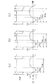
例えば、図9(a)及び(b)には、本実施形態に係る空燃比フィードバック制御でのスキップ制御に係る空燃比フィードバック補正係数FAFの変化態様の一例をタイムチャート上に示す。
【0097】
先ず同図9(a)に示すように、リーンスキップ時には、空燃比フィードバック補正係数FAFが、点L1から点L2、すなわちスキップ直前の基本空燃比フィードバック補正係数FAFbsに対して所定量(RSL+RSLmk)を減算した値まで移行する。
【0098】
また同図9(b)に示すように、リッチスキップ時には、空燃比フィードバック補正係数FAFが、点R1から点R2、すなわちスキップ直前の基本空燃比フィードバック補正係数FAFbsに対して所定量(RSR+RSRmk)を加算した値まで移行する。
【0099】
このようなスキップ制御時における空燃比フィードバック補正係数FAFの移行態様は、以下の理由により適用するものである。
空燃比フィードバック制御を行うに際し、酸素センサによるセンサ電圧VOの変動周期、すなわちセンサ電圧VOがリーンからリッチに反転してから次回リーンからリッチに反転するまで、或いはリッチからリーンに反転してから次回リッチからリーンに反転するまでの長さは、排気の流速(吸気量Ga)、燃焼室から酸素センサまでの距離、排気通路の構造、酸素センサ自身の応答性等によって異なる。
【0100】
他方、実際の空燃比A/FとECUに認識されるセンサ電圧VOとの間には、条件設定ルーチン(図5及び図6)で説明した遅延処理時間も含めて、酸素センサの応答遅れ等により生じる時間遅れ(変動周期の位相差)が存在することが広く知られている。
【0101】
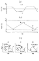
例えば、図10(a)及び(b)には、それぞれ実際の空燃比A/F及びセンサ電圧VOを同一時間軸上に示すものである。
同図10(a)及び(b)に示すように、空燃比A/Fの挙動に対するセンサ電圧VOの時間遅れは、リーンからリッチへの反転に係るもの(リッチ側時間遅れΔTLR)よりリッチからリーンへの反転に係るもの(リーン側時間遅れΔTRL)の方が長いことが公知である。また、これら時間遅れΔTRL及びΔTLRは、先述したセンサ電圧VOの変動周期が短い場合ほど短く、同変動周期が長いほど長くなる傾向が強い。
【0102】
このため、センサ電圧VOの変動周期の長い制御系では、リーン側時間遅れとリッチ側時間遅れとの差(ΔTLR−ΔTRL)が拡大する。すなわち、実際の空燃比A/Fの変動に対し、センサ電圧VOは速やかにリッチ側へ反転する一方、リーン側への反転はもたつく傾向が強まり、結果として空燃比A/Fがリーン側に偏在する傾向が増す。これとは反対に、センサ電圧VOの変動周期の短い制御系では、空燃比A/Fが相対的にリッチ側へ偏在する傾向が増す。
【0103】
この点、上記図9(a)及び(b)に示した態様でスキップ制御を行うようにすれば、空燃比フィードバック補正係数FAFの振幅が縮小し、制御周波数が高まるとともに、当然上記のようなリーン側時間遅れとリッチ側時間遅れとの差(ΔTLR−ΔTRL)の拡大も抑制できることとなり、空燃比A/Fを緻密に目標値へ収束させることができるようになる。
【0104】
すなわち本実施形態では、上記のような処理手順を用いることにより、リーン側へのスキップ量(RSL+RSLmk)の減算或いはリッチ側へのスキップ量(RSR+RSRmk)の加算の基準点を変更することにより、空燃比フィードバック補正係数FAFの制御波形の振幅の減少と周波数の増大とを図り、センサ電圧VOの変動周期に起因する空燃比のリッチずれ又はリーンずれを好適に抑制する。
【0105】
また、実際の目標空燃比とスキップ後のFAFとの公差を一定に維持するという趣旨により、以下に説明するような他の態様(第2の態様という)で、スキップ制御に係る空燃比フィードバック補正係数の算出態様を構成してもよい。
【0106】
すなわち、図9(c)及び(d)には、本発明に係る空燃比フィードバック制御のうち、スキップ制御に係る他の態様を空燃比フィードバック補正係数FAFの変化態様としてタイムチャート上に示す。
【0107】
先ず、同図9(c)に示すように、リーンスキップ時に空燃比フィードバック補正係数FAFが点L1から点L2、すなわちスキップ直前の基本空燃比フィードバック補正係数FAFbsを基準値として、所定量(RSL+RSLmk)を減算した値まで移行することは、図9(a)に示した態様と同様である。
【0108】
ただし第2の態様では、リッチスキップ時には、同図9(b)に示すように、空燃比フィードバック補正係数FAFが点R1から点R2まで移行する際、スキップ直前の空燃比フィードバック補正係数FAF(FAFmk)を基準値として、所定量(RSR+RSRmk)を加算した値まで移行することとする。ただし、図9(d’)に示すように、リッチスキップ時において、基本空燃比フィードバック補正係数FAFbsが見込み空燃比フィードバック補正係数FAFmkを横切った後にスキップ制御を行う場合には、基本空燃比フィードバック補正係数FAFbsを基準値として、所定量(RSR+RSRmk)を加算した値まで、スキップ後の空燃比フィードバック補正係数FAFを移行させる構成とする。すなわち第2の態様では、リッチスキップ時には、スキップ直前に適用されている空燃比フィードバック補正係数FAFを基準値としてスキップ制御を行うよう制御を構成する。
【0109】
このような第2の態様によれば、図9(c)の態様を適用することにより、センサ電圧VOの反転周期が短い酸素センサを用いる場合ほど空燃比A/Fがリッチずれし易いという傾向を抑制することとなり、さらに図9(d)及び(d’)の態様を適用することにより、これもセンサ電圧VOの反転周期が短い酸素センサを用いる場合ほど空燃比A/Fがリッチずれし易いという傾向が十分抑制されることとなって、酸素センサからのセンサ電圧の反転周期がばらついても、目標空燃比とスキップ後の空燃比フィードバック補正係数FAFとの公差ばらつきが好適に抑制される。
【0110】
さて、図7及び図8に示す「フィードバック補正係数算出ルーチン」において、上記ステップ221(図8)又はステップ242(図8)を経てステップ250(図8)に処理を移行した場合、同ステップ250においては、今回算出した基本空燃比フィードバック補正係数FAFbsが、見込み空燃比フィードバック補正係数FAFmkを下回っているか否かを判断する。そして、同ステップ250における判断が肯定である場合には処理をステップ251に移行し、その判断が否定である場合には処理をステップ261に移行する。
【0111】
一方、先のステップ211(図7)又はステップ232(図7)を経て処理をステップ260(図8)に移行した場合、同ステップ260においては、今回算出した基本空燃比フィードバック補正係数FAFbsが、見込みフィードバック補正係数FAFmk以上であるか否かを判断する。そして、同ステップ260における判断が肯定である場合には処理をステップ251に移行し、その判断が否定である場合には処理をステップ261に移行する。
【0112】
最後にECU30は、処理をステップ251に移行した場合には、見込み空燃比フィードバック補正係数FAFmkを今回の空燃比フィードバック補正係数FAFとして採用する。一方、処理をステップ261に移行した場合には、基本空燃比フィードバック補正係数FAFbsを今回の空燃比フィードバック補正係数FAFとして採用する。そして、いずれの場合にもその後の処理を一旦終了する。
【0113】
ECU30は、以上説明した「空燃比フィードバック補正係数算出ルーチン」の処理手順に従い、本実施形態において採用される空燃比フィードバック補正係数FAFの算出を行う。
【0114】
すなわち、ECU30が毎回の処理で算出する基本空燃比フィードバック補正係数FAFbs及び見込みフィードバック補正係数FAFmkは、いずれも酸素センサ11からのセンサ電圧VOに基づく空燃比A/F情報に対応してリッチスキップ、積分制御、リーンスキップ、積分制御を繰り返すフィードバック制御量であり、上記処理ルーチン中では以下に示す式に基づいてその値を更新していく。

【0115】
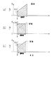
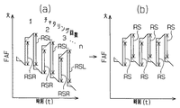
図11には、空燃比フィードバック制御に係る空燃比フィードバック補正係数FAFの制御波形のうち、リッチスキップからリーンスキップに至る一期間にかかるものを一例として示す。なお、図11(a)には従来の空燃比フィードバック制御にかかる制御波形、図11(b)には制御波形を矩形としたもの、そして図11(c)には本実施形態で採用された制御波形を示す。また、各図11(a)〜(c)に示す制御波形をもって得られる面積(斜線部)は全て同一であり、このことは、燃料噴射量TAUの総補正量(増量)はほぼ同等であることを意味する。
【0116】
各図11(a)〜(c)を比較して明らかなように、従来の制御波形(図11(a))を採用する空燃比フィードバック補正係数FAFの振幅が三者中最も大きく、制御時間も最長となる。
【0117】
そこで、空燃比フィードバック補正係数FAFの振幅の最小化を図りつつ制御時間も最短とするためには、矩形の制御波形(図11(b))を採用するのが最も好ましいとも考えられる。
【0118】
ところが、矩形の制御波形を採用すると、予め的確なスキップ量の設定が行われなければ、その周波数に変動を生じやすいという問題がある。これは、積分制御中に空燃比フィードバック補正係数FAFを徐変させないため制御時間が容易に伸縮してしまうためである。このような制御時間変動の生じ易さは、エンジン1の吸気量Ga等の変化量が大きくなる過渡的な運転状態においてとくに顕著となる。このように、FAFの制御時間及びその変動は、それぞれ制御周波数及びその乱れを反映するようになる。さらに、矩形の制御波形を採用した場合には、スキップ制御後の空燃比フィードバック補正係数FAFがストイキを横切ることができなければ、フィードバック制御が停止してしまうこととなる。
【0119】
この点、本実施形態における空燃比フィードバック補正係数FAFの制御波形(図11(c))によれば、その周波数を高めつつ振幅も抑制することができ、ひいては緻密且つ応答性の高い空燃比フィードバック制御を行うことができるようになる。これにより、トルク変動の抑制やドライバビリティも向上し、排気特性もその最適化が図られる。
【0120】
また、上記「空燃比フィードバック補正係数算出ルーチン」についての説明から明らかなように、空燃比フィードバック補正係数FAFの制御波形は、スキップ量RSR及びRSL、見込みスキップ量RSRmk及びRSL、並びに積分量KiR及びKiLからなる構成要素により決定されることとなる。すなわち、これら制御量を各々変更することにより、制御波形を非対称化したり、空燃比フィードバック補正係数FAFの制御中心(基本的には「1」)をリッチ側やリーン側に修正したりすること等も容易となる。
【0121】
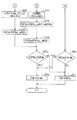
次に、図4において説明した空燃比フィードバック制御に係る一連のルーチンのうち、ステップ004の応答遅れ及びスキップ量学習ルーチンについてその処理内容の詳細を説明する。
【0122】
図3(a)〜図3(e)において説明したように、本実施形態による空燃比フィードバック制御では、空燃比フィードバック補正係数FAFをリーンスキップ、若しくはリッチスキップさせた後の積分制御期間においては、所定時間一定量に保持し、その後更に徐変することとしている。この結果として形成される空燃比フィードバック補正係数FAFの制御波形は、同図3(e)に示した通りである。
【0123】
そこで、この応答遅れ及びスキップ量学習ルーチンは、前記「空燃比フィードバック補正係数算出ルーチン」において逐次算出される空燃比フィードバック補正係数FAFの波形をさらに最適化するためのものであり、具体的には、当該波形に係る周波数の増大と振幅の抑制とを併せ図るとともに、吸気量Gaに基づいて区画した複数の運転領域毎に、当該波形に係る情報、すなわち制御応答遅れdlRSR,dlRSL、スキップ量RSR,RSL、及び見込みスキップ量RSRmk,RSLmkを学習更新するためものである。
【0124】
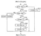
図12及び図13には、上記応答遅れ及びスキップ量学習ルーチンに係る処理手順のフローチャートを示す。
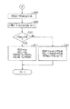
処理がこのルーチンに移行すると、ECU30は先ずステップ301において、F/B許可フラグXFAFが「ON」に設定されているか否かを判断する。そして、その判断が肯定であれば処理をステップ302に移行し、その判断が否定であれば本ルーチンを一旦抜ける。
【0125】
ステップ302においては、リッチ判定フラグXOXRが「ON」に設定されているか否かを判断する。そして、その判断が肯定であれば処理をステップ303aに移行し、その判断が否定であれば処理をステップ303b(図13)に移行する。
【0126】
ステップ303aにおいては、前回の処理においてリッチ判定フラグXOXRが「OFF」に設定解除されていたか否かを判断する。この判断が肯定であれば、前回のルーチンから今回のルーチンに処理が移行する間に空燃比A/Fはリーンからリッチに反転したとみなし、処理をステップ304aに移行する。一方、その判断が否定であれば、ECU30は今回のルーチン処理を一旦終了する。
【0127】
ステップ304aにおいては、リーン側応答遅れカウンタCFAFLを「0」にリセットする。このリーン側応答遅れカウンタCFAFLは、リッチ側応答遅れCFAFRとともに、本ルーチンとは別途のプログラムとして構成される2種のタイマカウンタによって、常時更新され続けるカウント値である。
【0128】
ちなみに図14に示すように、リッチ側応答遅れカウンタCFAFRは所定周期毎にカウントアップしつつ空燃比フィードバック補正係数FAF(図14(a))がリッチスキップする毎にリセットされ(図14(b))、一方リーン側応答遅れカウンタCFAFLは、所定周期毎にカウントアップしつつ空燃比フィードバック補正係数FAF(図14(a))がリーンスキップする毎にリセットされる(図14(c))。
【0129】
続くステップ305aにおいては、先行の処理ルーチンである前記「空燃比フィードバック制御ルーチン」で今回算出された見込み空燃比フィードバック補正係数FAFmk及び基本空燃比フィードバック補正係数FAFbsを用い、以下に示す式(2)に従って両者間の偏差(以下、見込み量−基本量偏差という)dlmkbsを算出する。
dlmkbs=FAFmk−FAFbs…(2)
ここで、この見込み量−基本量偏差dlmkbsは、見込み空燃比フィードバック補正係数FAFmk−基本空燃比フィードバック補正係数FAFbs間偏差であって、特にこの場合は、両補正係数がリーンからリッチへ反転する直前の偏差に相当する。
【0130】
ステップ306aにおいては、前記ステップ305aで算出した見込み量−基本量偏差dlmkbsが0以上であるか否か、言い換えると、見込みフィードバック補正係数FAFmkが基本空燃比フィードバック補正係数FAFbs以上であるか否かを判断する。そして、その判断が肯定であれば処理をステップ307a1に移行し、その判断が否定であれば処理をステップ307a2に移行する。
【0131】
ステップ307a1及びステップ307a2においては、空燃比フィードバック補正係数FAFがリーンからリッチへ反転したときのスキップ量RSRに係る最新の履歴を学習値として更新する。このスキップ量RSRの算出に際しては、先ず前記ステップ305aにおいて算出した見込み量−基本量偏差dlmkbsに基づきスキップ量RSRの変化量dlRSRを演算する。そして、更に当該変化量dlRSRをスキップ量RSRの旧学習値RSRi-1に加算し、この値を最新の学習値とする。この学習値(スキップ量)RSRは、吸気量Gaに基づいて区画された複数の運転領域のうち、現在の運転領域(Ga)に該当する領域に係る学習値として前記バックアップRAM31dに格納されることとなる。そして、ステップ307a1における処理の後にはステップ308aに移行し、ステップ307a2における処理の後にはステップ309aにジャンプする。なお、ステップ307a1における処理で見込み量−基本量偏差dlmkbsに基づいて求められる変化量dlRSRは、リッチ側スキップ量RSRを増量させるための更新量であるのに対し、ステップ307a2における処理で求められる変化量dlRSRは、リッチ側スキップ量RSRを減量させるための更新量である。よってステップ307a1で求められる変化量dlRSRは正の値、ステップ307a2で求められる変化量dlRSRは負の値となる。
【0132】
ステップ308aにおいては、図14(a)に併せ示すように、旧学習値として前記バックアップRAM31dに記憶されているリッチ側応答遅れ時間dtRi-1に対し、現在のリッチ側応答遅れカウンタCFAFRの値(dtRi)を加味した値を、最新の学習値dtRとして同バックアップRAM31dに記憶更新する。なお、図12のフローチャート中のステップ308aに示すように、最新の学習値は、旧学習値dtRi-1とリッチ側応答遅れカウンタCFAFR(dtRi)との平均値として算出するが、学習値の急激な変動を抑制するために、リッチ側応答遅れカウンタCFAFRの最新学習値dtRへの寄与率は小さく設定(1/64なまし(徐変))してある。
【0133】
ステップ309aにおいては、以下に示す式(3)に従って見込みスキップ量RSRmkを算出する。
RSRmk = dtR × KiR…(3)
そして、この見込みスキップ量RSRmkもまた、吸気量Gaに照らした現在の運転領域に係る学習値として前記バックアップRAM31dに格納されることとなる。同ステップ309aにおける処理を経た後、ECU30は今回のルーチンを終了する。
【0134】
上記ステップ301、ステップ302、及びステップ303a〜309aにおける一連の処理では、図14(a)に示す空燃比フィードバック補正係数FAFがリッチスキップをしてからリーンスキップをするまでの間、同空燃比フィードバック補正係数FAFの制御波形を矩形に近似させつつ、当該制御波形にかかる情報を学習値として記憶・更新するためのものである。そして、このような制御波形の最適化処理を繰り返すことにより、記憶される学習値により形成される制御波形は、当該学習制御が行われている運転領域(吸気量Ga)に対応する最適な制御波形に近似されていくこととなる。
【0135】
一方、前記ステップ302における判断が否定であり、処理をステップ303b(図13)に移行した場合のステップ303b〜ステップ309bに示す一連の処理は、同じく図14(a)に示す空燃比フィードバック補正係数FAFがリーンスキップをしてからリッチスキップをするに至るまでの制御波形にかかる情報を学習値として記憶・更新するためのものである。なお、同ステップ303b〜ステップ309bに示す処理は上述したステップ303a〜ステップ309aにおいて行う処理に対応したものであるため、ここでの重複した説明は割愛する。
【0136】
ECU30は、以上説明した「応答遅れ及びスキップ量学習ルーチン」の処理手順に従い、前記「空燃比フィードバック補正係数算出ルーチン」で算出する空燃比フィードバック補正係数FAFの制御波形の最適化を行うとともに、当該最適化された制御波形に係る制御情報の記憶更新を行う。
【0137】
図15は、上記応答遅れ及びスキップ量学習ルーチンにより、空燃比フィードバック補正係数FAFの制御波形がどのような態様で変更されるかを、リッチスキップからリーンスキップに至る一期間を例にとって模式的に示したものである。
【0138】
例えば、同図15(a)に示す制御波形のように、リーンスキップ直前の基本空燃比フィードバック補正係数FAFbsが見込み空燃比フィードバック補正係数FAFmkを上回っている場合には、当該「応答遅れ及びスキップ量学習ルーチン」(図12)は、ステップ306aでの判断をもとに、制御波形を矩形に近似させるべく以下のような手順で処理を行うこととなる。
(A1)次回リッチスキップ時のスキップ量RSRを増量し、学習する(ステップ307a1)。
(A2)当該スキップ量RSRから推定される次回の応答遅れdtRを算出する(ステップ308a)。
(A3)応答遅れdtRに所定の積分量KiRを乗算して次回の見込みスキップ量RSRmkを算出し、学習する(ステップ309a)。
一方、同図15(c)に示す制御波形のように、リーンスキップ直前の基本空燃比フィードバック補正係数FAFbsが見込み空燃比フィードバック補正係数FAFmk以下である場合には、制御波形は矩形となるが、矩形を保持しつつ積分制御時の空燃比フィードバック補正係数FAFを減少させることにより、同空燃比フィードバック補正係数FAFの振幅を抑制し得る。
【0139】
そこで、当該「応答遅れ及びスキップ量学習ルーチン」(図13)では、以下のような手順に従い、当該振幅の抑制を図る。
(C1)次回リッチスキップ時のスキップ量RSRを減量し、学習する(ステップ307a2)。
(C2)今回の応答遅れdtR(更新せず)に所定の積分量KiRを乗算し、次回の見込みスキップ量RSRmkとして学習する(ステップ309a)。
このような学習ルーチンによる制御の結果、リッチスキップからリーンスキップに至る期間における空燃比フィードバック補正係数FAFの制御波形は、同図15(b)に示すような波形、すなわち略矩形を有しつつ、積分制御期間のうちのリーンスキップ直前の微小期間に、同空燃比フィードバック補正係数FAFの徐変が生じるような波形となる。
【0140】
前記「空燃比フィードバック補正係数算出ルーチン」による空燃比フィードバック制御を実行しつつ、これに上記の「応答遅れ及びスキップ量学習ルーチン」による処理を併用することにより、運転領域(本実施形態にあっては吸気量Gaの領域)を限定した上で最適な制御波形を学習させることができるため、制御波形を矩形に近似させても、過渡的な運転状態の変動にも対応でき、加えて制御の緻密性も一層向上することとなる。そして、この結果、広い運転状態領域で最適な空燃比が好適に保持されることとなり、ドライバビリティや排気特性も一層向上することとなる。
【0141】
次に、図4において説明した空燃比フィードバック制御に係るルーチンののうち、ステップ005のホールド制御ルーチンについてその処理内容の詳細を説明する。
【0142】
このホールド制御ルーチンは、同図4に示したメインルーチンのステップ002での判断において、触媒床温が所定温Tc以上であると判断された場合、ステップ003,004に係る一連の空燃比フィードバック制御を一時中断して実行されるルーチンである。このルーチンでは、空燃比フィードバック補正係数FAFをリッチ側に所定時間滞留させることにより空燃比A/Fをリッチ側に編在させ、触媒20の劣化を抑制すべく触媒床温の低下を促す。
【0143】
例えば、図16(a)〜(c)は、このホールド制御ルーチンの実行に伴う空燃比フィードバック補正係数FAF及び酸素センサ11からのセンサ電圧VOの推移例を共通の時間軸(横軸)のもとで示すタイムチャートである。
【0144】
このホールド制御にあっては、基本的には図16(a)に示すように、空燃比フィードバック補正係数FAFの制御波形の示すリッチスキップのタイミング(点A)は、センサ電圧VOがリッチ側(VO>KOXR)からリーン側(VO≦KOXR)に反転するタイミングに同期させるが、リーンスキップのタイミング(点B)決定はセンサ電圧VOには依らず、リッチスキップ時(点A)からECU30により設定されるホールド時間Thd0が経過した時刻とする。そして、リッチスキップ時から上記設定されたホールド時間Thd0が経過するまでリッチスキップにより更新したFAFを一定に保持させることとする。上記ホールド時間Thd0を設定する際に、センサ電圧VOが次回リッチ側(VO>KOXR)に反転するまでに要する時間は予想応答遅れ時間Tdyとして推定する。
【0145】
ところが、同図16(b)に示すように、燃料噴射量の増量により空燃比をリッチ側へ推移させる効果が予想を下回る場合などには、前記予想応答遅れ時間Tdyが経過してもセンサ電圧VOがリッチ側に反転しないこともある。そのような場合、このホールド制御では、実際の応答遅れ時間tが経過するまで、すなわちセンサ電圧VOが基準電圧KOXRを上回るまで所定の増加率をもって空燃比フィードバック補正係数FAFを徐変(増加)させることとする。そして、当該実際の応答遅れ時間tが経過した後は、空燃比フィードバック補正係数FAFを再度一定値に保持することとなる。ただしこの際には、ホールド時間Thd0の残り時間を予想応答遅れ時間Tdyと実際の応答遅れ時間tとの誤差分(C−D間)だけ延長させるよう調節して、初期値として設定したホールド時間Thd0を新ホールド時間Thd0’(A−B’間)として再設定することとする。
【0146】
一方、図16(c)に示すように、燃料噴射量の増量により空燃比をリッチ側に推移させる効果が予想を上回る場合などには、予想応答遅れ時間Tdyを経過する以前に、センサ電圧VOがリーンからリッチに反転することもある。そのような場合、このホールド制御では、実際の応答遅れ時間t経過後のホールド時間Thdの残り時間を予想応答遅れ時間Tdyと実際の応答遅れ時間tとの誤差分だけ短縮させるよう調節して、初期値として設定したホールド時間Thd0を新ホールド時間Thd0’(A−B’間)として再設定することとする。
【0147】
このように、本実施形態のホールド制御では、所定のホールド時間Thd0を設けて空燃比フィードバック補正係数FAFをリッチ側に偏在させるとともに、ホールド時間中の空燃比フィードバック補正係数FAFを適宜変更し、更にホールド時間の伸縮も行うことによって、空燃比フィードバック制御に係る制御周波数の低下を抑制しつつ、必要且つ十分な範囲で空燃比をリッチ側に偏在させるようにする。
【0148】
なお、このホールド制御の実行条件である「触媒20が所定温Tc以上」(図4参照)は、空燃比フィードバック制御の実行可能な温度領域内ではある。しかしながら、触媒20の触媒床温がこの所定温Tcを越えて上昇し続ければいずれ空燃比フィードバック制御のできない高温領域に達することとなる。すなわち、このホールド制御を実行することにより、触媒20の触媒床温に係る運転状態が、空燃比フィードバック制御の実行条件から外れることを好適に防止することとなる。この結果、排気特性の好適化に有利な空燃比フィードバック制御の実行領域が実質的に拡大されることとなり、平均的には排気特性のより一層の向上が図られることとなる。
【0149】
図17及び図18には、当該ホールド制御に係る処理内容の詳細を示す。
処理がこのルーチンに移行すると、ECU30は先ずステップ401(図17)において、現在リッチスキップタイミングであるか否かを判断する。すなわち、スキップタイミングフラグXRQSKPが「ON」に設定されており、且つリッチ判定フラグXOXRが「ON」に設定されていればその判断は肯定である。そして、その判断が肯定であれば処理をステップ402に移行し、その判断が否定であれば処理をステップ403に移行する。
【0150】
ステップ402においては、空燃比フィードバック補正係数FAFの更新、リーン側応答遅れカウンタCFAFLのリセット、並びにホールド時間Thd0、リッチ側見込みスキップ量RSRmk及び予想応答遅れ時間Tdyの算出を行う。
【0151】
空燃比フィードバック補正係数FAFの更新に際しては、前回の処理で算出した空燃比フィードバック補正係数FAFi-1に、前述したリッチ側スキップ量RSR及びリッチ側見込みスキップ量RSRmkを加算して、今回の空燃比フィードバック補正係数FAFiとする。
【0152】
ホールド時間Thd0は、空燃比をリッチ側に保持しておくための設定時間であり、触媒20の床温を適度に低下させるため必要十分な時間として、現在の吸気量Ga及び触媒20の模擬床温に基づき図示しないマップを参照して算出される。
【0153】
予想応答遅れ時間Tdyは、フィードバック制御の応答遅れ、この場合はセンサ電圧VOがリーン側に維持される推定時間であり、現在の吸気量Gaに基づいて図示しないマップから算出する。この予想応答遅れ時間Tdyは、吸気量Gaが大きいほど短くなる傾向にあるよう設定されている。
【0154】
また、リーン側応答遅れカウンタCFAFLは、前記「応答遅れ及びスキップ量学習ルーチン」で説明したように、本ルーチンとは別途のプログラムとして構成されるタイマカウンタによって、常時更新され続けるカウント値である。本ルーチンにおいては、このカウント値CFAFLは、ホールド時間Thd0、同ホールド時間Thd0経過までの残り時間、予想応答遅れ時間Tdy、及び実際の応答遅れ時間tの経過等を認識するために用いられる。同ステップ402の処理後、ECU30はルーチンを一旦抜ける。
【0155】
一方、前記ステップ401における判断が否定で処理をステップ403に移行した場合、同ステップ403では、カウンタCFAFLがホールド時間Thd0(再設定後においてはThd0’)を経過していないか否か、すなわちホールド時間Thd0の残り時間があるか否かを判断する。そして、その判断が否定(残り時間が「0」)であれば、図16(a)〜(c)における点B若しくは点B’での処理を行うべくステップ411(図18)に移行し、その判断が肯定であれば処理をステップ404に移行する。ステップ404においては、酸素センサ11からのセンサ電圧VOに基づく空燃比がリッチ側であるか否か、すなわちリッチ判定フラグXOXRが「ON」に設定されているか否かを判断する。
【0156】
そして、その判断が否定であれば図16(a)〜(c)でのリーン側に対する処理を行うべくステップ405に移行し、その判断が肯定であれば図16(a)〜(c)でのリッチ側での処理を行うべくステップ407(図18)に移行する。
【0157】
ステップ405においては、リーン側応答遅れカウンタCFAFLが予想応答遅れ時間Tdyを上回ったか否かを判断する。そして、その判断が否定であれば処理をステップ406aに移行し、その判断が肯定であれば処理をステップ406bに移行する。
【0158】
ステップ406aにおいては、前回の空燃比フィードバック補正係数FAFi-1を今回の空燃比フィードバック補正係数FAFiとして再度採用する(図16(a)〜(c)の各A−C間)。一方、ステップ406bにおいては、前回算出した空燃比フィードバック補正係数FAFi-1にリッチ側積分量KiRを加算して今回の空燃比フィードバック補正係数FAFiとする(図16(b)のC−D間)。そして、ステップ406a及びステップ406bのうち何れのステップにおける処理を行った場合であっても、ECU30はその後の処理を一旦終了する。
【0159】
また、前記ステップ404における判断が肯定で処理をステップ407(図18)に移行した場合、当該ステップ407では、リッチ判定フラグXOXRが前回「ON」に設定されていたか否かを判断する。そして、その判断が肯定であれば、既にホールド時間Thd0の更新(新ホールド時間Thd0’の設定)が済んでいるものとして、処理をステップ410に移行し、その判断が否定であれば、現在、図16(a)及び(c)では点C、図16(b)では点Dのタイミングにあるものとして、処理をステップ408に移行する。
【0160】
ステップ408においては、今回読み込まれたリーン側応答遅れカウンタCFAFLが予想応答遅れ時間Tdyと一致しているか否かを判断する。そして、その判断が肯定であれば、図16(a)に示したパターンに相当しているものとして処理をステップ410に移行し、その判断が否定であれば図16(b)あるいは(c)に示したパターンに相当しているものとして処理をステップ409に移行する。
【0161】
ステップ409においては、前記ステップ402において設定されたホールド時間の初期設定時間Thd0から予想応答遅れ時間Tdyを減算して、その演算結果を現在の残り時間Thdiとする。そして、以下の式(4)に示すように、この残り時間Thdiと現在のカウンタCFAFLの値とからホールド時間Thd0を新ホールド時間Thd0’として再設定する。
Thd0’= CFAFL + Thdi…(4)
ここで、空燃比フィードバック補正係数FAFのリッチスキップ後、センサ電圧VOがリーンからリッチに反転するまでに要した時間t(CFAFL)が予想応答遅れ時間Tdyを上回っていればホールド時間Thd0(Thd0’)は延長されることとなる(図16(b))。一方、空燃比フィードバック補正係数FAFのリッチスキップ後、センサ電圧VOがリーンからリッチに反転するまでに要した時間t(CFAFL)が予想応答遅れ時間Tdyを下回っていればホールド時間Thd0(Thd0’)は短縮されることとなる(図16(c))。この後ECU30は、処理をステップ410に移行する。
【0162】
ステップ410においては、前回の空燃比フィードバック補正係数FAFi-1を今回の空燃比フィードバック補正係数FAFiとして再設定する(図16(a)のC−B間、図16(b)のD−B’間、図16(c)のC−B’間)。そしてECU30は、その後の処理を一旦終了する。
【0163】
一方、前記ステップ403(図17)における判断が否定であり、処理をステップ411(図18)に移行した場合には、図16(a)〜(c)におけるそれぞれ点B、あるいは点B’以降の処理を行う。すなわちステップ411においては、ホールド時間Thd0あるいはThd0’の経過後最初の処理であるか否かを判断する。そして、最初の処理であると認識した場合には処理をステップ412aに、一方、最初の処理ではないと認識した場合には処理をステップ412bにそれぞれ移行する。
【0164】
ステップ412aにおいてはスキップ制御の処理を行う(図16(a)の点B、図16(b)及び(c)の点B’)。すなわち、前回の空燃比フィードバック係数FAFi-1から所定のリーン側スキップ量RSLを減算して、これを今回の空燃比フィード係数FAFiとする。また、ステップ412bにおいては積分制御を行う(図16(a)のB−A間、図16(b)及び(c)のB’−A間)。すなわち、前回のフィードバック係数FAFi-1から所定のリーン側積分量KiLを減算して、これを今回の空燃比フィード係数FAFiとする。
【0165】
そして、ステップ412a及びステップ412bのうち何れの処理を行った場合であっても、ECU30はその後の処理を一旦終了する。
このように、上記の態様で空燃比フィードバック制御を行う本ルーチンによれば、触媒20の触媒床温が所定温以上昇温した際には、空燃比フィードバック制御の制御条件を外れることもなく、当該フィードバック制御に係る制御波形も好適に保持しつつ空燃比フィードバック補正係数FAFをリッチ側に偏在させ、もって触媒20の触媒床温の低下を促すことができるようになる。
【0166】
この結果、通常に比べ、より広い運転状態領域で触媒20の触媒床温が好適な温度範囲に保持されることとなる。このことは、実質上空燃比フィードバック制御を実行できる機会を拡大することとなって、エンジン1の燃焼に係る平均的な排気特性が一層向上することとなる。
【0167】
なお、上記ホールド制御において、リッチ側へのスキップ量(RSR+RSRmk)及びリーン側へのスキップ量(RSL+RSLmk)は、互いの対応関係とその時の運転状態から定まるパラメータであり、ある回に算出されるリッチ側へのスキップ量(RSR+RSRmk)が前回までのリッチ側へのスキップ量より相対的に大きく設定されることもあれば小さく設定されることもある。すなわち、ある回に実行する「空燃比制御ルーチン」でのリッチスキップでは、その設定が(RSR=4%,RSRmk=1%)となるのに対し、次回のルーチンでは(RSR=2%,RSRmk=2%)というようにその組合せ及び総和も様々となる。したがって、例えば「空燃比ホールド制御ルーチン」による処理では、触媒20の触媒床温が所定温度tc以上となった場合に、空燃比フィードバック補正係数FAFをリッチ側の反転させた後所定期間、所定値を維持することによって、床温低下の効果を得ることとしているため、空燃比フィードバック補正係数FAFのリッチ側へのスキップ時において、スキップ量(RSR+RSRmk)がそれまでの値より小さく設定されるとともに同値が所定期間tc保持されることもあることもあるし、スキップ量がそれまでの値より大きく設定されるとともに同値が所定時間tc保持されることもある。
【0168】
以上説明した態様で空燃比制御を行う本実施形態によれば、以下に列記する効果が奏せられるようになる。
(1)空燃比フィードバック制御の制御波形に係る振幅を縮減できるようになるとともに、周波数の増大も図られ、より緻密な空燃比制御ができるようになる。
(2)空燃比フィードバック制御の制御波形に係る振幅増大或いは周波数低下を伴うことなく、制御中心を変更することができるようになり、例えば空燃比センサの応答遅れに起因するリーンずれを好適に修正することができるようになる。
(3)スキップ制御に係るスキップ量の基準値を最適化することにより、空燃比フィードバック補正係数FAFの制御波形の制御中心の安定性保持と、センサ電圧VOの変動周期に起因する空燃比のリッチずれ又はリーンずれの抑制を好適に両立させることができるようになる。
(4)運転状態に応じた最適な空燃比制御の波形を記憶することができるようになり、適宜の運転状態領域で採用しうる最小振幅及び最大周波数の制御波形をもって空燃比フィードバック補正を行うことができるようになる。
(5)触媒の床温が上昇した場合にあっても、空燃比フィードバック制御の制御条件を好適に保持しつつ、好適に床温低下を促し、もって最適な排気特性を維持することができるようになる。
(6)空燃比フィードバック制御の実行領域が拡大され、平均的には排気特性のより一層の向上が図られることとなる。
【0169】
なお、本実施形態において、空燃比フィードバック補正係数算出ルーチン、応答遅れ及びスキップ量学習ルーチン、及びホールドルーチンは、いずれも一連のメインルーチンとして構成した。これに対し、各々のルーチンは、例えば所定の時間周期で別途独立に起動されてそれぞれ上述した各処理を実行するものとしてもよい。
【0170】
また、本実施形態では、上記各ルーチンで採用する空燃比フィードバック補正係数FAF、基本空燃比フィードバック補正係数FAFbs、若しくは見込み空燃比フィードバック補正係数FAFmkの基準値を「1」としている。これは、基本燃料噴射量(時間)TAUbsにそれら補正係数を乗算して補正を行うことを前提としているためである。これに対し、燃料噴射量(時間)に係る補正の態様は、このような乗算補正に限られず、例えば補正係数を基本燃料噴射量(時間)に加算するものであってもよい。その場合は、上記各補正係数の基準値は「0」となる。
【0171】
また、本実施形態において、「応答遅れ及びスキップ量学習ルーチン」で学習したFAFの制御波形に係る各学習値は、吸気量Gaに基づいて区画された運転領域に格納することとした。これに対し、同運転領域は、エンジン回転数NEやその他のエンジン負荷を代表する他のパラメータに基づいて設定してもよいし、複数のパラメータを変数とする関数や多次元マップ等によって設定してもよい。この場合、「空燃比フィードバック補正係数算出ルーチン」(図7)のステップ202a及び204aにおいて採用されるFAF制御波形の各構成要素の算出マップ(関数)f0,f1,f2もこれに適合した各種運転状態パラメータからなる多次元マップ(関数)が適用されることとなる。
【0172】
また、本実施形態の「応答遅れ及びスキップ量学習ルーチン」においては、運転領域に応じた最適な矩形の制御波形を得るために、その遷移過程としては、毎回算出される見込み量−基本量偏差dlmkbsに基づき次回用いるスキップ量RSR又はRSLを学習するとともに、今回の応答遅れdtR又はdtLに基づいて見込みスキップ量RSRmk又はRSLmkを算出し、これを学習することとした。これに対し、積分量KiR又はKiLも学習値として更新させてもよい。
【0173】
また、本実施形態の「空燃比フィードバック補正係数算出ルーチン」においては、空燃比フィードバック補正係数FAFの算出にあたり、同補正係数がリッチ(増量)側及びリーン(減量)側にある場合のうち、何れの場合においても、見込みスキップ量を加味したスキップ制御と所定時間一定値を保持した後に徐変を行う積分制御とからなる制御態様(制御波形)を用いて空燃比フィードバック制御を行うこととしている。
【0174】
一方、図10に例示したように、空燃比フィードバック制御系の応答遅れを生じさせる要因の一つである酸素センサの応答時間は、実際の空燃比がリーンからリッチに反転するときに比べ、リッチからリーンに反転するときの方が長いことが知られている。この酸素センサの応答時間においてみられる偏り、すなわちリッチからリーンへの反転とリーンからリッチへの反転に係る偏差を考量しなければ、空燃比の制御中心は徐々にリーン側に偏っていくこととなる。
【0175】
そこで、このようにリーン側に偏りがちな空燃比をリッチ側に誘導する場合等においては、空燃比フィードバック補正係数FAFがリッチ側又はリーン側のうちいずれか一方にある場合にのみこのような制御態様を用いることとしても、本実施形態と同等又はこれに準ずる効果を奏することはできる。
【0176】
また、酸素センサからの検出信号に基づいて空燃比フィードバック制御を行うにあたり、例えば流量特性等、各インジェクタの物理的特性に微妙なばらつきがあると、空燃比フィードバック補正係数FAFの制御波形にチャタリングが発生することがある。条件設定ルーチン(図5および図6)で示した一連の処理(ステップ103〜ステップ115)、すなわち空燃比フィードバック補正係数FAFの制御波形の安定化を図るべくディレイカウンタCDLYを用いて行う遅延処理を施しても、完全に回避することはできない。このようなチャタリングが発生すると、リッチ側スキップ量RSRとリーン側スキップ量RSLとが異なっている場合、すなわち空燃比フィードバック補正係数FAFの制御波形が非対称である場合においては、例えば図19(a)に示すように、同制御波形の中心がずれてしまい、空燃比が一時的に誤補正されてしまうことが発明者により確認されている。すなわち同図19(a)に示すように、チャタリングがn回生じれば、空燃比フィードバック補正係数FAFの制御波形の中心が「|RSR−RSL|×n」%ずれることとなる。そこで、空燃比フィードバック制御の実行中にこのようなチャタリングの発生を認識した際には、図19(b)に示すように「RSR=RSL=RS」として、一時的に空燃比フィードバック補正係数FAFの制御波形を対称化する処理を行うことが有効である。このような処理を行うには、例えば図20に示す一連のステップS11〜ステップS17を「空燃比制御ルーチン」(図4)におけるステップ002及びステップ003間に実行するようにすればよい。
【0177】
すなわち、同図20に示すように、所定の時間計測用カウンタCXOXRを設定しておき、空燃比フィードバック制御中(XFAF=「ON」)にはこのカウンタCXOXRにより、空燃比フィードバック補正係数FAFの前回の反転から今回の反転までに要した時間を常に計測して(ステップS11→S12→S15)、その反転時(ステップS11→S12→S14)、当該時間が所定時間C1に満たない場合(CXOXR<C1)には、チャタリング発生とみなし、前回用いたスキップ量RSoldと同一のスキップ量をもって今回のスキップを行うこととする(ステップS16)。なお、カウンタCXOXRは、F/B許可フラグXFAFが「OFF」に設定解除されている認識したとき(ステップS11→S13)、或いは前回用いたスキップ量を今回のスキップ量RSとして更新したとき(ステップS16→S17)にそれぞれ「0」にリセットされる。
【0178】
このような処理を空燃比フィードバック制御に適用すれば、とくに、本実施形態に係る空燃比フィードバック補正係数FAFのように、基本空燃比フィードバック補正係数FAFbsと見込み空燃比フィードバック補正係数FAFmkとを用いてその制御波形を緻密に変更、学習させる場合には、制御の安定性や適正な空燃比への収束性が一層向上することとなる。
【0179】
さらにこの場合、チャタリング発生時には、一時的に「RSR+RSRmk=RSL+RSLmk」とする処理を行ってもよい。
また、チャタリング発生時には、一時的に「RSR=RSL」の設定を行うとともに、見込み空燃比フィードバック補正係数FAFmkは用いずに、基本空燃比フィードバック補正係数FAFbsのみを用いて「FAFbs=FAF」と設定して空燃比フィードバック制御を行うように処理してもよい。
【0180】
また、本実施形態の「空燃比ホールド制御ルーチン」において、予想応答遅れ時間Tdyが実際の応答遅れ時間より長い場合、ホールド時間Thd0を短縮することとしたが、これに代えて、当該ホールド時間Thd0中の空燃比フィードバック補正係数FAFを減量することとして、空燃比のリッチ側への偏在の度合いを調節することとしてもよい。
【0181】
また、本実施形態の「空燃比ホールド制御ルーチン」において、触媒20の床温は、運転状態より推定することとしたが、これに代え、排気温センサ等の測定機器を触媒20内又はその近傍に設けることにより、触媒床温を直接測定することとしてもよい。
【0182】
また、本実施形態の「空燃比ホールド制御ルーチン」による処理は、図4において「空燃比制御ルーチン」のステップ003として示した空燃比フィードバック制御、すなわち図3(e)に示した制御波形をもって燃料噴射量の補正を行う空燃比フィードバック制御と併せて行うこととした。これに対し、通常のスキップ制御及び積分制御のみからなる空燃比フィードバック制御、すなわち本実施形態では基本空燃比フィードバック補正係数FAFの制御波形として図3(b)に示した態様で燃料噴射量の補正を行うものと併せて行うこととしてもよい。
(第2の実施形態)
次に、本発明に係る空燃比制御装置を具体化した第2の実施の形態について、第1の実施の形態と異なる点を中心に説明する。
【0183】
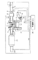
該第2の実施の形態の装置も、同じく自動車のエンジンシステムに適用され、空燃比フィードバック制御により燃料噴射量(時間)の補正を行うものである。ただし、同第2の実施の形態の装置にあっては図21に示すように、排気系4の構成が第1の実施の形態と相違しており、本実施の形態にあって、この排気系4は、触媒20、フロント酸素センサ11a及びリア酸素センサ11bを備えて構成されている。触媒20は前述のように、燃焼室3から排出される排気中に含まれる一酸化炭素(CO)、炭化水素(HC)、及び酸化窒素(NOx)を浄化するために設けられる。フロント酸素センサ11a及びリア酸素センサ11bはそれぞれこの触媒20の上流及び下流に設けられ、触媒通過及び後における排気中の酸素濃度を検出する。
【0184】
そして、本実施の形態にあっては、触媒20の下流に設けられたリア酸素センサ11bからのセンサ電圧VOrに基づいて前記第1の実施形態で説明した「空燃比フィードバック補正係数算出ルーチン」における空燃比フィードバック補正係数FAF算出に係るリッチ側見込みスキップ量RSRmk及びリーン側見込みスキップ量RSLmkをそれぞれ補正する。
【0185】
ここで、空燃比フィードバック補正係数FAFの算出に係る手順は、第1の実施形態で説明した「空燃比フィードバック補正係数算出ルーチン」(図7)によるものとほぼ同様のものである。ただし、同ルーチンのステップ202aにおけるリッチ側見込みスキップ量RSRmk及びリーン側見込み量RSLmkは、以下に説明する「サブフィードバック制御ルーチン」において算出されることとなる。
【0186】
図22及び図23には、「サブフィードバック制御ルーチン」に係る処理手順のフローチャートを示す。上述したように、このルーチンは、前記「空燃比フィードバック補正係数算出ルーチン」で用いられるリッチ側見込みスキップ量RSRmk及びリーン側見込みスキップ量RSLの算出及び更新を行うものであり、ECU30により所定周期毎に実行される。
【0187】
処理がこのルーチンに移行すると、ECU30は先ずステップ501において、現在の運転状態がサブフィードバック(サブF/B)制御を実行するための条件に適合しているか否かを判断する。当該条件は、基本的には第1の実施の形態において説明した空燃比フィードバック制御の適合条件(a1)〜(a5)と同様のものである。ただし、(a4)に相当する条件として、リア酸素センサ11bが活性化状態であることが必要とされる。そしてECU30は、当該サブフィードバック制御の実行条件を満たしている場合には処理をステップ502に移行し、同条件を満たしていなければ本ルーチンを一旦抜ける。
【0188】
続くステップ502、502a及び502bにおいては、リアセンサリッチ判定フラグXOXSRの設定又は設定解除を行う。リアセンサリッチ判定フラグXOXSRとは、リア酸素センサ11bからのセンサ電圧VOrに基づいて設定及び設定解除されるフラグであり、空燃比A/Fがリッチ側であれば「ON」に設定され、空燃比A/Fがリーン側であれば「OFF」に設定解除されるものである。
【0189】
すなわち、先ずステップ502においては、リア酸素センサ11bからのセンサ電圧VOrが基準電圧KOXRを上回っているか否かを判断する。そして、その判断が肯定であれば、ステップ502aに移行しリアセンサリッチ判定フラグXOXSRを「ON」に設定する。一方ステップ502における判断が否定であれば処理をステップ502bに移行し、リアセンサリッチ判定フラグXOXSRを「OFF」に設定解除する。そしてステップ502a及び502bのうち何れを経た場合も、処理をステップ503に移行する。
【0190】
ステップ503においては、リアセンサリッチ判定フラグXOXSRが「ON」に設定されているか否かを判断する。そして、その判断が肯定であれば処理をステップ504に移行し、その判断が否定であれば処理をステップ505に移行する。そして、ステップ504及び505のうち何れのステップにおいても、前回の処理においてリアセンサリッチ判定フラグXOXRが「ON」であると認識されたか否かを判断する。
【0191】
ステップ504における判断が肯定であれば、前回のルーチンから今回のルーチンに処理が移行する間にリア酸素センサ11bからのセンサ電圧に基づいて算出した空燃比A/Fはリッチの状態を継続しているとみなし、処理をステップ506aに移行する。一方、その判断が否定であれば、同空燃比A/Fがリーンからリッチに反転したとみなし、処理をステップ506bに移行する。
【0192】
ステップ506aにおいては、見込みスキップ補正量dlmkを「−a」%に設定する。他方、ステップ506bにおいては、見込みスキップ補正量dlmkを「−b」%に設定する。そして、ステップ506a及び506bのうち何れのステップで処理を行ったとしても、続く処理をステップ508(図23)に移行する。
【0193】
一方、ステップ505において、その判断が否定であれば、前回のルーチンから今回のルーチンに処理が移行する間にリア酸素センサ11bからのセンサ電圧に基づいて算出した空燃比A/Fはリーンの状態を継続しているとみなし、処理をステップ507aに移行する。一方、その判断が肯定であれば、同空燃比A/Fがリッチからリーンに反転したとみなし、処理をステップ507bに移行する。そして、ステップ507aにおいては見込みスキップ補正量dlmkを「−a」%に設定し処理をステップ508に移行する。他方、ステップ507bにおいては見込みスキップ補正量dlmkを「−b」%に設定し、この場合も処理をステップ508(図23)に移行する。
【0194】
ここで、前記ステップ506a,506b,507a及び507bにおいて、見込みスキップ補正量dlmkに代入される数値「a」及び数値「b」は共に正の定数であり、「a≪b」の関係にある。また、基本量となる空燃比フィードバック係数FAFに対し相対的には微小な数値(例えば、数値「a」は「0.01」%未満、数値「b」は「1」%未満)として設定される。
【0195】
ステップ508(図23)においては、上記ステップ506a、506b、507a及び507bのうち何れかのステップで設定された見込みスキップ補正量dlmkを
前回算出されたサブフィードバック見込みスキップ量RSmkに加算して、今回のサブフィードバック見込みスキップ量RSmkとする。
【0196】
続くステップ509においては、後続のステップ510,511,512でサブフィードバック見込みスキップ量RSmkに基づいて行う空燃比フィードバック補正係数FAFの各更新量RSR、RSL、RSLmk、RSLmkの設定に先だって、当該サブフィードバック見込みスキップ量RSmkの上下限ガードを行う。
【0197】
すなわち、サブフィードバック見込みスキップ量RSmkが下限値K6(<0)から上限値K7(>0)までの範囲内にあるか否かを判断するとともに、下限値K6を下回っている場合には同下限値K6に、上限値k7を上回っている場合には同上限値K7に設定しなおす。
【0198】
続くステップ510においては、今回上記ステップ508で算出したサブフィードバック見込みスキップ量RSmkが「0」%以上であるか否かを判断する。そして、その判断が肯定であれば処理をステップ511に移行し、その判断が否定であれば処理をステップ512に移行する。
【0199】
ステップ511においては、リッチ側スキップ量RSRを所定値K4(>0)、リーン側スキップ量RSLを所定値K5(>0)に設定するとともに、リッチ側見込みスキップ量RSRmk及びリーン側スキップ量RSLmkを何れも(所定値K0×サブフィードバック見込みスキップ量RSmk)として同値に設定する。
【0200】
一方、ステップ512においては、リッチ側見込みスキップ量RSRmk及びリーン側見込みスキップ量RSLmkをそれぞれ以下の演算式(5)及び(6)に従って算出する。
RSR=K4−K1×RSmk…(5)
RSL=K5+K2×RSmk…(6)
ただし、K1>0,K2>0
また、リッチ側見込みスキップ量RSRmk及びリーン側見込みスキップ量RSLmkをともに「0」として設定する。
【0201】
ECU30は、ステップ511及びステップ512のうち何れかを経た後、その後の処理を一旦終了する。
ECU30は、以上説明した「サブフィードバック制御ルーチン」により、空燃比フィードバック補正係数FAF算出に係る見込みスキップ量RSRmk及びRSLmk等の修正を行う。
【0202】
次に、上記「空燃比サブフィードバック制御ルーチン」で算出されたサブフィードバック見込みスキップ量RSmkがどのような態様で空燃比フィードバック補正係数FAFに反映されるのか、図を併せ参照して説明する。
【0203】
図24(a)及び図24(b)は、リア酸素センサ11bからのセンサ電圧VOrの変化態様及び同センサ電圧VOrに基づいて変更されていくサブフィードバック見込みスキップ量RSmkの変化態様をそれぞれ同一スケールの時間軸上に示したものである。
【0204】
一方図24(c)には、図24(b)上において、サブフィードバック見込みスキップ量RSmkが点α、点β、点γにあるとき、空燃比フィードバック補正係数FAFがどのような制御波形となるのかを例示する。
【0205】
先の「空燃比サブフィードバック制御ルーチン」において説明したように、ECU30は、触媒20下流に設けられたリア酸素センサ11bからのセンサ電圧VOrに基づきサブフィードバック見込みスキップ量RSmkを更新していく。例えば図24(a)及び(b)に示すように、センサ電圧VOrに基づく空燃比がリッチ側にある場合にはサブフィードバック見込みスキップ量RSmkを増大させ、リーン側にある場合には減少させる。そして、このような見込みスキップ量RSmkの変動を反映して、空燃比フィードバック補正係数FAFの制御波形も変化することとなる。
【0206】
すなわち、「サブフィードバック制御ルーチン」で説明したように、サブフィードバック見込みスキップ量RSmkが「0%」以上である場合には、ステップ511で示したように、リッチ側スキップ量RSR及びリーン側スキップ量RSLはそれぞれ所定値K4及びK5に固定される一方、リッチ側見込みスキップ量RSRmk及びリーン側見込みスキップ量RSLmkは、共にサブフィードバック見込みスキップ量RSmkの増減に比例して増減されることとなる。
【0207】
例えば、図24(b)上の点αと点βとを比較すると、図24(c)に示すように、点αにおける見込みスキップ量RSmkは点βにおける見込みスキップ量RSmkに比して大きい。この相違を反映して、点αにおいて設定される見込みスキップ量RSRmk、RSLmkは点βにおいて設定されるものより大きな値となる。
【0208】
一方、例えば図24(b)上における点γのように、サブフィードバック見込みスキップ量RSmkが「0%」未満である場合には、ステップ512で示したように、リッチ側見込みスキップ量RSRmk及びリーン側見込みスキップ量RSLmkをともに「0%」に設定するとともに、サブフィードバック見込みスキップ量RSmkに応じてリッチ側スキップ量RSR及びリーン側スキップ量RSLを操作する。この際、先の演算式(5)及び(6)からも明らかなように、サブフィードバック見込みスキップ量RSmk(<0)が小さいほどリッチ側スキップ量RSRは大きく、リーン側スキップ量RSLは小さく設定され、結果として、空燃比フィードバック補正係数FAFがリッチ側に偏在する傾向が強くなる(図24(c)を併せ参照)。
【0209】
すなわち、サブフィードバック見込みスキップ量RSmkが「0%」以上である場合には、空燃比フィードバック補正係数FAFの制御波形を見込みスキップ量RSRmk及びRSLmkの大きさで操作することにより、空燃比をリッチ側、或いはリーン側へ偏在させ、最適な排気空燃比を維持する。一方、サブフィードバック見込みスキップ量RSmkが「0%」を下回った場合には、空燃比フィードバック補正係数FAFの制御波形に係る見込みスキップ量RSRmk及びRSLmkは設けずに、同スキップ量RSR及びRSLの操作による制御波形の非対称化を行って排気空燃比をリッチに偏在させることとする。
【0210】
このように、本実施形態にあっては、空燃比フィードバック補正係数FAFの制御波形に係る制御量として見込みスキップ量RSmkを導入するとともに、リッチ側及びリーン側へのスキップ制御に係る見込みスキップ量を操作することによりFAFの制御波形の最適化を図ることができる。そして、排気空燃比の更なるリーン化が生じた場合には、見込みスキップ量の導入を中断するとともに、空燃比フィードバック補正係数FAFの非対称化により空燃比のリッチ側への偏在の効果を強化させる。こうして、制御波形の振幅や周波数は極力安定に保持した状態で空燃比補正係数FAFの制御中心をリッチ又はリーンに偏在させ、最適な排気空燃比を維持し、もって触媒の最適な浄化効率を得ることができるようになる。
【0211】
すなわち、フロント酸素センサ11aのばらつき等に起因する排気エミッションのばらつきも、上記空燃比サブフィードバック制御を通じて任意に、しかも的確に抑制することができるようになり、排気特性を一層向上できるようになる。
【0212】
以上説明したように、本実施形態によれば、第1の実施の形態による前記(1)〜(6)の効果に加えて、更に以下のような効果が奏せられるようになる。
(7)リア酸素センサからのセンサ電圧の適用による空燃比サブフィードバック制御を空燃比フィードバック制御に係る制御波形に乱れを生じさせることなく行えるようになり、排気特性の向上に係る効率を一層高めることができるようになる。
【0213】
なお、本実施形態にあって、上記「空燃比サブフィードバック制御ルーチン」の処理手順中、スキップ補正量dlmkは、リア酸素センサ11bのセンサ電圧VOrの挙動に対し、当該センサ電圧がリッチ側(VOr>KOXR)にある場合には「a」%分減量(「−a」%)、リーン側(VOr≦KOXR)にある場合にはa分増量(「+a」%)され、また、リーンからリッチへの反転時には「b」%分減量(「−b」%)、リッチからリーンへの反転時には「b」分増量(「+b」%)されることにより、見込みスキップ量RSmkの制御波形は図24(b)に示したように、増大側と減少側に対して互いにほぼ対称となる(センサ電圧VOrが対称形である場合)。これに対し、センサ電圧VOrがリッチ側にある場合、リーン側にある場合、リーンからリッチへの反転時、及びリッチからリーンへの反転時に応じてそれぞれ異なるスキップ補正量dlmkを設定すれば、図24(b)に示した見込みスキップ量RSmkの制御波形を非対称化する等、その波形特性を変更することができる。このような変更により、例えば、サブフィードバック見込みスキップ量が「0%」以上となる時間、すなわち空燃比フィードバック補正係数FAFの波形を見込みスキップ量RSRmk及びRSLmkにより操作する時間(図24(b)及び(c)参照)を柔軟に変更(伸縮)することができる。
【0214】
なお、本実施形態では、サブフィードバック見込み量RSmkの変動に応じてリッチ側見込みスキップ量RSRmkとリーン側見込みスキップ量RSLmkとの相対量を可変とする構成を用いた。
【0215】
これに対し、例えば図24のタイムチャート上におけるサブフィードバック見込みスキップ量RSmkの値に基づき複数の領域区画を行い、区画された領域ごとに空燃比フィードバック補正係数FAFの制御波形に係る見込みスキップ量RSRmk、RSLmk等を設定しておいてもよい。
【0216】
また、本実施形態においては、フロント酸素センサ11a及びリア酸素センサ11bは、所定のセンサ電圧KOXRを基準電圧として、空燃比がリッチ側に在るのかリーン側に在るのかを二者択一的に判断する、いわゆる濃淡電池型のものである。これに代えて、空燃比に応じてセンサ電圧が線形に変化する限界電流型の酸素センサを適用してもよい。この種の酸素センサを適用すれば、酸素センサからのセンサ電圧に基づく空燃比の制御中心(目標空燃比)を必ずしも一定にする(例えばFAF=1)必要がなく、本実施形態、あるいは先の第1の実施形態で行った制御と併せて空燃比の制御中心を柔軟に設定及び変更することができるようになり、また現在の空燃比の制御中心からのずれ量をより的確に把握しつつ空燃比制御を行うことができるようになる。
【0217】
その他、第1及び第2の実施形態においては、空燃比フィードバック補正係数FAFが燃料量(時間)の補正量として採用されるとしたが、空燃比を決定する他のパラメータ、例えばスロットルバルブ5がいわゆる電子式のスロットルバルブであるような場合にはアクセルの踏み込み量に対するスロットル開度を補正するような補正量として用いることもできる。
【0218】
さらに、第1及び第2の実施形態において、空燃比フィードバック制御に適用した見込み空燃比フィードバック補正係数FAFmkは、スキップ制御が行われた後、次回のスキップ制御まで一定の値を保持することとしている。これに対し、同見込み空燃比フィードバック補正係数FAFmkを、微小な変化率で積分制御するよう制御を構成してもよい。
【0219】
【発明の効果】
請求項1に記載した発明によれば、制御波形の振幅は抑制しつつ、スキップ制御による補正量の変動範囲のみを拡大することとなり、制御波形の周波数も増大することとなる。この結果、空燃比フィードバック制御の精度が増し、排気特性も一層向上するようになる。
【0221】
請求項2に記載した発明によれば、酸素センサからの検出信号がリッチ及びリーン間で反転する周期が短い場合、空燃比がリッチずれすることを好適に抑制し、空燃比フィードバック制御に係る制御中心の安定性を向上させることができるようになる。
【0222】
請求項3に記載した発明によれば、酸素センサからの検出信号がリッチ及びリーン間で反転する周期が短い場合、空燃比のリッチずれの抑制と空燃比フィードバック制御に係る制御中心の安定化が確実に行われるようになる。
【0223】
請求項4に記載した発明によれば、インジェクタの流動特性や吸気系内での空気分配、パージ分配の不具合に起因して空燃比補正量の制御波形にチャタリングが生じたときに、このチャタリング発生時に空燃比補正量の制御波形が非対称形である場合であれ、制御波形の中心がずれてしまうことを好適に抑制することができるようになる。
【0224】
請求項5に記載した発明によれば、空燃比フィードバック制御の制御波形に係る振幅の増大や周波数の低下を伴うことなく、空燃比補正量の制御中心をリッチ側へ偏在させることができ、空燃比センサの応答遅れに起因するリーンずれを好適に修正することができるようになる。
【0225】
請求項6に記載した発明によれば、空燃比フィードバック制御に係る制御波形について、振幅の縮減及び周波数の増大という面で、運転状態に応じた最適な波形を形成することができるようになり、ひいては一層緻密な空燃比制御を行うことができるようになる。
【0226】
請求項7に記載した発明によれば、触媒上流に設けられた空燃比センサからの検出信号のばらつきを好適に修正して、一層緻密性の高い空燃比フィードバック制御を実行することができるようになる。
【0227】
請求項8に記載した発明によれば、空燃比フィードバック制御の制御条件からはずれることなく、しかも当該制御に係る制御波形の振幅を増大することもなく空燃比を低下させ、好適に触媒の床温低下を促すことができるようになる。
【0228】
請求項9又は10に記載した発明によれば、請求項8に記載した発明の実施に際して制御波形の周波数低下を好適に抑制し、空燃比フィードバック制御の緻密性を好適に保持することができるようになる。
【図面の簡単な説明】
【図1】本発明に係る空燃比制御装置の第1の実施形態を示す概略構成図。
【図2】同実施形態に採用されるECUの電気的構成を示すブロック図。
【図3】酸素センサからのセンサ電圧及び空燃比フィードバック補正係数等の変化態様を示すタイムチャート。
【図4】空燃比制御手順を総括的に示すフローチャート。
【図5】条件設定手順を示すフローチャート。
【図6】条件設定手順を示すフローチャート。
【図7】空燃比フィードバック補正係数算出手順を示すフローチャート。
【図8】空燃比フィードバック補正係数算出手順を示すフローチャート。
【図9】空燃比フィードバック補正係数の制御波形。
【図10】実際の空燃比及び酸素センサからのセンサ電圧を示すタイムチャート。
【図11】空燃比フィードバック制御に係る制御波形。
【図12】応答遅れ及びスキップ量学習手順を示すフローチャート。
【図13】応答遅れ及びスキップ量学習手順を示すフローチャート。
【図14】空燃比フィードバック補正係数、リッチ側応答遅れカウンタ及びリーン側応答遅れカウンタの変化態様を示すタイムチャート。
【図15】応答遅れ及びスキップ量学習により変更される空燃比フィードバック補正係数の制御波形。
【図16】ホールド制御での空燃比フィードバック補正係数及び酸素センサからのセンサ電圧の変化態様を示すタイムチャート。
【図17】ホールド制御手順を示すフローチャート。
【図18】ホールド制御手順を示すフローチャート。
【図19】チャタリング発生時の空燃比フィードバック補正係数の変化態様を示すタイムチャート。
【図20】他の実施態様に係る空燃比制御手順の一部を示すフローチャート。
【図21】本発明に係る空燃比制御装置の第2の実施形態を示す概略構成図。
【図22】サブフィードバック制御手順を示すフローチャート。
【図23】サブフィードバック制御手順を示すフローチャート。
【図24】リア酸素センサからのセンサ電圧、見込みスキップ量、及び空燃比フィードバック補正係数の制御波形。
【符号の説明】
1…エンジン、2…吸気系、3…燃焼室、4…排気系、5…スロットルバルブ、6…サージタンク、7…吸気量センサ、8…スロットルポジションセンサ(開度センサ)、9…吸気温センサ、10…燃料噴射弁、11…酸素センサ、11a…フロント酸素センサ、11b…リア酸素センサ、12…イグナイタ、13…ディストリビュータ、14…点火プラグ、15…回転数センサ、 16…気筒判別センサ、17…水温センサ、20…触媒(三元触媒)、30…ECU(電子制御装置、31…マイクロコンピュータ、31a…CPU、31b…ROM、31c…RAM、31d…バックアップRAM、34…A/D変換回路、35…駆動回路。[0001]
TECHNICAL FIELD OF THE INVENTION
The present invention relates to an air-fuel ratio control device for an internal combustion engine that performs feedback control to optimize the air-fuel ratio of a combustible air-fuel mixture supplied to the internal combustion engine.
[0002]
[Prior art]
2. Description of the Related Art As one of devices for controlling the operation state of a vehicle-mounted internal combustion engine (engine), there is an air-fuel ratio control device for controlling an air-fuel ratio of an air-fuel mixture supplied to a combustion chamber of the engine. Generally, the air-fuel ratio required for an engine changes according to the engine speed, load state, warm-up state, and the like. Therefore, in this air-fuel ratio control device, by controlling the fuel injection device (fuel injection valve) through the electronic control device, the amount of fuel supplied to the combustion chamber is corrected, and the air-fuel ratio of the air-fuel mixture is adjusted. Through this adjustment, output stability and drivability of the engine are improved in accordance with various operating conditions of the engine, and exhaust characteristics are optimized.
[0003]
Here, the feedback control of the air-fuel ratio by the air-fuel ratio control device is specifically executed based on the following mechanism.
That is, in the air-fuel ratio feedback control, first, a basic fuel injection amount (time) is calculated based on operating state parameters such as an engine speed and an intake air amount, and an air-fuel ratio feedback correction coefficient, The target fuel injection amount (time) is determined in consideration of the air-fuel ratio learning value and a correction coefficient based on other various operating states. The air-fuel ratio feedback correction coefficient corresponds to the amount of deviation of the air-fuel ratio of the previous fuel injection from the stoichiometric air-fuel ratio (or the target air-fuel ratio), and the air-fuel ratio of the current fuel injection is calculated by the stoichiometric air-fuel ratio. This is a correction coefficient for approaching.
[0004]
The fuel injection amount is increased if the air-fuel ratio calculated based on the detection signal from the air-fuel ratio sensor (oxygen sensor) provided in the exhaust system of the engine is higher than the stoichiometric air-fuel ratio, and is decreased if the air-fuel ratio is lower than the stoichiometric air-fuel ratio. , The fuel injection amount is periodically corrected.
[0005]
[Problems to be solved by the invention]
By the way, in the device that controls the air-fuel ratio based on such a mechanism, when increasing or decreasing the correction amount by the feedback control, a response delay caused by a gas transport time from the combustion chamber to the oxygen sensor or a response time of the oxygen sensor is caused. Occurs. Therefore, normally, when reversing the correction mode of the fuel injection amount from increase to decrease or from decrease to increase, skip control for skipping a predetermined amount in anticipation of this response delay, and integration for gradually changing the skipped correction amount By performing the control, the response of the control system is enhanced. However, if the rate of change related to the correction amount gradual change during integration control is too large, the amplitude of the control waveform will be large, and if too small, the interval between the skip to the rich side and the skip to the lean side will be delayed. The frequency of the waveform is reduced. In either case, an increase in torque fluctuation and a decrease in drivability are promoted, and the exhaust characteristics are deteriorated. For this reason, it is indispensable for precise air-fuel ratio feedback control to always set the skip amount related to the skip control and the rate of change related to the correction amount gradual change at the time of integral control to optimal values.
[0006]
Conventionally, as disclosed in Japanese Patent Application Laid-Open No. 58-53661, the skip correction amount and the integral correction amount are increased to increase the air-fuel ratio correction amount so that the control air-fuel ratio becomes the optimum air-fuel ratio in terms of exhaust purification. Although the asymmetry is made between the side and the decrease side, in this case, the increase in the amplitude of the control waveform and the decrease in the frequency due to the response delay are unavoidable.
[0007]
The present invention has been made in view of such circumstances, and aims at optimizing a control waveform relating to air-fuel ratio feedback control, thereby further suppressing torque fluctuation and further improving exhaust characteristics. An object of the present invention is to provide an air-fuel ratio control device for an internal combustion engine which can achieve the following.
[0008]
[Means for Solving the Problems]
To achieve the above object, the invention according to
[0009]
According to this configuration, while suppressing the amplitude of the control waveform, only the variation range of the correction amount due to the skip control is expanded, and the frequency of the control waveform also increases. As a result, the accuracy of the air-fuel ratio feedback control is increased, and the exhaust characteristics are further improved.
[0011]
According to a second aspect of the present invention, in the air-fuel ratio control apparatus for an internal combustion engine according to the first aspect, the correction means includes: Based on the skip amount before increasing When the detected exhaust air-fuel ratio is reversed from lean to rich or from rich to lean during a period until the air-fuel ratio correction amount calculated by the integration control becomes the updated air-fuel ratio correction amount with the increased skip amount. , Based on the skip amount before increasing The gist is that the predetermined amount of skip control is performed using the air-fuel ratio correction amount calculated by the integration control as a reference amount.
[0012]
According to the configuration, when the cycle of inversion of the detection signal from the oxygen sensor from rich to lean is short, it is preferable to suppress the air-fuel ratio from being richly deviated, and conversely, when the cycle of inversion from lean to rich is short. Therefore, it is possible to improve the stability of the control center related to the air-fuel ratio feedback control by suitably suppressing the lean shift of the air-fuel ratio.
[0013]
According to a third aspect of the present invention, in the air-fuel ratio control apparatus for an internal combustion engine according to the second aspect, the correction means includes: Based on the skip amount before increasing When the detected exhaust air-fuel ratio is inverted from rich to lean during a period until the air-fuel ratio correction amount calculated by the integration control becomes the updated air-fuel ratio correction amount with the increased skip amount, the detected air-fuel ratio increases. The gist is that the skip control is performed using the air-fuel ratio correction amount updated with the skip amount as a reference amount.
[0014]
According to this configuration, when the cycle of inversion of the detection signal from the oxygen sensor between rich and lean is short, the rich deviation of the air-fuel ratio is suppressed and the control center related to the air-fuel ratio feedback control is reliably stabilized. become.
[0015]
[0016]
According to this configuration, when chattering occurs in the control waveform of the air-fuel ratio correction amount due to a flow characteristic of the injector, air distribution in the intake system, or a failure in the purge distribution, the air-fuel ratio correction amount is reduced when the chattering occurs. Even if the control waveform is asymmetric, the deviation of the center of the control waveform can be suitably suppressed.
[0017]
[0018]
The response time of the oxygen sensor, which is one of the factors that cause the response delay of the air-fuel ratio feedback control system, is longer when the actual air-fuel ratio reverses from rich to lean than when it reverses from lean to rich. It is known. Unless the deviation observed in the response time of the oxygen sensor, that is, the deviation relating to the inversion from rich to lean and the inversion from lean to rich, the control center of the air-fuel ratio tends to lean.
[0019]
Therefore, the
[0020]
[0021]
According to the configuration, the control waveform related to the air-fuel ratio feedback control can be formed with an optimal waveform in accordance with the operation state in terms of the reduction of the amplitude and the increase of the frequency. Fuel ratio control can be performed.
[0022]
[0023]
According to this configuration, it is possible to appropriately correct the variation in the detection signal from the air-fuel ratio sensor provided upstream of the catalyst, and to execute the air-fuel ratio feedback control with higher precision.
[0024]
[0025]
An exhaust gas purifying catalyst for purifying carbon monoxide, hydrocarbons and nitrides in exhaust gas is mounted in a catalytic converter provided in the exhaust system. It is well known that the exhaust gas purification catalyst has a high oxygen concentration (lean) and accelerates its deterioration in a state where the temperature of the catalyst is high, for example, because the noble metal is likely to aggregate. As described above, when the temperature of the exhaust gas purifying catalyst excessively rises, it is usual to take measures such as stopping the air-fuel ratio feedback control, increasing the fuel injection amount, and decreasing the oxygen concentration. However, if the fuel injection amount is increased in such a manner, the air-fuel ratio cannot be precisely controlled while the air-fuel ratio feedback control is stopped. For this reason, there has been a problem that the exhaust characteristics are not stabilized until the air-fuel ratio feedback control is restarted. In this regard, the
[0026]
Claim 9 The invention described in the
[0027]
[0028]
Claims above 9 Or 1 0 According to the configuration of the invention described in the above, the
[0029]
BEST MODE FOR CARRYING OUT THE INVENTION
(1st Embodiment)
Hereinafter, a first embodiment of an air-fuel ratio control apparatus for an internal combustion engine according to the present invention will be described with reference to the drawings.
[0030]
FIG. 1 is a schematic configuration diagram illustrating an engine system of an automobile including an air-fuel ratio control device according to the present embodiment.
In this system, the
[0031]
The
[0032]
Among these sensors, the intake
[0033]
The
[0034]
On the other hand, the
[0035]
In addition, the
[0036]
Further, the
[0037]
The
[0038]
In such an engine system, the output of each sensor described above is input to an electronic control unit (hereinafter, referred to as an ECU) 30 that plays a role of a control system of the
[0039]
FIG. 2 shows an outline of a hardware configuration of the
As shown in FIG. 2, the
[0040]
The input ports of the
[0041]
Next, an outline of the air-fuel ratio control among the various controls executed by the
The
[0042]
Here, characteristics of the air-fuel ratio feedback correction coefficient FAF employed in the present embodiment will be described based on a detection signal from the
In the present embodiment, when calculating the air-fuel ratio feedback correction coefficient FAF used for correcting the basic fuel injection amount (time) TAUbs, a so-called well-known air-fuel ratio feedback correction coefficient (referred to as a basic air-fuel ratio feedback correction coefficient in this embodiment) FAFbs. , An estimated air-fuel ratio feedback correction coefficient FAFmk.
[0043]
More specifically, while calculating both correction coefficients FAFbs and FAFmk separately in each routine processing by the
[0044]
For example, FIG. 3 shows a detection signal (sensor voltage) VO from the
[0045]
First, FIG. 3A shows a signal waveform of a sensor voltage VO which is a detection signal from the
[0046]
Next, FIG. 3B shows a waveform (broken line) of the basic air-fuel ratio feedback correction coefficient FAFbs. The basic air-fuel ratio feedback correction coefficient FAFbs is used to sequentially feed back the judgment (rich side or lean side) of the
[0047]
Here, for example, when the judgment of the
[0048]
FIG. 3C shows a waveform (dot-dash line) of the estimated air-fuel ratio feedback correction coefficient FAFmk. It is assumed that the estimated air-fuel ratio feedback correction coefficient FAFmk is updated each time the basic air-fuel ratio feedback correction coefficient FAFbs is skipped using the correction coefficient FAFbs as a reference value. In the calculation, as shown in FIG. 3C, the expected skip amount RSRmk or the expected skip amount RSLmk is added to the basic air-fuel ratio feedback correction coefficient FAF at the time of skipping. Then, the updated value (FAFmk) is held until the next skip.
[0049]
FIG. 3D shows the waveform of the basic air-fuel ratio feedback correction coefficient FAFbs (broken line) and the waveform of the expected air-fuel ratio feedback correction coefficient FAFmk (dashed line) on the same scale of time axis (horizontal axis) and control amount. This is superimposed on (vertical axis).
[0050]
As shown in FIG. 3D, both correction coefficients FAFbs and FAFmk perform rich skip and lean skip at the same timing. For example, at the time of the rich skip, the estimated air-fuel ratio feedback correction coefficient FAFmk exceeds the basic air-fuel ratio feedback correction coefficient FAFbs by the estimated skip amount RSRmk. In the subsequent integration control period, the basic air-fuel ratio feedback correction coefficient FAFbs gradually increases, but the expected air-fuel ratio feedback correction coefficient FAFmk holds a constant value. Therefore, after the predetermined time has elapsed, after the point A, the basic air-fuel ratio feedback correction coefficient FAFbs exceeds the expected air-fuel ratio feedback correction coefficient FAFmk.
[0051]
On the other hand, during the lean skip, the estimated air-fuel ratio feedback correction coefficient FAFmk is smaller than the basic air-fuel ratio feedback correction coefficient FAFbs by the estimated skip amount RSLmk. In the subsequent integration control period, the basic air-fuel ratio feedback correction coefficient FAFbs gradually decreases, but the expected air-fuel ratio feedback correction coefficient FAFmk maintains a constant value. For this reason, after the elapse of the predetermined time, after the point B, the basic air-fuel ratio feedback correction coefficient FAFbs becomes smaller than the expected air-fuel ratio feedback correction coefficient FAFmk.
[0052]
Here, the
[0053]
When the target fuel injection amount (time) TAUf is calculated by correcting the basic fuel injection amount (time) TAUbs, the air-fuel ratio feedback correction coefficient FAF is used, for example, in the following calculation.
TAUf = TAUbs × FAF × k1 × k2 ×... Kn (1)
However, k1 to kn are correction coefficients in consideration of various operating states such as warm-up, acceleration / deceleration, and output increase, and are separately calculated in a processing routine (not shown).
[0054]
Hereinafter, the air-fuel ratio control according to the present embodiment performed using the above-described feedback correction coefficient FAF will be described in detail.
First, an outline of a series of air-fuel ratio control according to the present embodiment will be described.
[0055]
The flowchart shown in FIG. 4 is a main routine for executing the air-fuel ratio control according to the present embodiment, and particularly shows a general control procedure related to the calculation of the feedback correction coefficient FAF. This routine is executed by the
[0056]
As shown in the figure, in the present embodiment, the control related to the calculation of the air-fuel ratio feedback correction coefficient is roughly divided into a condition setting routine in step 001, a catalyst bed temperature determination step in
[0057]
When the process proceeds to this routine, first, in the condition setting routine of step 001, the
[0058]
Next, in
[0059]
In the series of air-fuel ratio feedback control according to steps 003 to 004, basically, the air-fuel ratio feedback correction coefficient FAF using the waveform described in FIG. 3 is calculated (step 003), and then the air-fuel ratio feedback control is performed. The learning control of the response delay amount and the skip amount according to (1) is performed (step 004), and a series of processes related to the main routine is temporarily terminated.
[0060]
Next, the specific processing contents of the respective steps 001 to 005 will be sequentially described.
FIG. 5 shows that among the control routines constituting the main routine (see FIG. 4), it is determined whether or not the current operating state is in a state suitable for the air-fuel ratio feedback control. The processing content of a “condition setting routine” (step 001 in FIG. 4) for storing and updating information necessary for air-fuel ratio control based on the sensor voltage is shown.
[0061]
When the process proceeds to this routine, the
(A1) Not at the time of starting.
(A2) The fuel is not being cut.
(A3) The cooling water temperature THW is equal to or higher than a predetermined temperature.
(A4) The
(A5) The engine is not in a high load or high revolution state.
(A6) The catalyst bed temperature is lower than a predetermined temperature td.
When all of the above conditions (a1) to (a6) are satisfied, it is determined that the current operating condition is suitable for the condition for performing the air-fuel ratio feedback control, and the process proceeds to step 102a. I do. On the other hand, if any one of the above conditions is not satisfied, it is determined that the current operating state does not meet the condition for performing the air-fuel ratio feedback control, and the process proceeds to step 102b.
[0062]
In
[0063]
In
[0064]
In a series of
[0065]
That is, first, in
[0066]
In the
[0067]
In
[0068]
In
[0069]
On the other hand, if the process proceeds to step 110 after
[0070]
That is, first, in
[0071]
In the
[0072]
In
[0073]
In
In
[0074]
In
[0075]
Then, after going through either step 121 or step 122, the
The skip timing flag XRQSKP is cleared ("OFF") in a "feedback correction coefficient calculation routine" described later.
[0076]
Next, of the series of subroutines relating to the air-fuel ratio control described in FIG. 4, the details of the processing content of the air-fuel ratio feedback correction coefficient calculation routine of step 003 executed to calculate the air-fuel ratio feedback correction coefficient FAF will be described. I do.
[0077]
FIGS. 7 and 8 show flowcharts of a processing procedure related to the air-fuel ratio feedback correction coefficient calculation routine.
When the process proceeds to this routine, the
(B1) FAFbs = 1
(B2) FAFmk = 1
(B3) FAF = 1
Then, the
[0078]
On the other hand, in
[0079]
In the
[0080]
In
From
[0081]
In
[0082]
In the
[0083]
In the
[0084]
On the other hand, if the determination in the
[0085]
In the
[0086]
In the
[0087]
After step 205, processing related to integral control for gradually changing the air-fuel ratio feedback correction coefficient FAF is performed. That is, first, in step 205, the setting state of the rich determination flag XOXR is determined. If the setting state is "ON", the process proceeds to step 210, and if the setting state is "OFF", the process proceeds to step 220 (FIG. 8).
[0088]
In
[0089]
In the
[0090]
On the other hand, when the determination in the previous step 205 is negative and the process proceeds to step 2220, in the
[0091]
In the
[0092]
After passing through
[0093]
By the way, in a series of processes for skip control related to the
[0094]
The expected air-fuel ratio feedback correction coefficient FAFmk calculated in the
[0095]
Then, after the determination in any of the
[0096]
For example, FIGS. 9A and 9B show, on a time chart, an example of how the air-fuel ratio feedback correction coefficient FAF according to the skip control in the air-fuel ratio feedback control according to the present embodiment changes.
[0097]
First, as shown in FIG. 9A, at the time of lean skip, the air-fuel ratio feedback correction coefficient FAF is a predetermined amount (RSL + RSLmk) with respect to the point L1 to the point L2, that is, the basic air-fuel ratio feedback correction coefficient FAFbs immediately before skipping. Move to the subtracted value.
[0098]
As shown in FIG. 9B, during the rich skip, the air-fuel ratio feedback correction coefficient FAF is a predetermined amount (RSR + RSRmk) with respect to the point R1 to the point R2, that is, the basic air-fuel ratio feedback correction coefficient FAFbs immediately before the skip. Move to the added value.
[0099]
The manner of shifting the air-fuel ratio feedback correction coefficient FAF during the skip control is applied for the following reason.
In performing the air-fuel ratio feedback control, the fluctuation period of the sensor voltage VO by the oxygen sensor, that is, from the time when the sensor voltage VO is inverted from lean to rich to the next time from lean to rich, or from the time when the sensor voltage VO is inverted from rich to lean next time. The length of the transition from rich to lean varies depending on the flow velocity of the exhaust gas (intake amount Ga), the distance from the combustion chamber to the oxygen sensor, the structure of the exhaust passage, the responsiveness of the oxygen sensor itself, and the like.
[0100]
On the other hand, between the actual air-fuel ratio A / F and the sensor voltage VO recognized by the ECU, the response delay of the oxygen sensor, including the delay processing time described in the condition setting routine (FIGS. 5 and 6). It is widely known that there is a time delay (phase difference of the fluctuation period) caused by the following.
[0101]
For example, FIGS. 10A and 10B show the actual air-fuel ratio A / F and the sensor voltage VO on the same time axis, respectively.
As shown in FIGS. 10A and 10B, the time delay of the sensor voltage VO with respect to the behavior of the air-fuel ratio A / F is richer than that related to the inversion from lean to rich (rich side time delay ΔTLR). It is known that the one related to inversion to lean (lean time delay ΔTRL) is longer. Further, the time delays ΔTRL and ΔTLR tend to be shorter as the fluctuation cycle of the sensor voltage VO is shorter, and longer as the fluctuation cycle is longer.
[0102]
Therefore, in a control system having a long fluctuation cycle of the sensor voltage VO, the difference (ΔTLR−ΔTRL) between the lean time delay and the rich time delay increases. In other words, the sensor voltage VO quickly reverses to the rich side with respect to the actual fluctuation of the air-fuel ratio A / F, while the reverse to the lean side has a tendency to slow down. Tendency to increase. Conversely, in a control system in which the fluctuation period of the sensor voltage VO is short, the tendency that the air-fuel ratio A / F is relatively unevenly distributed to the rich side increases.
[0103]
In this regard, if the skip control is performed in the manner shown in FIGS. 9A and 9B, the amplitude of the air-fuel ratio feedback correction coefficient FAF is reduced, the control frequency is increased, and naturally, The expansion of the difference (ΔTLR−ΔTRL) between the lean time delay and the rich time delay can also be suppressed, and the air-fuel ratio A / F can be precisely converged to the target value.
[0104]
That is, in the present embodiment, by using the above-described processing procedure, the reference point of the subtraction of the lean side skip amount (RSL + RSLmk) or the addition of the rich side skip amount (RSR + RSRmk) is changed. By reducing the amplitude and increasing the frequency of the control waveform of the fuel ratio feedback correction coefficient FAF, a rich deviation or a lean deviation of the air-fuel ratio due to the fluctuation cycle of the sensor voltage VO is suitably suppressed.
[0105]
In addition, in order to keep the tolerance between the actual target air-fuel ratio and the FAF after skipping constant, the air-fuel ratio feedback correction related to the skip control is performed in another mode (hereinafter referred to as a second mode) as described below. A coefficient calculation mode may be configured.
[0106]
That is, FIGS. 9 (c) and 9 (d) show, on the time chart, another aspect of the skip control of the air-fuel ratio feedback control according to the present invention as a variation of the air-fuel ratio feedback correction coefficient FAF.
[0107]
First, as shown in FIG. 9 (c), the air-fuel ratio feedback correction coefficient FAF at the time of the lean skip is a predetermined amount (RSL + RSLmk) using the basic air-fuel ratio feedback correction coefficient FAFbs immediately before the skip from the point L1 to the point L2. The transition to the value obtained by subtracting is the same as in the mode shown in FIG.
[0108]
However, in the second mode, during the rich skip, as shown in FIG. 9B, when the air-fuel ratio feedback correction coefficient FAF shifts from the point R1 to the point R2, the air-fuel ratio feedback correction coefficient FAF (FAFmk ) Is used as a reference value, and a transition is made to a value obtained by adding a predetermined amount (RSR + RSRmk). However, as shown in FIG. 9D, when performing skip control after the basic air-fuel ratio feedback correction coefficient FAFbs crosses the expected air-fuel ratio feedback correction coefficient FAFmk during the rich skip, the basic air-fuel ratio feedback correction is performed. With the coefficient FAFbs as a reference value, the skipped air-fuel ratio feedback correction coefficient FAF is shifted to a value obtained by adding a predetermined amount (RSR + RSRmk). That is, in the second mode, at the time of the rich skip, the control is performed such that the skip control is performed using the air-fuel ratio feedback correction coefficient FAF applied immediately before the skip as a reference value.
[0109]
According to the second aspect, by applying the aspect of FIG. 9C, there is a tendency that the richer the air-fuel ratio A / F is, the more the oxygen sensor having a shorter inversion cycle of the sensor voltage VO is used. 9 (d) and (d '), the air-fuel ratio A / F shifts richer as the oxygen sensor having a shorter inversion cycle of the sensor voltage VO is used. The tendency of the air-fuel ratio to be easily controlled is sufficiently suppressed, and even if the reversal cycle of the sensor voltage from the oxygen sensor varies, the tolerance variation between the target air-fuel ratio and the skipped air-fuel ratio feedback correction coefficient FAF is appropriately suppressed. .
[0110]
Now, in the "feedback correction coefficient calculation routine" shown in FIGS. 7 and 8, when the processing is shifted to step 250 (FIG. 8) through step 221 (FIG. 8) or step 242 (FIG. 8), In, it is determined whether the basic air-fuel ratio feedback correction coefficient FAFbs calculated this time is lower than the expected air-fuel ratio feedback correction coefficient FAFmk. If the determination in
[0111]
On the other hand, when the process proceeds to step 260 (FIG. 8) after step 211 (FIG. 7) or step 232 (FIG. 7), the basic air-fuel ratio feedback correction coefficient FAFbs calculated this time is It is determined whether or not it is equal to or more than the expected feedback correction coefficient FAFmk. If the determination in
[0112]
Finally, when the process proceeds to step 251, the
[0113]
The
[0114]
That is, both the basic air-fuel ratio feedback correction coefficient FAFbs and the expected feedback correction coefficient FAFmk calculated by the
[0115]
FIG. 11 shows, by way of example, a control waveform of the air-fuel ratio feedback correction coefficient FAF related to the air-fuel ratio feedback control that takes one period from the rich skip to the lean skip. FIG. 11A shows a control waveform according to the conventional air-fuel ratio feedback control, FIG. 11B shows a rectangular control waveform, and FIG. 11C shows a control waveform employed in the present embodiment. 3 shows a control waveform. In addition, the areas (shaded portions) obtained with the control waveforms shown in FIGS. 11A to 11C are all the same, which means that the total correction amount (increase) of the fuel injection amount TAU is substantially equal. Means that.
[0116]
As is apparent from comparison of FIGS. 11A to 11C, the amplitude of the air-fuel ratio feedback correction coefficient FAF employing the conventional control waveform (FIG. 11A) is the largest of the three, and the control time Is also the longest.
[0117]
Therefore, to minimize the control time while minimizing the amplitude of the air-fuel ratio feedback correction coefficient FAF, it is considered most preferable to employ a rectangular control waveform (FIG. 11B).
[0118]
However, if a rectangular control waveform is adopted, there is a problem that the frequency tends to fluctuate unless an appropriate skip amount is set in advance. This is because the control time easily expands and contracts because the air-fuel ratio feedback correction coefficient FAF is not gradually changed during the integration control. Such susceptibility to control time fluctuation is particularly remarkable in a transient operation state in which the amount of change in the intake air amount Ga or the like of the
[0119]
In this regard, according to the control waveform (FIG. 11C) of the air-fuel ratio feedback correction coefficient FAF in the present embodiment, the frequency can be increased while the amplitude can be suppressed, and thus the air-fuel ratio feedback with high density and high response can be achieved. Control can be performed. Thereby, suppression of torque fluctuation and drivability are improved, and exhaust characteristics are also optimized.
[0120]
Further, as is clear from the description of the “air-fuel ratio feedback correction coefficient calculation routine”, the control waveforms of the air-fuel ratio feedback correction coefficient FAF include the skip amounts RSR and RSL, the expected skip amounts RSRmk and RSL, and the integral amounts KiR and It will be determined by the components consisting of KiL. That is, by changing each of these control amounts, the control waveform is asymmetrical, or the control center (basically “1”) of the air-fuel ratio feedback correction coefficient FAF is corrected to the rich side or the lean side. Also becomes easier.
[0121]
Next, among the series of routines related to the air-fuel ratio feedback control described with reference to FIG. 4, details of the processing contents of the response delay and skip amount learning routine of
[0122]
As described with reference to FIGS. 3A to 3E, in the air-fuel ratio feedback control according to the present embodiment, during the integral control period after the air-fuel ratio feedback correction coefficient FAF is lean skipped or rich skipped, It is kept at a fixed amount for a predetermined time, and then changes gradually thereafter. The control waveform of the air-fuel ratio feedback correction coefficient FAF formed as a result is as shown in FIG.
[0123]
Therefore, the response delay and skip amount learning routine is for further optimizing the waveform of the air-fuel ratio feedback correction coefficient FAF sequentially calculated in the “air-fuel ratio feedback correction coefficient calculation routine”. In addition to simultaneously increasing the frequency related to the waveform and suppressing the amplitude, the information related to the waveform, that is, the control response delays dlRSR, dlRSL, and the skip amount RSR are provided for each of a plurality of operating regions defined based on the intake air amount Ga. , RSL, and the expected skip amounts RSRmk, RSLmk.
[0124]
FIGS. 12 and 13 show flowcharts of the processing procedure relating to the response delay and skip amount learning routine.
When the process proceeds to this routine, the
[0125]
In
[0126]
In
[0127]
In
[0128]
Incidentally, as shown in FIG. 14, the rich side response delay counter CFAFR is reset every time the air-fuel ratio feedback correction coefficient FAF (FIG. 14 (a)) is rich skipped while counting up at predetermined intervals (FIG. 14 (b)). On the other hand, the lean-side response delay counter CFAFL is reset every time the air-fuel ratio feedback correction coefficient FAF (FIG. 14A) lean-skips while counting up at predetermined intervals (FIG. 14C).
[0129]
In the subsequent step 305a, the expected air-fuel ratio feedback correction coefficient FAFmk and the basic air-fuel ratio feedback correction coefficient FAFbs calculated this time in the preceding air-fuel ratio feedback control routine are used, and the following equation (2) is used. , A deviation between the two (hereinafter referred to as “probable amount−basic amount deviation”) dlmkbs is calculated.
dlmkbs = FAFmk−FAFbs (2)
Here, the expected amount-basic amount deviation dlmkbs is a difference between the estimated air-fuel ratio feedback correction coefficient FAFmk and the basic air-fuel ratio feedback correction coefficient FAFbs. In this case, particularly, in this case, immediately before both correction coefficients are inverted from lean to rich. Corresponds to the deviation of
[0130]
In
[0131]
In steps 307a1 and 307a2, the latest history of the skip amount RSR when the air-fuel ratio feedback correction coefficient FAF is inverted from lean to rich is updated as a learning value. When calculating the skip amount RSR, first, a change amount dlRSR of the skip amount RSR is calculated based on the estimated amount-basic amount deviation dlmkbs calculated in step 305a. Then, the change amount dlRSR is further added to the old learning value RSRi-1 of the skip amount RSR, and this value is set as the latest learning value. The learning value (skip amount) RSR is stored in the backup RAM 31d as a learning value for a region corresponding to the current operation region (Ga) among a plurality of operation regions partitioned based on the intake air amount Ga. It becomes. Then, after the processing in step 307a1, the processing shifts to step 308a, and after the processing in step 307a2, the processing jumps to step 309a. Note that the change amount dlRSR obtained in the processing in step 307a1 based on the expected amount-basic amount deviation dlmkbs is an update amount for increasing the rich-side skip amount RSR, whereas the change amount dlRSR obtained in the processing in step 307a2 is The amount dlRSR is an update amount for decreasing the rich-side skip amount RSR. Therefore, the change amount dlRSR obtained in step 307a1 has a positive value, and the change amount dlRSR obtained in step 307a2 has a negative value.
[0132]
In step 308a, as shown in FIG. 14A, the current value of the rich-side response delay counter CFAFR is compared with the rich-side response delay time dtRi-1 stored in the backup RAM 31d as the old learning value. dtRi) is stored and updated in the backup RAM 31d as the latest learning value dtR. As shown in step 308a in the flowchart of FIG. 12, the latest learning value is calculated as the average value of the old learning value dtRi-1 and the rich-side response delay counter CFAFR (dtRi). In order to suppress such fluctuations, the contribution ratio of the rich-side response delay counter CFAFR to the latest learning value dtR is set to a small value (1/64 smoothing (gradual change)).
[0133]
In
RSRmk = dtR × Kir ... (3)
Then, the expected skip amount RSRmk is also stored in the backup RAM 31d as a learning value related to the current operation area in light of the intake air amount Ga. After the processing in
[0134]
In the series of processing in
[0135]
On the other hand, when the determination in
[0136]
The
[0137]
FIG. 15 schematically shows how the control waveform of the air-fuel ratio feedback correction coefficient FAF is changed by the response delay and skip amount learning routine, taking a period from rich skip to lean skip as an example. It is shown.
[0138]
For example, when the basic air-fuel ratio feedback correction coefficient FAFbs immediately before the lean skip exceeds the expected air-fuel ratio feedback correction coefficient FAFmk as in the control waveform shown in FIG. The "learning routine" (FIG. 12) performs processing in the following procedure to approximate the control waveform to a rectangle based on the determination in
(A1) The skip amount RSR at the time of the next rich skip is increased and learning is performed (step 307a1).
(A2) The next response delay dtR estimated from the skip amount RSR is calculated (step 308a).
(A3) A next expected skip amount RSRmk is calculated by multiplying the response delay dtR by a predetermined integral amount KiR, and learning is performed (
On the other hand, when the basic air-fuel ratio feedback correction coefficient FAFbs immediately before the lean skip is equal to or smaller than the expected air-fuel ratio feedback correction coefficient FAFmk as in the control waveform shown in FIG. The amplitude of the air-fuel ratio feedback correction coefficient FAF can be suppressed by reducing the air-fuel ratio feedback correction coefficient FAF during integration control while maintaining the rectangle.
[0139]
Therefore, in the “response delay and skip amount learning routine” (FIG. 13), the amplitude is suppressed according to the following procedure.
(C1) The amount of skip RSR in the next rich skip is reduced and learning is performed (step 307a2).
(C2) This response delay dtR (not updated) is multiplied by a predetermined integral amount KiR, and learned as the next expected skip amount RSRmk (
As a result of the control by such a learning routine, the control waveform of the air-fuel ratio feedback correction coefficient FAF during the period from the rich skip to the lean skip has a waveform as shown in FIG. The waveform has a waveform in which the air-fuel ratio feedback correction coefficient FAF gradually changes in a minute period immediately before the lean skip in the integration control period.
[0140]
By performing the air-fuel ratio feedback control based on the “air-fuel ratio feedback correction coefficient calculation routine” and using the processing based on the “response delay and skip amount learning routine” in combination with the air-fuel ratio feedback control, the operation range (in this embodiment, Is limited to the region of the intake air amount Ga), it is possible to learn the optimal control waveform, so that even if the control waveform is approximated to a rectangle, it is possible to cope with transient fluctuations in the operating state. Denseness will be further improved. As a result, the optimum air-fuel ratio is suitably maintained in a wide operating state region, and the drivability and the exhaust characteristics are further improved.
[0141]
Next, among the routines related to the air-fuel ratio feedback control described with reference to FIG. 4, the details of the processing contents of the hold control routine of
[0142]
In the hold control routine, when it is determined in
[0143]
For example, FIGS. 16A to 16C show transition examples of the air-fuel ratio feedback correction coefficient FAF and the sensor voltage VO from the
[0144]
In this hold control, basically, as shown in FIG. 16A, the rich skip timing (point A) indicated by the control waveform of the air-fuel ratio feedback correction coefficient FAF is set such that the sensor voltage VO is on the rich side (point A). The timing is synchronized with the timing of inversion from VO> KOXR) to the lean side (VO ≦ KOXR), but the lean skip timing (point B) is determined by the
[0145]
However, as shown in FIG. 16 (b), when the effect of shifting the air-fuel ratio to the rich side due to an increase in the fuel injection amount is lower than expected, for example, even if the expected response delay time Tdy elapses, the sensor voltage is reduced. VO may not be inverted to the rich side. In such a case, in the hold control, the air-fuel ratio feedback correction coefficient FAF is gradually changed (increased) at a predetermined rate until the actual response delay time t elapses, that is, until the sensor voltage VO exceeds the reference voltage KOXR. It shall be. Then, after the actual response delay time t has elapsed, the air-fuel ratio feedback correction coefficient FAF is kept at a constant value again. In this case, however, the remaining time of the hold time Thd0 is adjusted to be extended by an error (between CD) between the expected response delay time Tdy and the actual response delay time t, and the hold time set as the initial value Thd0 is reset as a new hold time Thd0 '(between AB').
[0146]
On the other hand, as shown in FIG. 16C, when the effect of shifting the air-fuel ratio to the rich side by increasing the fuel injection amount exceeds the expectation, for example, the sensor voltage VO before the expected response delay time Tdy elapses. May change from lean to rich. In such a case, in this hold control, the remaining time of the hold time Thd after the elapse of the actual response delay time t is adjusted so as to be shortened by an error between the expected response delay time Tdy and the actual response delay time t. The hold time Thd0 set as the initial value is reset as a new hold time Thd0 '(between AB').
[0147]
As described above, in the hold control of the present embodiment, the air-fuel ratio feedback correction coefficient FAF is unevenly distributed on the rich side by providing the predetermined hold time Thd0, and the air-fuel ratio feedback correction coefficient FAF during the hold time is appropriately changed. By expanding and contracting the hold time, the air-fuel ratio is biased to the rich side within a necessary and sufficient range while suppressing a decrease in the control frequency related to the air-fuel ratio feedback control.
[0148]
The condition for executing the hold control, that is, “the temperature of the
[0149]
17 and 18 show the details of the processing content related to the hold control.
When the process proceeds to this routine, the
[0150]
In
[0151]
When the air-fuel ratio feedback correction coefficient FAF is updated, the rich-side skip amount RSR and the rich-side expected skip amount RSRmk described above are added to the air-fuel ratio feedback correction coefficient FAFi-1 calculated in the previous process, and the current air-fuel ratio is updated. The feedback correction coefficient is set to FAFi.
[0152]
The hold time Thd0 is a set time for maintaining the air-fuel ratio on the rich side. The hold time Thd0 is a necessary and sufficient time for appropriately lowering the bed temperature of the
[0153]
The expected response delay time Tdy is a response delay of the feedback control, in this case, an estimated time during which the sensor voltage VO is maintained on the lean side, and is calculated from a map (not shown) based on the current intake air amount Ga. The expected response delay time Tdy is set to be shorter as the intake air amount Ga is larger.
[0154]
The lean response delay counter CFAFL is a count value that is constantly updated by a timer counter configured as a program separate from this routine, as described in the “response delay and skip amount learning routine”. In this routine, the count value CFAFL is used to recognize the hold time Thd0, the remaining time until the hold time Thd0 elapses, the expected response delay time Tdy, the elapse of the actual response delay time t, and the like. After the processing in
[0155]
On the other hand, if the determination in
[0156]
If the determination is negative, the process proceeds to step 405 to perform the processing on the lean side in FIGS. 16A to 16C, and if the determination is affirmative, the process proceeds to FIGS. 16A to 16C. The process moves to step 407 (FIG. 18) to perform the process on the rich side.
[0157]
In
[0158]
In step 406a, the previous air-fuel ratio feedback correction coefficient FAFi-1 is again adopted as the current air-fuel ratio feedback correction coefficient FAFi (between AC in FIGS. 16A to 16C). On the other hand, in
[0159]
If the determination in
[0160]
In
[0161]
In
Thd0 '= CFAFL + Thdi ... (4)
Here, if the time t (CFAFL) required until the sensor voltage VO changes from lean to rich after the rich skip of the air-fuel ratio feedback correction coefficient FAF exceeds the expected response delay time Tdy, the hold time Thd0 (Thd0 ′). ) Is extended (FIG. 16B). On the other hand, if the time t (CFAFL) required until the sensor voltage VO changes from lean to rich after the rich skip of the air-fuel ratio feedback correction coefficient FAF is shorter than the expected response delay time Tdy, the hold time Thd0 (Thd0 ′). Is shortened (FIG. 16 (c)). Thereafter, the
[0162]
In
[0163]
On the other hand, if the determination in step 403 (FIG. 17) is negative and the process proceeds to step 411 (FIG. 18), the points B or B ′ in FIGS. Is performed. That is, in
[0164]
In
[0165]
Then, regardless of which of the processes in
As described above, according to the present routine for performing the air-fuel ratio feedback control in the above-described manner, when the catalyst bed temperature of the
[0166]
As a result, the catalyst bed temperature of the
[0167]
In the above-described hold control, the skip amount to the rich side (RSR + RSRmk) and the skip amount to the lean side (RSL + RSLmk) are parameters determined from the mutual relationship and the operation state at that time, and the rich amount calculated at a certain time. The amount of skip to the side (RSR + RSRmk) may be set to be relatively larger or smaller than the amount of skip to the rich side up to the previous time. In other words, the setting is (RSR = 4%, RSRmk = 1%) in the rich skip in the “air-fuel ratio control routine” executed one time, whereas the next routine is (RSR = 2%, RSRmk). = 2%), and the combinations and sums are also various. Therefore, for example, in the process according to the “air-fuel ratio hold control routine”, when the catalyst bed temperature of the
[0168]
According to the present embodiment in which the air-fuel ratio control is performed in the manner described above, the following effects can be obtained.
(1) The amplitude related to the control waveform of the air-fuel ratio feedback control can be reduced, and the frequency is increased, so that more precise air-fuel ratio control can be performed.
(2) The control center can be changed without increasing the amplitude or lowering the frequency of the control waveform of the air-fuel ratio feedback control. For example, it is possible to appropriately correct a lean deviation caused by a response delay of the air-fuel ratio sensor. Will be able to
(3) By optimizing the reference value of the skip amount related to the skip control, the stability of the control center of the control waveform of the air-fuel ratio feedback correction coefficient FAF is maintained, and the air-fuel ratio is rich due to the fluctuation cycle of the sensor voltage VO. Thus, it is possible to preferably balance the suppression of the displacement or the lean displacement.
(4) The optimum air-fuel ratio control waveform according to the operating state can be stored, and the air-fuel ratio feedback correction is performed using the control waveform of the minimum amplitude and the maximum frequency that can be adopted in an appropriate operating state region. Will be able to
(5) Even when the bed temperature of the catalyst rises, it is possible to appropriately maintain the control conditions of the air-fuel ratio feedback control, promote the bed temperature appropriately, and maintain the optimum exhaust characteristics. become.
(6) The execution range of the air-fuel ratio feedback control is expanded, and on average, the exhaust characteristics are further improved.
[0169]
In the present embodiment, the air-fuel ratio feedback correction coefficient calculation routine, the response delay and skip amount learning routine, and the hold routine are all configured as a series of main routines. On the other hand, each of the routines may be independently activated, for example, at a predetermined time period, and may execute the above-described processing.
[0170]
Further, in the present embodiment, the reference value of the air-fuel ratio feedback correction coefficient FAF, the basic air-fuel ratio feedback correction coefficient FAFbs, or the expected air-fuel ratio feedback correction coefficient FAFmk adopted in each of the above routines is set to “1”. This is because it is assumed that the correction is performed by multiplying the basic fuel injection amount (time) TAUbs by these correction coefficients. On the other hand, the mode of correction relating to the fuel injection amount (time) is not limited to such multiplication correction, and for example, a correction coefficient may be added to the basic fuel injection amount (time). In this case, the reference value of each of the correction coefficients is “0”.
[0171]
Further, in the present embodiment, each learning value relating to the control waveform of the FAF learned in the “response delay and skip amount learning routine” is stored in an operation region partitioned based on the intake air amount Ga. On the other hand, the operating region may be set based on the engine speed NE or other parameters representing other engine loads, or may be set by a function or a multidimensional map using a plurality of parameters as variables. You may. In this case, the calculation maps (functions) f0, f1, and f2 of the respective components of the FAF control waveform employed in
[0172]
Further, in the “response delay and skip amount learning routine” of the present embodiment, in order to obtain an optimal rectangular control waveform corresponding to the operation region, the transition process is performed by calculating the expected amount−basic amount deviation each time. The skip amount RSR or RSL to be used next time is learned based on dlmkbs, and the expected skip amount RSRmk or RSLmk is calculated based on the current response delay dtR or dtL and learned. On the other hand, the integral KiR or KiL may be updated as a learning value.
[0173]
Further, in the “air-fuel ratio feedback correction coefficient calculation routine” of the present embodiment, when calculating the air-fuel ratio feedback correction coefficient FAF, the correction coefficient is either rich (increase) or lean (decrease). Also in the case of, the air-fuel ratio feedback control is performed by using a control mode (control waveform) including the skip control that takes into account the expected skip amount and the integral control that performs a gradual change after holding a constant value for a predetermined time.
[0174]
On the other hand, as exemplified in FIG. 10, the response time of the oxygen sensor, which is one of the factors causing the response delay of the air-fuel ratio feedback control system, is richer than when the actual air-fuel ratio changes from lean to rich. It is known that when turning from lean to lean is longer. Unless the deviation observed in the response time of the oxygen sensor, that is, the deviation related to the inversion from rich to lean and the inversion from lean to rich, is considered, the control center of the air-fuel ratio gradually shifts to the lean side. Become.
[0175]
Therefore, when the air-fuel ratio that tends to lean toward the lean side is guided to the rich side, such a control is performed only when the air-fuel ratio feedback correction coefficient FAF is on either the rich side or the lean side. Even when the aspect is used, an effect equivalent to or equivalent to the present embodiment can be obtained.
[0176]
Further, in performing the air-fuel ratio feedback control based on the detection signal from the oxygen sensor, if there is a slight variation in the physical characteristics of each injector such as a flow rate characteristic, chattering occurs in the control waveform of the air-fuel ratio feedback correction coefficient FAF. May occur. A series of processes (
[0177]
That is, as shown in FIG. 20, a predetermined time measurement counter CXOXR is set, and during the air-fuel ratio feedback control (XFAF = “ON”), the counter CXOXR determines the last time of the air-fuel ratio feedback correction coefficient FAF. The time required from the inversion to the current inversion is always measured (steps S11 → S12 → S15). At the time of the inversion (steps S11 → S12 → S14), if the time is less than the predetermined time C1 (CXOXR < In C1), it is assumed that chattering has occurred, and the current skip is performed with the same skip amount as the previously used skip amount RSold (step S16). The counter CXOXR recognizes that the F / B permission flag XFAF has been released from being set to “OFF” (step S11 → S13) or updates the previously used skip amount as the present skip amount RS (step S11). S16 → S17) are reset to “0”.
[0178]
If such processing is applied to the air-fuel ratio feedback control, in particular, like the air-fuel ratio feedback correction coefficient FAF according to the present embodiment, the basic air-fuel ratio feedback correction coefficient FAFbs and the estimated air-fuel ratio feedback correction coefficient FAFmk are used. If the control waveform is precisely changed and learned, control stability and convergence to an appropriate air-fuel ratio are further improved.
[0179]
Further, in this case, when chattering occurs, a process of temporarily setting “RSR + RSRmk = RSL + RSLmk” may be performed.
When chattering occurs, “RSF = RSL” is temporarily set, and “FAFbs = FAF” is set using only the basic air-fuel ratio feedback correction coefficient FAFbs without using the estimated air-fuel ratio feedback correction coefficient FAFmk. Alternatively, processing may be performed to perform air-fuel ratio feedback control.
[0180]
Further, in the “air-fuel ratio hold control routine” of the present embodiment, when the expected response delay time Tdy is longer than the actual response delay time, the hold time Thd0 is shortened. Instead, the hold time Thd0 is used instead. By reducing the medium air-fuel ratio feedback correction coefficient FAF, the degree of uneven distribution of the air-fuel ratio toward the rich side may be adjusted.
[0181]
In the “air-fuel ratio hold control routine” of the present embodiment, the bed temperature of the
[0182]
Further, the processing according to the “air-fuel ratio hold control routine” of the present embodiment is performed using the air-fuel ratio feedback control shown as step 003 of the “air-fuel ratio control routine” in FIG. 4, that is, the fuel having the control waveform shown in FIG. The air-fuel ratio feedback control for correcting the injection amount is performed in combination. On the other hand, the air-fuel ratio feedback control including only the normal skip control and the integral control, that is, in the present embodiment, the control waveform of the basic air-fuel ratio feedback correction coefficient FAF is used to correct the fuel injection amount in the form shown in FIG. May be performed in combination with the above.
(Second embodiment)
Next, a second embodiment that embodies the air-fuel ratio control device according to the present invention will be described, focusing on differences from the first embodiment.
[0183]
The device of the second embodiment is also applied to an engine system of an automobile, and corrects a fuel injection amount (time) by air-fuel ratio feedback control. However, in the apparatus of the second embodiment, as shown in FIG. 21, the configuration of the
[0184]
In the present embodiment, the “air-fuel ratio feedback correction coefficient calculation routine” described in the first embodiment is based on the sensor voltage VOr from the
[0185]
Here, the procedure for calculating the air-fuel ratio feedback correction coefficient FAF is substantially the same as that according to the “air-fuel ratio feedback correction coefficient calculation routine” (FIG. 7) described in the first embodiment. However, the rich-side expected skip amount RSRmk and the lean-side expected amount RSLmk in
[0186]
FIGS. 22 and 23 show a flowchart of a processing procedure according to the “sub-feedback control routine”. As described above, this routine is for calculating and updating the rich-side expected skip amount RSRmk and the lean-side expected skip amount RSL used in the “air-fuel ratio feedback correction coefficient calculation routine”. Is executed.
[0187]
When the process proceeds to this routine, the
[0188]
In
[0189]
That is, first, in
[0190]
In
[0191]
If the determination in
[0192]
In
[0193]
On the other hand, if the determination is negative in
[0194]
Here, in
[0195]
In step 508 (FIG. 23), the expected skip correction amount dlmk set in any one of the
This is added to the previously calculated expected sub-feedback skip amount RSmk to obtain the current estimated sub-feedback skip amount RSmk.
[0196]
In the
[0197]
That is, it is determined whether or not the sub feedback expected skip amount RSmk is within the range from the lower limit value K6 (<0) to the upper limit value K7 (> 0). If the value exceeds the upper limit k7, the value is reset to the upper limit K7.
[0198]
In the
[0199]
In
[0200]
On the other hand, in
RSR = K4−K1 × RSmk (5)
RSL = K5 + K2 × RSmk (6)
However, K1> 0, K2> 0
Further, both the rich-side expected skip amount RSRmk and the lean-side expected skip amount RSLmk are set to “0”.
[0201]
After passing through either step 511 or step 512, the
The
[0202]
Next, how the estimated sub-feedback skip amount RSmk calculated in the “air-fuel ratio sub-feedback control routine” is reflected on the air-fuel ratio feedback correction coefficient FAF will be described with reference to the accompanying drawings.
[0203]
FIGS. 24 (a) and 24 (b) show the variation of the sensor voltage VOr from the
[0204]
On the other hand, FIG. 24C shows the control waveform of the air-fuel ratio feedback correction coefficient FAF when the estimated sub-feedback skip amount RSmk is at the points α, β, and γ in FIG. 24B. Is illustrated.
[0205]
As described above in the “air-fuel ratio sub-feedback control routine”, the
[0206]
That is, as described in the “sub-feedback control routine”, when the estimated sub-feedback skip amount RSmk is “0%” or more, as shown in
[0207]
For example, comparing point α and point β in FIG. 24B, as shown in FIG. 24C, the expected skip amount RSmk at the point α is larger than the expected skip amount RSmk at the point β. Reflecting this difference, the expected skip amounts RSRmk and RSLmk set at the point α are larger than those set at the point β.
[0208]
On the other hand, if the sub feedback expected skip amount RSmk is less than “0%”, for example, as at the point γ in FIG. 24B, as shown in
[0209]
That is, when the estimated sub-feedback skip amount RSmk is equal to or greater than “0%”, the control waveform of the air-fuel ratio feedback correction coefficient FAF is manipulated with the expected skip amounts RSRmk and RSLmk to increase the air-fuel ratio on the rich side. Or, it is unevenly distributed to the lean side to maintain an optimal exhaust air-fuel ratio. On the other hand, when the sub feedback expected skip amount RSmk falls below “0%”, the expected skip amounts RSRmk and RSLmk relating to the control waveform of the air-fuel ratio feedback correction coefficient FAF are not provided, and the operation of the same skip amounts RSR and RSL is performed. , The exhaust air-fuel ratio is unevenly distributed.
[0210]
As described above, in the present embodiment, the expected skip amount RSmk is introduced as the control amount related to the control waveform of the air-fuel ratio feedback correction coefficient FAF, and the expected skip amount related to the skip control on the rich side and the lean side is determined. Through the operation, the control waveform of the FAF can be optimized. Then, when the exhaust air-fuel ratio further leans, the introduction of the expected skip amount is interrupted, and the effect of the uneven distribution of the air-fuel ratio on the rich side is enhanced by asymmetry of the air-fuel ratio feedback correction coefficient FAF. . In this way, the control center of the air-fuel ratio correction coefficient FAF is unevenly distributed in a rich or lean state while keeping the amplitude and frequency of the control waveform as stable as possible, thereby maintaining the optimum exhaust air-fuel ratio, thereby obtaining the optimum purification efficiency of the catalyst. Will be able to do it.
[0211]
That is, variations in exhaust emissions caused by variations in the
[0212]
As described above, according to the present embodiment, in addition to the effects (1) to (6) of the first embodiment, the following effects can be further obtained.
(7) The air-fuel ratio sub-feedback control using the sensor voltage from the rear oxygen sensor can be performed without causing a disturbance in the control waveform related to the air-fuel ratio feedback control, and the efficiency related to the improvement of the exhaust characteristics is further improved. Will be able to
[0213]
In the present embodiment, during the processing procedure of the “air-fuel ratio sub-feedback control routine”, the skip correction amount dlmk is different from the behavior of the sensor voltage VOr of the
[0214]
In the present embodiment, a configuration is used in which the relative amount between the rich-side expected skip amount RSRmk and the lean-side expected skip amount RSLmk is made variable in accordance with the fluctuation of the estimated sub-feedback amount RSmk.
[0215]
On the other hand, for example, a plurality of regions are divided based on the value of the estimated sub-feedback skip amount RSmk on the time chart of FIG. 24, and the estimated skip amount RSRmk according to the control waveform of the air-fuel ratio feedback correction coefficient FAF is divided for each divided region. , RSLmk, etc. may be set in advance.
[0216]
Further, in the present embodiment, the
[0219]
In addition, in the first and second embodiments, the air-fuel ratio feedback correction coefficient FAF is used as the correction amount of the fuel amount (time). However, other parameters that determine the air-fuel ratio, such as the
[0218]
Further, in the first and second embodiments, the expected air-fuel ratio feedback correction coefficient FAFmk applied to the air-fuel ratio feedback control is kept constant until the next skip control after the skip control is performed. . On the other hand, control may be configured to perform integral control of the estimated air-fuel ratio feedback correction coefficient FAFmk at a small change rate.
[0219]
【The invention's effect】
According to the first aspect of the invention, while suppressing the amplitude of the control waveform, only the fluctuation range of the correction amount due to the skip control is expanded, and the frequency of the control waveform is also increased. As a result, the accuracy of the air-fuel ratio feedback control is increased, and the exhaust characteristics are further improved.
[0221]
[0222]
[0223]
[0224]
[0225]
[0226]
[0227]
[0228]
Claim 9 Or 1 0 According to the invention described in (1), the
[Brief description of the drawings]
FIG. 1 is a schematic configuration diagram showing a first embodiment of an air-fuel ratio control device according to the present invention.
FIG. 2 is an exemplary block diagram showing an electrical configuration of an ECU employed in the embodiment.
FIG. 3 is a time chart showing changes in a sensor voltage from an oxygen sensor, an air-fuel ratio feedback correction coefficient, and the like.
FIG. 4 is a flowchart generally showing an air-fuel ratio control procedure.
FIG. 5 is a flowchart showing a condition setting procedure.
FIG. 6 is a flowchart showing a condition setting procedure.
FIG. 7 is a flowchart showing a procedure for calculating an air-fuel ratio feedback correction coefficient.
FIG. 8 is a flowchart showing a procedure for calculating an air-fuel ratio feedback correction coefficient.
FIG. 9 is a control waveform of an air-fuel ratio feedback correction coefficient.
FIG. 10 is a time chart showing an actual air-fuel ratio and a sensor voltage from an oxygen sensor.
FIG. 11 is a control waveform relating to air-fuel ratio feedback control.
FIG. 12 is a flowchart showing a response delay and skip amount learning procedure.
FIG. 13 is a flowchart showing a response delay and skip amount learning procedure.
FIG. 14 is a time chart showing how the air-fuel ratio feedback correction coefficient, the rich side response delay counter, and the lean side response delay counter change.
FIG. 15 is a control waveform of an air-fuel ratio feedback correction coefficient changed by response delay and skip amount learning.
FIG. 16 is a time chart showing how the air-fuel ratio feedback correction coefficient and the sensor voltage from the oxygen sensor change in the hold control.
FIG. 17 is a flowchart showing a hold control procedure.
FIG. 18 is a flowchart showing a hold control procedure.
FIG. 19 is a time chart showing how the air-fuel ratio feedback correction coefficient changes when chattering occurs.
FIG. 20 is a flowchart showing a part of an air-fuel ratio control procedure according to another embodiment.
FIG. 21 is a schematic configuration diagram showing a second embodiment of the air-fuel ratio control device according to the present invention.
FIG. 22 is a flowchart showing a sub-feedback control procedure.
FIG. 23 is a flowchart showing a sub feedback control procedure.
FIG. 24 is a control waveform of a sensor voltage from a rear oxygen sensor, an expected skip amount, and an air-fuel ratio feedback correction coefficient.
[Explanation of symbols]
DESCRIPTION OF
Claims (10)
前記スキップ制御に際し、そのスキップ量を所定量増大させるとともに、増大させる前のスキップ量に基づき前記積分制御により算出される空燃比補正量が該増大したスキップ量をもって更新された空燃比補正量になるまでは、同増大したスキップ量をもって更新された空燃比補正量に基づき前記空燃比を補正する補正手段を
備えることを特徴とする内燃機関の空燃比制御装置。An air-fuel ratio sensor that is provided in an exhaust system of the internal combustion engine and detects an exhaust air-fuel ratio of the internal combustion engine; and when the detected exhaust air-fuel ratio is inverted between rich and lean, skip control is performed. An air-fuel ratio control device for an internal combustion engine that feedback-controls an air-fuel ratio of an air-fuel mixture supplied to the internal combustion engine based on an air-fuel ratio correction amount that is integrated and updated thereafter,
At the time of the skip control, the skip amount is increased by a predetermined amount, and the air-fuel ratio correction amount calculated by the integration control based on the skip amount before the increase becomes the air-fuel ratio correction amount updated with the increased skip amount. Up to this point, an air-fuel ratio control device for an internal combustion engine, comprising: a correction unit that corrects the air-fuel ratio based on an air-fuel ratio correction amount updated with the increased skip amount.
前記補正手段は、前記増大させる前のスキップ量に基づき前記積分制御により算出される空燃比補正量が前記増大したスキップ量をもって更新された空燃比補正量になるまでの期間に前記検出される排気空燃比がリーンからリッチまたはリッチからリーンに反転したときには、前記増大させる前のスキップ量に基づき前記積分制御により算出される空燃比補正量を基準量として前記所定量のスキップ制御をおこなうことを特徴とする内燃機関の空燃比制御装置。The air-fuel ratio control device for an internal combustion engine according to claim 1,
The correction means may detect the exhaust gas detected during a period until the air-fuel ratio correction amount calculated by the integration control based on the skip amount before the increase becomes the air-fuel ratio correction amount updated with the increased skip amount. When the air-fuel ratio is inverted from lean to rich or from rich to lean, the predetermined amount of skip control is performed using the air-fuel ratio correction amount calculated by the integral control based on the skip amount before the increase as a reference amount. An air-fuel ratio control device for an internal combustion engine.
前記補正手段は、前記増大させる前のスキップ量に基づき前記積分制御により算出される空燃比補正量が前記増大したスキップ量をもって更新された空燃比補正量になるまでの期間に前記検出される排気空燃比がリッチからリーンに反転したときには、前記増大したスキップ量をもって更新された空燃比補正量を基準量として前記スキップ制御をおこなうことを特徴とする内燃機関の空燃比制御装置。The air-fuel ratio control device for an internal combustion engine according to claim 2,
The correction means may detect the exhaust gas detected during a period until the air-fuel ratio correction amount calculated by the integration control based on the skip amount before the increase becomes the updated air-fuel ratio correction amount with the increased skip amount. When the air-fuel ratio is reversed from rich to lean, the skip control is performed with the air-fuel ratio correction amount updated with the increased skip amount as a reference amount.
前記補正手段は、前記検出される排気空燃比の反転周期が所定時間以下であるときには、リッチからリーンへのスキップ制御に係るスキップ量と、リーンからリッチへのスキップ制御に係るスキップ量とを等量とすることを特徴とする内燃機関の空燃比制御装置。When the detected reversal cycle of the exhaust air-fuel ratio is equal to or shorter than a predetermined time, the correction unit sets the skip amount related to the skip control from rich to lean and the skip amount related to the skip control from lean to rich, etc. An air-fuel ratio control device for an internal combustion engine, characterized in that the amount is an amount.
前記補正手段は、前記空燃比をリッチ側に補正するときにのみ、前記態様で設定される空燃比補正量に基づく補正を行うことを特徴とする内燃機関の空燃比制御装置。The air-fuel ratio control device for an internal combustion engine, wherein the correction means performs correction based on the air-fuel ratio correction amount set in the aspect only when correcting the air-fuel ratio to a rich side.
前記補正手段は、前記更新される空燃比補正量に基づく補正時間に応じて前記スキップ量の増大量を変更することを特徴とする内燃機関の空燃比制御装置。The air-fuel ratio control device for an internal combustion engine, wherein the correction unit changes the increase amount of the skip amount according to a correction time based on the updated air-fuel ratio correction amount.
前記空燃比センサの下流に設けられた触媒の更に下流にあって同触媒下流の排気空燃比を検出するリア空燃比センサを更に有し、A rear air-fuel ratio sensor further downstream of the catalyst provided downstream of the air-fuel ratio sensor and detecting an exhaust air-fuel ratio downstream of the catalyst;
前記補正手段は、前記リア空燃比センサにて検出される触媒下流の排気空燃比に応じて前記スキップ量の増大量を変更することを特徴とする内燃機関の空燃比制御装置。The air-fuel ratio control device for an internal combustion engine, wherein the correction means changes an increase amount of the skip amount according to an exhaust air-fuel ratio downstream of the catalyst detected by the rear air-fuel ratio sensor.
前記空燃比センサの下流に設けられた触媒の温度を検出する触媒温度検出手段を更に備え、Further comprising catalyst temperature detection means for detecting the temperature of the catalyst provided downstream of the air-fuel ratio sensor,
前記補正手段は、前記検出される触媒の温度が所定温以上であるとき、空燃比をリッチ側に補正するときのスキップ量を所定量増大させるとともに、該増大したスキップ量をもって更新された空燃比補正量を所定時間一定に保持することを特徴とする内燃機関の空燃比制御装置。The correction means increases the skip amount when correcting the air-fuel ratio to the rich side by a predetermined amount when the detected temperature of the catalyst is equal to or higher than a predetermined temperature, and updates the air-fuel ratio updated with the increased skip amount. An air-fuel ratio control device for an internal combustion engine, wherein a correction amount is kept constant for a predetermined time.
空燃比をリッチ側に補正すべく空燃比補正量がスキップされた後、前記検出される排気空燃比がリーンからリッチに戻るまでの時間を機関運転状態に基づき推定する時間推定手段を更に備え、After the air-fuel ratio correction amount is skipped in order to correct the air-fuel ratio to a rich side, the air-fuel ratio further includes time estimating means for estimating the time until the detected exhaust air-fuel ratio returns from lean to rich based on the engine operating state,
前記補正手段は、前記空燃比補正量をスキップさせた後、前記推定される時間The correction unit may be configured to skip the air-fuel ratio correction amount and then calculate the estimated time. 経過後も前記検出される排気空燃比がリーンからリッチに戻らないとき、前記増大させた空燃比補正量を更に増大させることを特徴とする内燃機関の空燃比制御装置。When the detected exhaust air-fuel ratio does not return from lean to rich even after elapse, the increased air-fuel ratio correction amount is further increased.
前記補正手段は、前記推定される時間と前記検出される排気空燃比が実際にリーンからリッチに戻るまでの時間とに基づき前記空燃比補正量を保持する所定時間を変更することを特徴とする内燃機関の空燃比制御装置。The correction means changes a predetermined time for holding the air-fuel ratio correction amount based on the estimated time and the time until the detected exhaust air-fuel ratio actually returns from lean to rich. An air-fuel ratio control device for an internal combustion engine.
Priority Applications (1)
| Application Number | Priority Date | Filing Date | Title |
|---|---|---|---|
| JP26522698A JP3546292B2 (en) | 1998-09-18 | 1998-09-18 | Air-fuel ratio control device for internal combustion engine |
Applications Claiming Priority (1)
| Application Number | Priority Date | Filing Date | Title |
|---|---|---|---|
| JP26522698A JP3546292B2 (en) | 1998-09-18 | 1998-09-18 | Air-fuel ratio control device for internal combustion engine |
Publications (2)
| Publication Number | Publication Date |
|---|---|
| JP2000097082A JP2000097082A (en) | 2000-04-04 |
| JP3546292B2 true JP3546292B2 (en) | 2004-07-21 |
Family
ID=17414285
Family Applications (1)
| Application Number | Title | Priority Date | Filing Date |
|---|---|---|---|
| JP26522698A Expired - Fee Related JP3546292B2 (en) | 1998-09-18 | 1998-09-18 | Air-fuel ratio control device for internal combustion engine |
Country Status (1)
| Country | Link |
|---|---|
| JP (1) | JP3546292B2 (en) |
-
1998
- 1998-09-18 JP JP26522698A patent/JP3546292B2/en not_active Expired - Fee Related
Also Published As
| Publication number | Publication date |
|---|---|
| JP2000097082A (en) | 2000-04-04 |
Similar Documents
| Publication | Publication Date | Title |
|---|---|---|
| US6901744B2 (en) | Air-fuel ratio control apparatus of internal combustion engine | |
| US6539707B2 (en) | Exhaust emission control system for internal combustion engine | |
| JP2893308B2 (en) | Air-fuel ratio control device for internal combustion engine | |
| US20030150209A1 (en) | Method and device for regulating the fuel/air ratio of a combustion process | |
| JP2001132434A (en) | Degradation detection device for exhaust purification catalyst | |
| US8205435B2 (en) | Deterioration determination device for catalyst, catalyst deterioration determining method, and engine control unit | |
| KR100204831B1 (en) | Air fuel ratio control method and apparatus of internal combustion engine | |
| JPH08261045A (en) | Air-fuel ratio control device for internal combustion engine | |
| CN106574566B (en) | Control device for internal combustion engine | |
| JP3939026B2 (en) | Three-way catalyst oxygen storage control device | |
| JP3546292B2 (en) | Air-fuel ratio control device for internal combustion engine | |
| JP3551782B2 (en) | Air-fuel ratio control device for internal combustion engine | |
| JPH06229290A (en) | Air-fuel ratio controller for internal combustion engine | |
| JP4155662B2 (en) | Three-way catalyst oxygen storage control device | |
| JP2007211609A (en) | Cylinder-by-cylinder air-fuel ratio control apparatus for internal combustion engine | |
| JP2000303880A (en) | Three-way catalyst oxygen storage amount control device | |
| JP4419952B2 (en) | Air-fuel ratio control device for internal combustion engine | |
| JP2701336B2 (en) | Air-fuel ratio control device for internal combustion engine | |
| JP3513880B2 (en) | Engine air-fuel ratio control device | |
| JP3972901B2 (en) | Air-fuel ratio control device for internal combustion engine | |
| JP2600772B2 (en) | Air-fuel ratio control device for internal combustion engine | |
| JP2674176B2 (en) | Air-fuel ratio control device for internal combustion engine | |
| JP2674174B2 (en) | Air-fuel ratio control device for internal combustion engine | |
| JP2674177B2 (en) | Air-fuel ratio control device for internal combustion engine | |
| JP2000097084A (en) | Air-fuel ratio control device for internal combustion engine |
Legal Events
| Date | Code | Title | Description |
|---|---|---|---|
| TRDD | Decision of grant or rejection written | ||
| A01 | Written decision to grant a patent or to grant a registration (utility model) |
Free format text: JAPANESE INTERMEDIATE CODE: A01 Effective date: 20040316 |
|
| A61 | First payment of annual fees (during grant procedure) |
Free format text: JAPANESE INTERMEDIATE CODE: A61 Effective date: 20040329 |
|
| R150 | Certificate of patent or registration of utility model |
Free format text: JAPANESE INTERMEDIATE CODE: R150 |
|
| LAPS | Cancellation because of no payment of annual fees |