JP3237100U - Protective material support and guard fence - Google Patents
Protective material support and guard fence Download PDFInfo
- Publication number
- JP3237100U JP3237100U JP2022000419U JP2022000419U JP3237100U JP 3237100 U JP3237100 U JP 3237100U JP 2022000419 U JP2022000419 U JP 2022000419U JP 2022000419 U JP2022000419 U JP 2022000419U JP 3237100 U JP3237100 U JP 3237100U
- Authority
- JP
- Japan
- Prior art keywords
- frame
- protective material
- goby
- material support
- attached
- Prior art date
- Legal status (The legal status is an assumption and is not a legal conclusion. Google has not performed a legal analysis and makes no representation as to the accuracy of the status listed.)
- Active
Links
Images


Landscapes
- Fencing (AREA)
Abstract
【課題】屋根のハゼに取り付け可能な防護材支持具及びそれを使用した防護柵を提供する。【解決手段】本考案の防護材支持具は、屋根の上の二本以上のハゼの上に跨がせて設置できる広さの枠状のフレーム1と、ハゼに脱着可能な固定具と、防護材を取り付け可能な支柱を備えており、フレームには固定具を取り付け可能な取り付け孔6があり、固定具はフレームの下に固定又は脱着可能に取り付けられており、支柱2はフレームに縦向きに立設されているものである。本考案の防護柵は、屋根の二本以上のハゼに、本考案の防護材支持具の固定具が取り付けられ、それら固定具の上に前記防護材支持具のフレームが固定されることにより、当該フレームがハゼの上に設置固定されて、前記防護材支持具の支柱がフレームの上に立設され、屋根のハゼに固定された二以上の前記防護材支持具の支柱間に防護材を取り付けたものである。【選択図】図1PROBLEM TO BE SOLVED: To provide a protective material support that can be attached to a goby on a roof and a protective fence using the protective material support. SOLUTION: The protective material support of the present invention includes a frame-shaped frame 1 having a width that can be installed so as to straddle two or more gobies on a roof, and a fixing tool that can be attached to and detached from the goby. It is equipped with stanchions to which protective materials can be attached, the frame has mounting holes 6 to which fixtures can be attached, the fixtures are fixed or detachably attached under the frame, and the stanchions 2 are vertically attached to the frame. It is erected in the direction. In the guard fence of the present invention, the fixture of the protective material support of the present invention is attached to two or more gobies on the roof, and the frame of the protective material support is fixed on the fixture. The frame is installed and fixed on the goby, the columns of the protective material support are erected on the frame, and the protective material is placed between the columns of the two or more protective material supports fixed to the roof goby. It is attached. [Selection diagram] Fig. 1
Description
実用新案法第11条において準用する特許法第30条第2項適用申請有り 株式会社マルナカは、中島一夫が考案した防護材支持具及び防護柵を、令和3年8月23日に株式会社ウエストビギンに販売した。There is an application for application of Article 30,
本考案は、屋根のハゼに設置できる防護材支持具とそれを使用した防護柵に関する。 The present invention relates to a protective material support that can be installed on a roof goby and a protective fence using the protective material support.
屋根のハゼ(馳又は鈎)には立平ハゼ、立巻ハゼといった各種形状のものがある。いずれのハゼも二枚の金属製の端を折り曲げ、引っ掛け合わせて形成されている。ハゼを備えた屋根は、通常、ハゼ屋根と呼ばれている。ハゼ屋根の例として特許文献1がある。近年、ハゼ屋根の上に太陽光パネルを設置することがある。この場合、ハゼに支持枠を固定し、その支持枠の上に太陽光パネルを設置するものが知られている(特許文献2、3)。ハゼ屋根の上に上がるのは、太陽光パネルを設置する場合に限らず、太陽光パネルの清掃やメンテナンスのため、或いは、屋根の上にクーラーの外部機器を設置する場合、屋根自体の修理やメンテナンスのため、等々の各種場合がある。
There are various shapes of roof goby (馳 or 鈎) such as Tatehira goby and Tachimaki goby. Both gobies are formed by bending and hooking two metal ends. Roofs with gobies are commonly referred to as goby roofs.
屋根の上の作業は高所作業であるため、落下の危険性がある。落下防止のため、屋根の上に落下防止用の防護柵や手すり等を設置することがある。防護柵や手すりは、ロープ、単管パイプ、メッシュ材等を屋根の外周に張り巡らすものが一般的である(特許文献4~6)。
Since the work on the roof is aerial work, there is a risk of falling. In order to prevent falling, a guard fence or handrail to prevent falling may be installed on the roof. Generally, guard fences and handrails are made by stretching ropes, single pipes, mesh materials, etc. around the outer circumference of the roof (
本考案は、屋根の上のハゼの間隔が異なる場合であってもハゼの上に設置でき、ロープ、単管パイプ、メッシュ材等(以下、これらを「防護材」という。)を取り付け易い防護材支持具及び当該防護材支持具を使用した防護柵を提供することにある。 The present invention can be installed on the goby even if the distance between the gobies on the roof is different, and it is easy to attach ropes, single pipes, mesh materials, etc. (hereinafter, these are referred to as "protective materials"). It is an object of the present invention to provide a material support and a guard fence using the protective material support.
本考案の防護材支持具は、屋根の上のハゼに固定して、屋根の上に設置できるものであり、二本以上のハゼの上に跨がせて設置できる広さの枠状のフレームと、ハゼに脱着可能な固定具と、防護材を取り付け可能な支柱を備えている。フレームには固定具を取り付け可能な取り付け孔があり、異なる取り付け孔に固定具を付け替えできるようにしてある。フレームは角形枠状、丸形枠状とすることができる。支柱はフレームに縦向きに立設してある。支柱は支持具でフレームに連結されている。 The protective material support of the present invention can be fixed to a goby on the roof and installed on the roof, and is a frame-shaped frame having a size that can be installed by straddling two or more gobies. It is equipped with a fixator that can be attached to and detached from the goby, and a support that can be attached with a protective material. The frame has mounting holes to which the fixtures can be attached, allowing the fixtures to be replaced in different mounting holes. The frame can be in the shape of a square frame or a round frame. The columns are erected vertically on the frame. The stanchions are connected to the frame with supports.
本考案の防護柵は、屋根のハゼに固定された二以上の前記防護材支持具の支柱間にロープ、単管パイプ、メッシュ材等の防護材を取り付けたものである。 The guard fence of the present invention is formed by attaching a protective material such as a rope, a single pipe, or a mesh material between two or more columns of the protective material support fixed to the roof goby.
本考案の防護材支持具は次のような効果がある。
(1)フレームが、二本以上のハゼの上に跨がせて設置できる広さの枠状であるため、ハゼの上に設置し易い。
(2)フレームの取り付け孔に固定具が取り付けられるため、固定具をハゼに固定することにより、フレームをハゼに取り付けることができる。
(3)支柱を縦向きに立設してあるので、ロープ、単管パイプ、メッシュ材等の防護材を取り付け易い。
(4)支柱は支持具でフレームに連結されているので安定する。
(5)フレームを正方形の枠状にすると、縦・横いずれの向きでも二本以上のハゼに跨がせて設置できるので、フレームをハゼの向きに合わせる(揃える)必要がなく、設置し易くなる。
(6)フレームに取り付け孔が二以上あるので、固定具をハゼの位置に合わせて付け替えることができる。
The protective material support of the present invention has the following effects.
(1) Since the frame has a frame shape wide enough to be installed over two or more gobies, it is easy to install on the goby.
(2) Since the fixing tool is attached to the mounting hole of the frame, the frame can be attached to the goby by fixing the fixing tool to the goby.
(3) Since the columns are erected vertically, it is easy to attach protective materials such as ropes, single pipes, and mesh materials.
(4) The column is stable because it is connected to the frame by a support.
(5) If the frame is shaped like a square, it can be installed across two or more gobies in either the vertical or horizontal orientation, so there is no need to align (align) the frame with the goby orientation, making it easy to install. Become.
(6) Since the frame has two or more mounting holes, the fixture can be replaced according to the position of the goby.
本考案の防護柵は、前記防護材支持具を使用するため屋根の上へ設置固定し易く、安定した取り付けができる。 Since the guard fence of the present invention uses the protective material support, it is easy to install and fix it on the roof, and stable mounting is possible.
(実施形態)
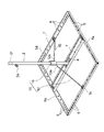
本考案の防護材支持具及び防護柵の実施形態の一例を、図面を参照して説明する。本考案の防護材支持具は、枠状のフレーム1(図1)と、支柱2(図1)と、屋根のハゼ3(図2)に脱着可能な固定具4(図4)を備えている。
(Embodiment)
An example of an embodiment of the protective material support and the protective fence of the present invention will be described with reference to the drawings. The protective material support of the present invention includes a frame-shaped frame 1 (FIG. 1), a support column 2 (FIG. 1), and a fixative 4 (FIG. 4) that can be attached to and detached from the roof goby 3 (FIG. 2). There is.
[フレーム]
図1のフレーム1は、四本の同じ長さのフレーム材5a、5b、5c、5dを正方形に組み合わせ、四隅をネジ止めして枠状にしてある。各フレーム材5a、5b、5c、5dには取り付け孔6が多数開口されている。個々の取り付け孔6は夫々のフレーム材5a、5b、5c、5dの長手方向に細長の長孔である。対向する二辺のフレーム材5a、5bの間には細長の連結具7が配置され、その両端がフレーム材5a、5bにネジ止めして固定してある。取り付け孔6の形状、サイズ、数、間隔等は、使用し易いように設計することができる。
[flame]
In the
フレーム1は二本以上のハゼ3に跨がせることができるサイズであれば、長方形、六角形、八角形、円形、楕円形、その他、任意形状の枠状であってもよい。いずれの形状の場合も、取り付け孔6が開口されている二以上のフレーム材を組み合わせて枠状にする。また、図1の場合と同様に対向するフレーム材の間に連結具7を設ける。
The
[支柱]
支柱2はパイプであり、下端部が固定板8に溶接されており、固定板8を連結具7の長手方向中央部にネジ止めすることにより連結具7の上に立設固定してある。支柱2は二本以上のパイプを縦方向に伸縮可能に連結したものであってもよい。
[Strut]
The
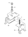
支柱2の上端側には、防護材9を取り付けるための取り付け部2aがある。図3の取り付け部2aはロープ(図2)を通すことができるリングである。取り付け部2aは防護材9が単管パイプやメッシュ材等の場合は、それらを取り付け易い構造にしておく。支柱2の上端にはキャップ21を被せて、支柱2内に雨水や塵芥が入らないようにしてある。
On the upper end side of the
[支持具]
支柱2は支持具10(図1)でフレーム1に支持されている。支持具10は支柱2の外周に設けたパイプ状の嵌合具11と二本の支持材(バー)12を備えている。支持材12はその上端部12aが嵌合具11の外周面対称位置二箇所に溶接により固定され、下端部12bが二辺のフレーム材5c、5dにネジ止めで固定されている。バー12の本数は変更可能であり、例えば、四本にして、夫々のバー12の上端部12aを嵌合具11の外周面四箇所に均等間隔で取り付け、夫々のバー12の下端部12bを嵌合具11の四辺のフレーム材5a、5b、5c、5dにネジ止めで固定することもできる。
[Support]
The
[固定具:ハゼ金具]
固定具4はフレーム1をハゼ3に固定できるものであれば、どのような形状、構造、機能のものであってもよいが、一例としてはハゼ金具4(図4)を使用することができる。
[Fixture: Goby metal fittings]
The
図4のハゼ金具4は金属製の二枚の挟着片16a、16b(図5)を組み合わせてネジ軸17で連結したものであり(図5)、ネジ軸17に螺合されている締め付けナット18を緩めると二枚の挟着片16a、16bの下部を手動で左右(図4の矢印A-B方向)に開閉することができ、締め付けナット18を締め付けると二枚の挟着片16a、16bが開閉できないようにしてある。
The
図4のハゼ金具4は図6のように、ネジ軸17をフレーム1の下から取り付け孔6に差し込んで、ネジ軸17の上部17aをフレーム1の上方まで突出させ、上部17aにフレーム1の上から固定ナット19を螺合することにより、フレーム1の下に取り付けることができる。図3では固定具4をフレーム材5c、5dの夫々の両端に一個ずつ取り付けてあるが、固定具4はハゼ3に取り付け易い任意数と数とすることができる。フレーム1への固定具4の取り付け箇所も任意箇所とすることができる。
In the goby metal fitting 4 of FIG. 4, as shown in FIG. 6, the
[本考案の防護材支持具の使用例]
本考案の防護材支持具をハゼ3に取り付けるには、例えば、次のようにすることができる。
(1)図4のハゼ金具4をハゼ3に取り付ける。この場合、固定具4のネジ軸17に螺合されている締め付けナット18を緩めて、二枚の挟着片16a、16bの下部を手動で左右(図4の矢印A-B方向)に広げる。広げた両挟着片16a、16bをハゼ3の幅方向外側にセットしてハゼ3をその幅方向両外側から挟む。その状態で、ネジ軸17に螺合されている締め付けナット18を締め付けて、二枚の挟着片16a、16bでハゼ3をその両外側から挟着固定する。同様の操作でハゼ金具4をハゼ3の数箇所(例えば、四箇所)に取り付ける。
(2)ハゼ3に挟着固定したハゼ金具4の上に、フレーム1を取り付ける。この場合、ハゼ金具4の上にフレーム1を載せて、図6のように、フレーム1の取り付け孔6を固定具4のネジ軸17に被せ、ネジ軸17の上部17aをフレーム1の上方まで突出させる。フレーム1の上から、ネジ軸17の上部17aに固定ナット19を螺合して締め付けて、フレーム1の下にハゼ金具4を取り付ける。
(3)ハゼ3の数箇所(例えば、四箇所)に取り付けたハゼ金具4の上に、前記(2)の操作によりフレーム1を載せて、ハゼ金具4をフレーム1の下に取り付ける。
(4)前記(1)(2)の操作により、ハゼ3に取り付けた防護材支持具の支柱2の取り付け部(リング)2aにロープ(防護材)9を通して防護柵とする。ロープに代えて、単管パイプやメッシュ材等の他の防護材を支柱2に汎用の単管クランプ、その他の治具で取り付けることができる。防護材支持具を屋根の周囲数箇所に設置し、それら防護材支持具に防護材9を連結することにより、屋根の周囲を防護柵で囲うことができる。
[Example of use of the protective material support of the present invention]
To attach the protective material support of the present invention to the
(1) Attach the goby metal fitting 4 of FIG. 4 to the
(2) The
(3) The
(4) By the operation of (1) and (2) above, the rope (protective material) 9 is passed through the attachment portion (ring) 2a of the
ハゼ3に取り付けた防護材支持具は、常時設置しておくこともできるが、必要時に屋根の上に設置することもできる。
The protective material support attached to the
[固定具の他例]
固定具4はハゼ3に固定可能であれば前記ハゼ金具4以外の構造、形状のものであってもよい。例えば、ハゼ3の長手方向に細長いもの、他の開閉構造のもの、或いは固定具4をハゼ3の上に載せて強く押し付けると挟着片が自動的に開閉して、挟着片によりハゼ3の幅方向両外側を挟着保持できるようにした自動開閉式のもの等であってもよい。自動開閉式の場合は、例えば、二枚の挟着片16a、16bの間に、両挟着片を常時引き寄せるスプリングを設けておき、ハゼ3の上に載せた固定具4をハゼ3に強く押し付けると、スプリングが伸びて二枚の挟着片16a、16bが開き、ハゼ3の幅方向両外側まで開くと、二枚の挟着片16a、16bがスプリング(図示せず)により自動的に引き寄せられて、ハゼ3の幅方向両外側を挟着保持できるようにすることもできる。
[Other examples of fixtures]
The
前記した固定具(ハゼ金具)4はフレーム1の底面に取り付けてあるため、フレーム1の下に隠れている。このため、ハゼ3に取り付ける場合は、前記使用例に記載したように、フレーム1とは別にしてハゼ3に取り付け、そのハゼ金具4の上にフレーム1を載せて、フレーム1の底面にネジ止めすることになる。本考案では、固定具4を枠状のフレーム1の横幅方向外側又は内側に突出させてフレーム1に取り付けて、フレーム1の下に隠れないようにすることもできる。この場合は、フレーム1に取り付けた固定具4をハゼ3の上に載せ、固定具4を手動で開閉操作してハゼ3に取り付けることができる。固定具4が自動開閉式のものである場合は、固定具4をフレーム1に取り付けたままハゼ3の上に載せ、そのまま強く押し付けることにより、固定具4をハゼ3に取り付けることができる。
Since the fixing tool (goby metal fitting) 4 described above is attached to the bottom surface of the
前記した実施形態は本考案の防護材支持具及び防護柵の一例である。本考案の防護材支持具及び防護柵は、ハゼの上に容易且つ確実に取り付けることができるものであれば、本考案の課題を解決できる範囲で設計変更可能である。 The above-described embodiment is an example of the protective material support and the protective fence of the present invention. The protective material support and the protective fence of the present invention can be redesigned to the extent that the problems of the present invention can be solved as long as they can be easily and surely mounted on the goby.
1 フレーム
2 支柱
2a (支柱の)取り付け部
3 ハゼ
4 固定具(ハゼ金具)
5a、5b、5c、5d フレーム材
6 取り付け孔
7 連結具
8 固定板
9 防護材(ロープ)
10 支持具
11 嵌合具
12 支持材(バー)
12a (バーの)上端部
12b (バーの)下端部
16a、16b 挟着片
17 ネジ軸
17a (ネジ軸の)上部
18 締め付けナット
19 固定ナット
21 キャップ
1
5a, 5b, 5c,
10
12a (bar) upper end 12b (bar)
Claims (9)
二本以上のハゼの上に跨がせて設置できる広さの枠状のフレームと、ハゼに脱着可能な固定具と、防護材を取り付け可能な支柱を備えており、
フレームには固定具を取り付け可能な取り付け孔があり、
固定具はフレームの下に固定又は脱着可能に取り付けられており、
支柱はフレームに縦向きに立設されている、
ことを特徴とする防護材支持具。 It is a protective material support that can be fixed to the goby on the roof and installed on the roof.
It is equipped with a frame-shaped frame that can be installed over two or more gobies, a fixative that can be attached to and detached from the goby, and a support that can be attached with a protective material.
The frame has mounting holes for mounting fixtures
Fixtures are fixed or removable under the frame and are removable.
The stanchions are erected vertically on the frame,
A protective material support that is characterized by that.
フレームが二以上のフレーム材を連結して形成された角形枠状又は丸形枠状である、
ことを特徴とする防護材支持具。 In the protective material support according to claim 1,
The frame is a square frame or a round frame formed by connecting two or more frame materials.
A protective material support that is characterized by that.
固定具が、枠状のフレームの底面の下に、又は枠状のフレームの内側又は外側に取り付けられている、
ことを特徴とする防護材支持具。 In the protective material support according to claim 1 or 2.
Fixtures are attached under the bottom of the frame, or inside or outside the frame.
A protective material support that is characterized by that.
支柱がフレームに縦向きに立設され、支持具によりフレームに支持されている、
ことを特徴とする防護材支持具。 The protective material support according to any one of claims 1 to 3.
The stanchions are erected vertically on the frame and are supported by the frame by the support.
A protective material support that is characterized by that.
取り付け孔がフレーム材の長手方向に間隔をあけて二以上開口されており、
前記取り付け孔のいずれかに固定具を付け替え可能である、
ことを特徴とする防護材支持具。 The protective material support according to any one of claims 1 to 4.
Two or more mounting holes are opened at intervals in the longitudinal direction of the frame material.
Fixtures can be replaced in any of the mounting holes,
A protective material support that is characterized by that.
フレームの内側に連結具があり、
支柱が前記連結具に立設固定されている、
ことを特徴とする防護材支持具。 The protective material support according to any one of claims 1 to 5.
There is a connector inside the frame,
The strut is erected and fixed to the connector,
A protective material support that is characterized by that.
固定具が二枚の挟着片を開閉可能に備え、開閉操作によりハゼに固定可能なハゼ金具である、
ことを特徴とする防護材支持具。 The protective material support according to any one of claims 1 to 6.
The fixture is a goby metal fitting that can open and close two sandwich pieces and can be fixed to the goby by opening and closing.
A protective material support that is characterized by that.
固定具が二枚の挟着片を開閉可能に備え、フレームをハゼの上に載せてハゼに強く押し付けると二枚の挟着片が自動的に開閉してハゼに固定可能なものである、
ことを特徴とする防護材支持具。 The protective material support according to any one of claims 1 to 7.
The fixture is equipped with two sandwich pieces that can be opened and closed, and when the frame is placed on the goby and pressed strongly against the goby, the two sandwich pieces automatically open and close and can be fixed to the goby.
A protective material support that is characterized by that.
屋根の二本以上のハゼに、請求項1から請求項8のいずれか1項に記載の防護材支持具の固定具が取り付けられ、それら固定具の上に前記防護材支持具のフレームが固定されることにより、当該フレームがハゼの上に設置固定されて、前記防護材支持具の支柱がフレームの上に立設され、
屋根のハゼに固定された二以上の前記防護材支持具の支柱間に防護材を取り付けた、
ことを特徴とする防護柵。 It is a guard fence attached to the roof goby,
The fixture of the protective material support according to any one of claims 1 to 8 is attached to two or more gobies on the roof, and the frame of the protective material support is fixed on the fixture. By doing so, the frame is installed and fixed on the goby, and the support column of the protective material support is erected on the frame.
A protective material was attached between the columns of the two or more protective material supports fixed to the roof goby.
A guard rail that is characterized by that.
Priority Applications (1)
| Application Number | Priority Date | Filing Date | Title |
|---|---|---|---|
| JP2022000419U JP3237100U (en) | 2022-02-14 | 2022-02-14 | Protective material support and guard fence |
Applications Claiming Priority (1)
| Application Number | Priority Date | Filing Date | Title |
|---|---|---|---|
| JP2022000419U JP3237100U (en) | 2022-02-14 | 2022-02-14 | Protective material support and guard fence |
Publications (1)
| Publication Number | Publication Date |
|---|---|
| JP3237100U true JP3237100U (en) | 2022-04-14 |
Family
ID=81079767
Family Applications (1)
| Application Number | Title | Priority Date | Filing Date |
|---|---|---|---|
| JP2022000419U Active JP3237100U (en) | 2022-02-14 | 2022-02-14 | Protective material support and guard fence |
Country Status (1)
| Country | Link |
|---|---|
| JP (1) | JP3237100U (en) |
-
2022
- 2022-02-14 JP JP2022000419U patent/JP3237100U/en active Active
Similar Documents
| Publication | Publication Date | Title |
|---|---|---|
| US20180283022A1 (en) | Reconfigurable stanchion and guardrail system | |
| JP2011246896A (en) | Installation device for on-roof installation object | |
| JP4716948B2 (en) | Safety rope support bracket | |
| JP2011106174A (en) | Fixing implement for balustrade wall | |
| JP3237100U (en) | Protective material support and guard fence | |
| JP4056548B1 (en) | Safety belt attachment | |
| US9447601B2 (en) | Portable environmental containment unit | |
| JP3150645U (en) | Safety belt support pole for scaffolding | |
| GB2291920A (en) | Safety rail mounting | |
| JP2012012778A (en) | Attaching frame for solar panel | |
| JP2016116264A (en) | Photovoltaic power generation panel pedestal | |
| KR101757279B1 (en) | Building scaffolding equipment by way of wire rope in the boiler system | |
| KR200378274Y1 (en) | Assembly for holding props | |
| KR20150053735A (en) | The vertical pillar unit of prefabricated construction materials | |
| JP6976076B2 (en) | Fixing device and panel structure | |
| KR20160003751U (en) | Lifeline mounting pole | |
| JP5878881B2 (en) | Guard fence and its construction method | |
| KR101757282B1 (en) | Topside load support structure of scaffolding by way of rope in boiler system including wire clamp clamping outside of wire rope when load increased | |
| JP3184052U (en) | Handrail mounting bracket | |
| KR20150010900A (en) | Sockets for construction materials support including cast and system support using thereof | |
| JP7486137B1 (en) | Roof installation and structure | |
| JPH084316A (en) | Pole bearing device | |
| JPH09296632A (en) | Coupling device of metal lattice panel | |
| JP2018040466A (en) | Gas bomb fixture | |
| JPS5912352Y2 (en) | construction scaffolding equipment |
Legal Events
| Date | Code | Title | Description |
|---|---|---|---|
| A80 | Written request to apply exceptions to lack of novelty of invention |
Free format text: JAPANESE INTERMEDIATE CODE: A80 Effective date: 20220224 |
|
| R150 | Certificate of patent or registration of utility model |
Ref document number: 3237100 Country of ref document: JP Free format text: JAPANESE INTERMEDIATE CODE: R150 |