JP3231663U - Press sandwich maker - Google Patents
Press sandwich maker Download PDFInfo
- Publication number
- JP3231663U JP3231663U JP2020005193U JP2020005193U JP3231663U JP 3231663 U JP3231663 U JP 3231663U JP 2020005193 U JP2020005193 U JP 2020005193U JP 2020005193 U JP2020005193 U JP 2020005193U JP 3231663 U JP3231663 U JP 3231663U
- Authority
- JP
- Japan
- Prior art keywords
- tray
- hot press
- main body
- drive mechanism
- press
- Prior art date
- Legal status (The legal status is an assumption and is not a legal conclusion. Google has not performed a legal analysis and makes no representation as to the accuracy of the status listed.)
- Active
Links
Images

Classifications
-
- A—HUMAN NECESSITIES
- A47—FURNITURE; DOMESTIC ARTICLES OR APPLIANCES; COFFEE MILLS; SPICE MILLS; SUCTION CLEANERS IN GENERAL
- A47J—KITCHEN EQUIPMENT; COFFEE MILLS; SPICE MILLS; APPARATUS FOR MAKING BEVERAGES
- A47J37/00—Baking; Roasting; Grilling; Frying
- A47J37/06—Roasters; Grills; Sandwich grills
- A47J37/0611—Roasters; Grills; Sandwich grills the food being cooked between two heating plates, e.g. waffle-irons
-
- A—HUMAN NECESSITIES
- A47—FURNITURE; DOMESTIC ARTICLES OR APPLIANCES; COFFEE MILLS; SPICE MILLS; SUCTION CLEANERS IN GENERAL
- A47J—KITCHEN EQUIPMENT; COFFEE MILLS; SPICE MILLS; APPARATUS FOR MAKING BEVERAGES
- A47J37/00—Baking; Roasting; Grilling; Frying
- A47J37/06—Roasters; Grills; Sandwich grills
- A47J37/0623—Small-size cooking ovens, i.e. defining an at least partially closed cooking cavity
- A47J37/0629—Small-size cooking ovens, i.e. defining an at least partially closed cooking cavity with electric heating elements
Landscapes
- Engineering & Computer Science (AREA)
- Food Science & Technology (AREA)
- Food-Manufacturing Devices (AREA)
- Seeds, Soups, And Other Foods (AREA)
- Baking, Grill, Roasting (AREA)
- Life Sciences & Earth Sciences (AREA)
- Press Drives And Press Lines (AREA)
Abstract
【課題】サンドイッチの食材を均一に焼くことができると共に食材の破片が飛び散りにくいプレスサンドメーカーを提供する。【解決手段】プレスサンドメーカーは、本体1と、トレイ2と、ホットプレス機構と、第1の駆動機構と、破片受け構造を備える。本体の前側には本体の内部に連通した導入口12が設けられ、トレイは導入口を介して本体に出し入れされ、ホットプレス機構は、トレイの上側に位置するホットプレス上型と、トレイの下側に位置するホットプレス下型を備え、ホットプレス上型と前記ホットプレス下型はそれぞれトレイを挟み又は遠ざかるように移動することができ、第1の駆動機構は、ホットプレス上型とホットプレス下型を互いに接近又は分離させるように駆動され、破片受け構造は本体の前側であってトレイの下側に位置するように設けられ、且つ、トレイを引き抜いた状態のときにトレイから落下する食材の残留物を受け取るように用いられる。【選択図】図1PROBLEM TO BE SOLVED: To provide a press sand maker capable of uniformly baking sandwich ingredients and preventing fragments of the ingredients from scattering. A press sand maker includes a main body 1, a tray 2, a hot press mechanism, a first drive mechanism, and a debris receiving structure. An introduction port 12 communicating with the inside of the main body is provided on the front side of the main body, the tray is taken in and out of the main body through the introduction port, and the hot press mechanism is a hot press upper mold located on the upper side of the tray and a lower part of the tray. It has a hot press lower die located on the side, and the hot press upper die and the hot press lower die can be moved so as to sandwich or move away from the tray, respectively, and the first drive mechanism is the hot press upper die and the hot press. Foodstuffs that are driven so that the lower molds approach or separate from each other, the debris receiving structure is provided so as to be located on the front side of the main body and below the tray, and the food material falls from the tray when the tray is pulled out. Used to receive the residue of. [Selection diagram] Fig. 1
Description
本考案は食品加工に用いられるプレスサンドメーカーに関し、特に、サンドイッチの食材を均一に焼くことができるプレスサンドメーカーに関する。 The present invention relates to a press sand maker used for food processing, and more particularly to a press sand maker capable of uniformly baking sandwich ingredients.
生活水準の向上と生活リズム変化に伴い、人々は朝食に栄養面のみならず手軽さをも求めている。ここで、プレスサンドメーカーは、調理の手間を少なくできる朝食用調理器具の一種である。また、プレスサンドメーカーは、サンドイッチの材料をプレスしながら焼く(以下、「ホットプレス」ともいう。)ことにより、手軽に焼いたサンドイッチを作れ、多くの人々に利用されている。 With the improvement of living standards and changes in living rhythms, people demand not only nutritional aspects but also convenience in breakfast. Here, the press sandwich maker is a kind of cooking utensil for breakfast that can reduce the labor of cooking. In addition, a press sandwich maker can easily make a baked sandwich by baking the sandwich material while pressing it (hereinafter, also referred to as "hot press"), and it is used by many people.
ここで、プレスサンドメーカーは手動で加圧しながら焼くものが主流だが、以下の問題がある。すなわち、具体的には、従来のプレスサンドメーカーは上型と下型とをヒンジで接続し、サンドイッチの材料をホットプレス下型に入れた後、ホットプレス上型を手動で裏返すことにより、サンドイッチの材料を詰め込んでから焼き始める必要がある。 Here, the mainstream of press sandwich makers is to bake while manually pressurizing, but there are the following problems. That is, specifically, in a conventional press sand maker, the upper mold and the lower mold are connected by a hinge, the sandwich material is put into the hot press lower mold, and then the hot press upper mold is manually turned over to sandwich the sandwich. It is necessary to stuff the ingredients and then start baking.
しかし、上型は一定の重量があるため、ホットプレス上型を裏返すのは容易ではない。また、厚手のサンドイッチの材料をホットプレスする場合、上型と下型が両端でヒンジによって結合しているため、裏返した後でも、上型と下型の延伸方向が互いに平行とならずに、ホットプレス上型がホットプレス下型に対して傾いてしまう場合がある。 However, since the upper mold has a certain weight, it is not easy to turn over the hot press upper mold. Also, when hot-pressing a thick sandwich material, the upper and lower dies are hinged at both ends, so even after turning over, the stretching directions of the upper and lower dies are not parallel to each other. The upper mold of the hot press may tilt with respect to the lower mold of the hot press.
しかし、このように両者の間に角度がついてしまうと、上型と下型でしっかりと挟まれている箇所はサンドイッチの食材をしっかり焼くことができるものの、ヒンジから離れた場所等の特定の箇所には隙間ができてしまう場合があり、この結果、全体的に満遍なく食材を加熱することが困難であった。 However, if there is an angle between the two in this way, the sandwich ingredients can be baked firmly in the place where the upper and lower molds are firmly sandwiched, but in a specific place such as a place away from the hinge. There may be gaps in the food, and as a result, it is difficult to heat the food evenly.
また、ユーザーがサンドイッチの材料を下型に入れたり取り出したりすると、サンドイッチの材料が下型に接触し、サンドイッチの材料の破片等がプレスサンドメーカーの周囲にこぼれ落ちる場合があり、その後にユーザーによって周囲を掃除しなければならなかった。 Also, when the user puts or removes the sandwich material into or out of the lower mold, the sandwich material may come into contact with the lower mold and debris of the sandwich material may spill around the press sand maker, and then by the user. I had to clean the surroundings.
このような問題に鑑みて、本考案は、サンドイッチの食材を均一に焼くことができると共に食材の破片が飛び散りにくいプレスサンドメーカーを提供することを目的とする。 In view of these problems, it is an object of the present invention to provide a press sand maker capable of uniformly baking sandwich ingredients and preventing the fragments of the ingredients from scattering.
このような問題に鑑みて本考案は以下の構成を備える。 In view of such a problem, the present invention has the following configurations.
本体と、トレイと、ホットプレス機構と、第1の駆動機構と、破片受け構造を備えたプレスサンドメーカーであって、
前記本体の前側には前記本体の内部に連通した導入口が設けられ、
前記トレイは前記導入口を介して前記本体に出し入れされ、
前記ホットプレス機構は、前記トレイの上側に位置するホットプレス上型と、前記トレイの下側に位置するホットプレス下型を備え、
前記ホットプレス上型と前記ホットプレス下型はそれぞれ前記トレイを挟み込み、又は前記トレイから遠ざかるように移動することができ、
前記第1の駆動機構は、前記ホットプレス上型と前記ホットプレス下型を互いに接近させ又は分離させるように駆動するのに用いられ、
前記破片受け構造は前記本体の前側であって前記トレイの下側に位置するように設けられ、且つ、前記トレイを引き抜いた状態のときに前記トレイから落下する食材の残留物を受け取るように用いられる。
A press sandwich maker equipped with a main body, a tray, a hot press mechanism, a first drive mechanism, and a debris receiving structure.
An introduction port communicating with the inside of the main body is provided on the front side of the main body.
The tray is taken in and out of the main body through the introduction port, and is put in and out of the main body.
The hot press mechanism includes a hot press upper mold located on the upper side of the tray and a hot press lower mold located on the lower side of the tray.
The hot press upper mold and the hot press lower mold can each be moved so as to sandwich the tray or move away from the tray.
The first drive mechanism is used to drive the hot press upper mold and the hot press lower mold so as to approach or separate from each other.
The debris receiving structure is provided so as to be located on the front side of the main body and below the tray, and is used to receive the residue of foodstuffs that fall from the tray when the tray is pulled out. Be done.
本考案によるプレスサンドメーカーは以下の効果を奏する。すなわち、本考案によるプレスサンドメーカーは、トレイに乗せられたサンドイッチの材料を下から支持した状態で、本体の内部に食材を出し入れできる。 The press sandwich maker according to the present invention has the following effects. That is, the press sand maker according to the present invention can put the ingredients in and out of the main body while supporting the sandwich material placed on the tray from below.
プレスサンドメーカーを駆動する第1の駆動機構を利用して、上型と下型が互いに近づくように閉じることにより、サンドイッチの材料を上下両面から手動によらずプレスして加熱することができる。 By using the first drive mechanism that drives the press sand maker and closing the upper mold and the lower mold so as to approach each other, the sandwich material can be pressed and heated from both the upper and lower sides without manual operation.
このように、本考案によれば、上型と下型を近づけた際に、ホットプレス上型がホットプレス下型に対して傾きにくく、サンドイッチの材料を上下方向の両側から均一に焼くことができる。 As described above, according to the present invention, when the upper mold and the lower mold are brought close to each other, the hot press upper mold is less likely to tilt with respect to the hot press lower mold, and the sandwich material can be uniformly baked from both sides in the vertical direction. it can.
また、本体前面に破片受け構造を設けているので、トレイ上の食材から生ずる食材の破片は基本的には破片受け構造によって回収することができ、手間もかかりにくい。 Further, since the debris receiving structure is provided on the front surface of the main body, the debris of the food material generated from the food material on the tray can be basically collected by the debris receiving structure, and it is not troublesome.
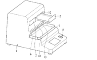
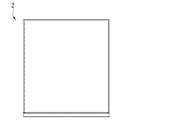
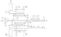
図1〜図4、及び図6を参照して本考案によるプレスサンドメーカーを説明する。ここで、図1は本考案の斜視図である。また、図2は本考案によるスラグトレイを引き出した状態を説明する斜視図である。そして、図3は本考案の要部斜視図であり、図4は第1の駆動機構4とホットプレス機構3の関係を説明する図である。
The press sandwich maker according to the present invention will be described with reference to FIGS. 1 to 4 and 6. Here, FIG. 1 is a perspective view of the present invention. Further, FIG. 2 is a perspective view illustrating a state in which the slag tray according to the present invention is pulled out. FIG. 3 is a perspective view of a main part of the present invention, and FIG. 4 is a diagram for explaining the relationship between the
本考案の実施形態によるプレスサンドメーカーは、図1に示すように、本体1と、この本体1の内部に出し入れ可能であり図1、図6に示すように略平板状に形成されたトレイ2が設けられる。
As shown in FIG. 1, the press sandwich maker according to the embodiment of the present invention can be taken in and out of the main body 1 and the inside of the main body 1, and the
また、トレイ2を水平方向へ移動させることにより、本体1への出し入れを可能とするために、本実施形態によるプレスサンドメーカーは図3にて詳細に説明する第2の駆動機構5を備える。
Further, in order to allow the
図1、図2に示すように、本体1の前面には、本体1の内部と連通すると共に矩形状に形成された導入口12が設けられる。また、トレイ2は導入口12を介して本体1の内部と外部との間で出し入れできる。
As shown in FIGS. 1 and 2, an
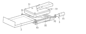
次に、図3を参照してホットプレス機構3の構造を説明する。ホットプレス機構3は、トレイ2の上側と下側にそれぞれ配置されたホットプレス上型31とホットプレス下型32を備える。ここで、ホットプレス上型31とホットプレス下型32は、いずれも熱を伝達し得る加熱管等を備えた加熱部33を備える。
Next, the structure of the hot press mechanism 3 will be described with reference to FIG. The hot press mechanism 3 includes a hot press
ホットプレス上型31とホットプレス下型32は、それぞれトレイ2に対して近づくように移動することができ、両者でトレイ2を挟み込むような位置に移動し得る。また、ホットプレス上型31とホットプレス下型32は、このようなトレイ2を上下から挟み込んだ状態から、いずれもトレイ2から離れる方向へ移動することもでき、トレイ2を基準として接近動作と離間動作を繰り返すことができる。
The hot press
なお、図3にはトレイ2を水平方向に移動させるための第2の駆動機構5も記載されているが、第2の駆動機構5の動作説明は後述する図7〜図9にて行う。
Although FIG. 3 also shows a
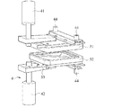
また、本考案によるプレスサンドメーカーは、図4に示すように第1の駆動機構4を備える。第1の駆動機構4は、ホットプレス上型31とホットプレス下型32を互いに近づけ又は分離するように駆動できる。すなわち、第1の駆動機構4は、ホットプレス上型31とホットプレス下型32を垂直方向に移動させるための構造である。
Further, the press sand maker according to the present invention includes the
再び図1に戻り説明する。破片受け構造(符号なし)は、本体1の前面に設けられ、且つトレイ2の下側に配置される。このため、トレイ2を前側に移動させてトレイ2を引き出したとき、その下には破片受け構造が位置することとなる。そのため、破片受け構造は、トレイ2を引き出した際に落下する材料の破片を回収することができる。なお、破片受け構造は材料トレイ7とスラグトレイ6である。
The explanation will be given by returning to FIG. The debris receiving structure (unsigned) is provided on the front surface of the main body 1 and is arranged on the lower side of the
このように、本考案によれば、従来のプレスサンドメーカーと比較して、トレイ2がサンドイッチの材料を下から支持し、トレイ2を本体1の内部に入れることができ、また、トレイ2を本体1の外部へ引き出すこともできる。
As described above, according to the present invention, as compared with the conventional press sand maker, the
そして、図4に示すように、第1の駆動機構4でホットプレス機構3を駆動すると共に、金型であり且つ加熱できるホットプレス上型31とホットプレス下型32を、それぞれ上下方向からトレイ2を挟み込むように移動させることにより、サンドイッチの材料を上下両面からプレスしながら加熱することができるので、ホットプレス下型32に対してホットプレス上型31が傾斜しにくく、サンドイッチの食材を満遍なく焼き上げることができる。
Then, as shown in FIG. 4, the hot press mechanism 3 is driven by the
また、従来と異なりホットプレス上型31を手動で操作する必要がなく、本体1の前面に破片受け構造を採用したので、トレイ2からこぼれ難く、ユーザーの掃除の手間を軽減できる。
Further, unlike the conventional case, it is not necessary to manually operate the hot press
また、トレイ2からこぼれ落ちる食材の切れ端や破片を破片受け構造で回収でき、周囲に散乱しにくいので衛生面からも優れる。
In addition, the pieces and debris of the food spilling from the
また、図1の実施形態によれば、破片受け構造は、例えば本体1の前面に接続された材料トレイ7であり、破片受け構造は構造が簡単なので洗浄し易い。 Further, according to the embodiment of FIG. 1, the debris receiving structure is, for example, a material tray 7 connected to the front surface of the main body 1, and the debris receiving structure has a simple structure and is easy to clean.
続いて、図1〜図4を引き続き参照して本考案による実施形態を説明する。図3に示すように、ホットプレス機構3のホットプレス上型31とホットプレス下型32はトレイ2を上下方向から挟むように配置されるが、このトレイ2の下側には、図1に示すように破片受け構造が設けられる。
Subsequently, an embodiment according to the present invention will be described with reference to FIGS. 1 to 4. As shown in FIG. 3, the hot press
また、図1に示すように、本体1の前面にはガイド口13が形成されている。そして、図1、図2に示すようにスラグトレイ6はこのガイド口13を介して本体1の内部と外部の間で出し入れできる。また、このスラグトレイ6は図2に示すように、本体1の前面に設けられると共に、トレイ2の下側であって材料トレイ7の上側に設けられる。
Further, as shown in FIG. 1, a
そして、スラグトレイ6は図2の状態から更に前側に引き出すと、スラグトレイ6のみを本体1から分離することができる。そのため、スラグトレイ6に材料の破片がたまったら、スラグトレイ6を焦げカス等が上に溜まっている状態のまま引き抜き、そのまま水洗いすることができ、衛生的にも優れる。すなわち、図2のように引き出された状態のスラグトレイ6も、破片受け構造として機能することができる。
Then, when the
更に、図2の状態までスラグトレイ6を引き出せば、スラグトレイ6と本体1との結合状態をガイド口13を介して覗き込むことができるので、ユーザーは容易にスラグトレイ6を取り外すことができ、更に取り外して洗浄した後はガイド口13を除きながらスラグトレイ6を取り付けられるので操作性に優れる。
Further, if the
本実施形態では、図1、図2に示すように、スラグトレイ6の外側は、スラグトレイ6自身を本体1の外側に引き出すための、引き出し機構(符号なし)を備えている。ここで引き出し機構は、例えば図1、図2の実施形態ではスラグトレイ6の側面の一部を貫通させることにより形成されたフック部61である。また、フック部61の内部に工具を差し込んでスラグトレイ6を引き出すことができる。
In the present embodiment, as shown in FIGS. 1 and 2, the outside of the
また、他の実施形態としては引き出し機構はフック部61の代わりにハンドル(図示せず)を設けても良い。この場合はフック部61に挿入するための工具が不要となる。本考案の実施形態によれば、引き出し機構を備えるので、ユーザーはスラグトレイ6を引き出し、スラグトレイ6内に溜まった材料の欠片を洗浄することができる。
Further, as another embodiment, the pull-out mechanism may be provided with a handle (not shown) instead of the
また、本実施形態では、トレイ2は、熱伝導性材料で形成されている。このため、ホットプレス構造32は、トレイ2を介してサンドイッチの材料を加熱でき、更に、ホットプレス構造3はホットプレス上型31とホットプレス下型32を使用してサンドイッチの材料に対して上下方向の両側から熱を加えることができる。
Further, in the present embodiment, the
図1と図2を参照して説明する。本実施形態では、導入口12は水平方向に並べて2個設けられ、トレイ2も各導入口12に対応するように2個設けられている。このため、ユーザーは複数のサンドイッチの材料を同時に加熱することができる。
This will be described with reference to FIGS. 1 and 2. In the present embodiment, two
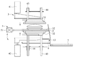
続いて、図4を参照して本考案の実施形態を説明する。本実施形態では、第1の駆動機構4は、上駆動機構41と下駆動機構42に加え、ホットプレス上型31とホットプレス下型32に連結するために用いられるガイドスリーブ44を備える。また、ガイドスリーブ44はホットプレス上型31又は下型に対応するように2個ずつ設けられる。また、上駆動機構41は、ホットプレス上型31を駆動するために使用される。一方、下駆動機構42は、ホットプレス下型32を駆動するために使用される。
Subsequently, an embodiment of the present invention will be described with reference to FIG. In the present embodiment, the
ここで、上駆動機構41と下駆動機構42はねじを用いた駆動機構であっても良く、更には、上駆動機構41と下駆動機構42はプッシュロッド式であっても良い。また、プッシュロッド式の場合には空気圧式のプッシュロッド又は電気式のプッシュロッドで構成することができる。
Here, the
更に、上駆動機構41と下駆動機構42がプッシュロッドである場合、上駆動機構41のシリンダが本体1上に配置されると共に、上駆動機構41の伸縮ロッドの下端がホットプレス上型31の上側に取り付けられることにより駆動力が伝達される。
また、下駆動機構42についても同様であり、下駆動機構42のシリンダを本体1に取り付け、伸縮ロッドの上端をホットプレス下型32の下側に取り付けることにより駆動力を伝達する。
Further, when the
The same applies to the
したがって、上駆動機構41と下駆動機構42は、同一の行程にて、ホットプレス上型31とホットプレス下型32の両者が接近又は離間するように駆動される。このように本考案は、ホットプレス上型31とホットプレス下型32が相対的に傾かず、平行な状態を保ったまま食材をプレスできる。よって、サンドイッチの食材を満遍なく均一に加熱できる。
Therefore, the
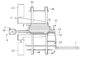
続いて、図7を参照して本考案の実施形態を説明する。ここで、図7はプレスサンドメーカーの内部からトレイを引き出した状態を示す断面図である。 Subsequently, an embodiment of the present invention will be described with reference to FIG. 7. Here, FIG. 7 is a cross-sectional view showing a state in which the tray is pulled out from the inside of the press sand maker.
また、本実施形態において、ガイド機構(符号なし)は、ホットプレス上型31とホットプレス下型32を上下方向に移動させるために用いられる。ここで、ガイド機構は、ホットプレス上型31とホットプレス下型32のそれぞれに対応するように、トレイ2の上側と下側に設けられる。
Further, in the present embodiment, the guide mechanism (unsigned) is used to move the hot press
ガイド機構上下方向からそれぞれ移動させて食材を加圧するための構造である。 Guide mechanism This is a structure for pressurizing food by moving it from the vertical direction.
そして、ガイド機構は、それぞれ本体1に対して高さ方向に延伸するように設けられた棒状のガイドポスト43を備える他、ガイドスリーブ44を備える。
Each of the guide mechanisms includes a rod-shaped guide post 43 provided so as to extend in the height direction with respect to the main body 1, and also includes a
ここで、図7に示すように、上側のガイドポスト43は、一端(下側の端部)がホットプレス上型31に接続されており、他端側がガイドスリーブ44に嵌合している。
Here, as shown in FIG. 7, one end (lower end) of the
このように、本実施形態では、ホットプレス上型31とホットプレス下型32は、高さ方向に延伸するガイドポスト43と、これらガイドポストと嵌合するガイドスリーブ44を利用して、トレイ2を挟み込むように上下方向へ互いに接近又は離間できる。
As described above, in the present embodiment, the hot press
また、本実施形態では、ガイド機構と第1の駆動機構4は、それぞれ、ホットプレス上型31とホットプレス下型32を上下方向から挟み込むことができるよう相対するように配置され、ホットプレス上型31とホットプレス下型32は上下方向に動作することができ、トレイ2に設けられた食材をプレスしながら加熱することができる。
Further, in the present embodiment, the guide mechanism and the
再び図3を参照して説明する。本実施形態では、第2の駆動機構5を更に含み、第2の駆動機構5は、トレイ2を導入口12を介して本体1の内部に搬入し、又は本体1の外側へ搬出するように駆動される。
This will be described again with reference to FIG. In the present embodiment, the
第2の駆動機構5は、トレイ2の後側に設けられ、第2の駆動機構5の他方の側は、ガイド構造(符号なし)を介して本体1に接続される。ここで、ガイド構造は、トレイ2の移動方向に沿って設けられたガイドロッド(図7のトレイ2の下側)および可動スリーブ55(図3参照)を含む。
The
第2の駆動機構5は、トレイ2の一方の側に配置され、トレイ2が本体1の内部に完全に収容されると、トレイ2の図3において一番右側に位置する端部はガイド構造を介して本体1に当接する。
The
また、第2の駆動機構5は、図3に示す第2の駆動装置51、伝達ロッド52と、伝達ナット53を備える。第2の駆動装置51は、伝達ロッド52を回転駆動できるように接続されたモーターであり、第2の駆動装置51は、好ましくは、サーボモーターである。サーボモーターは制御精度が高いので、トレイ2の移動制御の精度も高くすることができる。伝達ロッド52と伝達ナット53とは、伝達ロッド52が回転可能に連接されている。
Further, the
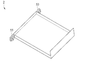
図3に示すように、トレイ2は伝達ナット53に接続され、ガイド構造は、図7に示すようにトレイ2を下から支えるように前後方向に延伸するガイドロッド54と、トレイ2の移動方向に沿って配置された可動スリーブ55(図3、図5)とを含む。
As shown in FIG. 3, the
可動スリーブ55は、図7のガイドロッド54にスライド可能に嵌合することができる。また、トレイ2の他端側は可動スリーブ55と連接される。
The
第2の駆動装置51が伝達ロッド52を駆動して回転させることにより、トレイ2を本体1の内部に搬入するか、ガイドロッド54の方向に沿ってトレイ2を本体1の外側へ押し出すように選択可能に移動できる。
The
なお、トレイ2はスクリュードライブモードを採用しており、トレイ2の移動効果は安定している。要するに、伝達ロッド52が回転した回数に応じて移動距離を微調整することができる。
The
本考案による実施形態によれば、トレイ2はユーザーの命令により自動的に本体1の内部に入ことができ、更に本体1の外側に出すこともできるので、本考案によるプレスサンドメーカーは手動でホットプレス上型31を押し付ける必要がなく、ユーザーの負担を軽減できる。
According to the embodiment according to the present invention, the
また、本考案による実施形態では、図1に示すように、2つの導入口12があり、トレイ2は、各導入口12に対応するように2個備えられている。この配置により、ユーザーが複数のサンドイッチの材料を同一の工程で加熱しながらプレスするのに便利である。
Further, in the embodiment according to the present invention, as shown in FIG. 1, there are two
また、本考案によれば、図3に記載した第2の駆動機構5が、図1の2個のトレイ2に対応するように、2系統準備されている(なお、1系統しか図示していない。)。このように、2系統の導入口12と2個のトレイ2を備えているので、ユーザーは複数のサンドイッチの材料を同一の工程で加熱しながらプレスことができる。
Further, according to the present invention, two systems of the
図1、図2を参照して説明する。本実施形態では、図示しない制御モジュールと制御部を備える。制御モジュールは、本体1に設けられた制御回路である。制御部は本体1の前側に設けられた操作パネル8である。また、操作パネル8と制御モジュールは電気的に接続されている。 This will be described with reference to FIGS. 1 and 2. In this embodiment, a control module and a control unit (not shown) are provided. The control module is a control circuit provided in the main body 1. The control unit is an operation panel 8 provided on the front side of the main body 1. Further, the operation panel 8 and the control module are electrically connected.
そして、本実施形態のようにトレイ2が電気的に駆動される方式では、制御モジュールは、第1の駆動機構4と第2の駆動機構5に電気的にそれぞれ接続されており、ホットプレス機構3とトレイ2の作動状態を、操作パネル8を介して制御することができる。
Then, in the method in which the
なお、図示を省略しているが、本実施形態では、制御部はコントローラーを備える。ここで、コントローラーはリモートコントローラーであっても良く、ワイヤレスで制御モジュールに接続されている(たとえば、Wi-FiまたはBluetooth(登録商標)経由での接続)。また、制御モジュールは、リモートコントローラーから送信された信号を受信するための受信機能を備える。 Although not shown, in the present embodiment, the control unit includes a controller. Here, the controller may be a remote controller and is wirelessly connected to the control module (eg, connected via Wi-Fi or Bluetooth®). In addition, the control module has a receiving function for receiving a signal transmitted from the remote controller.
トレイ2が電気的に駆動される本実施形態では、制御モジュールはそれぞれ第1の駆動機構4と第2の駆動機構5に電気的に接続される。そして、ホットプレス機構3とトレイ2の作動状態は、コントローラーによって制御することができる。
In this embodiment in which the
次に図7〜図9を参照して本考案の動作を説明する。ユーザーは、操作パネル8を介して第2の駆動機構5を制御して、図7に示すようにトレイ2を駆動して本体1の外側へトレイ2を引き出すように移動させる。
Next, the operation of the present invention will be described with reference to FIGS. 7 to 9. The user controls the
そうすると、図7に示すように、サンドイッチの材料をトレイ2の上に置ける位置までトレイ2を引き出すことができる。
Then, as shown in FIG. 7, the
具体的には、第2の駆動機構5が制御モジュールによって制御され、第2の駆動装置51が、トレイ2を本体1の内部に引き込まれる。
Specifically, the
そして、伝達ナット53に接続されたトレイ2は、伝達ロッド52の回転に伴い本体1の内部へ収容されるように移動する。次に、第1の駆動機構4を介してホットプレス上型31とホットプレス下型32をトレイ2側へ移動させるように制御して、材料を温めながらプレスする。
Then, the
具体的には、図8の状態から図9に示すようにホットプレス上型31を下側へ押し下げるように移動させると共に、ホットプレス下型32を、ホットプレス上型31と共にトレイ2を挟み込むように上向きに移動させる。
Specifically, as shown in FIG. 9, the hot press
すなわち、ホットプレス機構3のホットプレス上型31を押し下げるため、上駆動機構41を駆動して、ガイドポスト43を下側に移動させることにより、ガイドポスト43の他端側に接続されたホットプレス上型31をトレイ2がある下側へ押し下げることができる。
That is, in order to push down the hot press
第1の駆動機構4は、ホットプレス上型31とホットプレス下型32を互いに引き離す方向に制御モジュールからの命令によって駆動する。図7のトレイ2を本体1の外部へ引き出した場合と同様の動作するように、制第2の駆動機構5を駆動して、トレイ2を本体1の外側に移動させて、ホットプレスされたサンドイッチをユーザーに提供する。
このように、本考案は、サンドイッチの食材を均一に焼くことができると共に食材の破片が飛び散りにくいプレスサンドメーカーを提供できる他、以下の効果をも奏する。
The
As described above, the present invention can provide a press sand maker capable of uniformly baking sandwich ingredients and preventing the fragments of the ingredients from scattering, and also has the following effects.
すなわち、破片受け構造は本体1の前面に接続された材料トレイ7又はスラグトレイ6であり、破片受け構造は単純な構造を有するので洗浄に便利である。
That is, the debris receiving structure is a material tray 7 or a
また、本体のトレイ2より下にはスラグトレイ6が備えられ、スラグトレイ6はガイド口13を介して本体1の内部に出し入れできる。
Further, a
このため、スラグトレイ6自体を本体1から個別に取り外すことができ、本体1内部の焦げカス等の残留物を効果的取り除け、衛生的である。
Therefore, the
さらに、ガイド13は開口部であり、この開口部を覗き込むことにより、目視しながらスラグトレイ6を引き出したり、取り付けたりすることがで操作性に優れる。また、スラグトレイ6の外側に形成されたレールは、それごと本体1の外へ取り出せるような構造をしている。
Further, the
また、引き出し機構は、工具で接続できるハンドルまたはフック部61である。このため、ユーザーはスラグトレイ6を引き出し、スラグトレイ6内の破片を掃除するのに便利である。
Further, the pull-out mechanism is a handle or
さらに、トレイ2は熱伝導性材料でできており、このため、ホットプレス上型31、ホットプレス下型32は、トレイ2を介してサンドイッチの食材に熱を伝えられる。
さらに、本体1には2つの導入口12があり、トレイ2は、各導入口12に対応するように2個備えられており、このような構成としたので、ユーザーは、複数のサンドイッチの材料を同時にホットプレスできる。なお、2個のトレイ2を動かすためには第1の駆動機構4と第2の駆動機構5を2系統ずつ準備する。
Further, the
Further, the main body 1 has two
上述の記載と示唆に基づいて、この当業者は、上記の実施形態の内容を適宜変更することができるが、本考案の技術的範囲は当該変更後の考案にも均等の範囲が及ぶものとする。また、本考案の上述の実施形態は本考案の技術的範囲を本明細書の実施形態で説明したものに限定するものではない。 Based on the above description and suggestions, those skilled in the art may appropriately modify the contents of the above embodiments, but the technical scope of the present invention shall be within the same scope as the modified invention. To do. Further, the above-described embodiments of the present invention do not limit the technical scope of the present invention to those described in the embodiments of the present specification.
1 本体
12 導入口
13 ガイド口
2 トレイ
3 ホットプレス機構
31 ホットプレス上型
32 ホットプレス下型
33 加熱部
4 第1の駆動機構
41 上駆動機構
42 下駆動機構
43 ガイドポスト
44 ガイドスリーブ
5 第2の駆動機構
51 第2の駆動装置
52 伝達ロッド
53 伝達ナット
54 ガイドロッド
55 可動スリーブ
6 スラグトレイ
61 フック部
7 材料トレイ
8 制御部
1
Claims (10)
前記本体の前側には前記本体の内部に連通した導入口が設けられ、
前記トレイは前記導入口を介して前記本体に出し入れされ、
前記ホットプレス機構は、前記トレイの上側に位置するホットプレス上型と、前記トレイの下側に位置するホットプレス下型を備え、
前記ホットプレス上型と前記ホットプレス下型はそれぞれ前記トレイを挟み込み、又は前記トレイから遠ざかるように移動することができ、
前記第1の駆動機構は、前記ホットプレス上型と前記ホットプレス下型を互いに接近させ又は分離させるように駆動するのに用いられ、
前記破片受け構造は前記本体の前側であって前記トレイの下側に位置するように設けられ、且つ、前記トレイを引き抜いた状態のときに前記トレイから落下する食材の残留物を受け取るように用いられる、
ことを特徴とするプレスサンドメーカー。 A press sandwich maker equipped with a main body, a tray, a hot press mechanism, a first drive mechanism, and a debris receiving structure.
An introduction port communicating with the inside of the main body is provided on the front side of the main body.
The tray is taken in and out of the main body through the introduction port, and is put in and out of the main body.
The hot press mechanism includes a hot press upper mold located on the upper side of the tray and a hot press lower mold located on the lower side of the tray.
The hot press upper mold and the hot press lower mold can each be moved so as to sandwich the tray or move away from the tray.
The first drive mechanism is used to drive the hot press upper mold and the hot press lower mold so as to approach or separate from each other.
The debris receiving structure is provided so as to be located on the front side of the main body and below the tray, and is used to receive the residue of foodstuffs that fall from the tray when the tray is pulled out. Be,
A press sandwich maker that features that.
ことを特徴とする請求項1に記載のプレスサンドメーカー。 The debris receiving structure is connected to the material tray on the front side of the main body.
The press sandwich maker according to claim 1.
ことを特徴とする請求項1又は2に記載のプレスサンドメーカー。 A slag tray provided in the main body and located below the hot press mechanism is further provided, the main body is provided with a guide port, and the slug tray can be taken in and out of the main body through the guide port.
The press sandwich maker according to claim 1 or 2.
ことを特徴とする請求項3に記載のプレスサンドメーカー。 The guide port is provided on the front side of the main body and is located on the upper side of the material tray.
The press sandwich maker according to claim 3.
ことを特徴とする請求項3に記載のプレスサンドメーカー。 The outside of the slag tray is provided with a pull-out mechanism for pulling out the slag tray itself to the outside of the main body, and the pull-out mechanism is a hook portion that can be connected by using a handle or a tool.
The press sandwich maker according to claim 3.
ことを特徴とする請求項1に記載のプレスサンドメーカー。 A second drive mechanism is further provided, and the second drive mechanism drives the tray so as to move in and out of the main body through the introduction port.
The press sandwich maker according to claim 1.
ことを特徴とする請求項1に記載のプレスサンドメーカー。 The tray is made of a thermally conductive material,
The press sandwich maker according to claim 1.
ことを特徴とする請求項1に記載のプレスサンドメーカー。 The first drive mechanism includes an upper drive mechanism and a lower drive mechanism, the upper drive mechanism is used to drive the hot press upper mold, and the lower drive mechanism is used to drive the hot press lower mold. The upper drive mechanism and the lower drive mechanism used are either screw drive mechanisms, pneumatic push rods, or electric push rods.
The press sandwich maker according to claim 1.
ことを特徴とする請求項1に記載のプレスサンドメーカー。 Two inlets are provided, and two trays are provided corresponding to each inlet.
The press sandwich maker according to claim 1.
ことを特徴とする請求項6に記載のプレスサンドメーカー。 Two introduction ports are provided, two trays are provided so as to correspond to the introduction ports, and two second drive mechanisms are provided so as to correspond to the introduction ports.
The press sandwich maker according to claim 6.
Applications Claiming Priority (2)
| Application Number | Priority Date | Filing Date | Title |
|---|---|---|---|
| TW109213470 | 2020-10-14 | ||
| TW109213470U TWM606927U (en) | 2020-10-14 | 2020-10-14 | Heat press machine for sandwich |
Publications (1)
| Publication Number | Publication Date |
|---|---|
| JP3231663U true JP3231663U (en) | 2021-04-15 |
Family
ID=74211508
Family Applications (1)
| Application Number | Title | Priority Date | Filing Date |
|---|---|---|---|
| JP2020005193U Active JP3231663U (en) | 2020-10-14 | 2020-12-02 | Press sandwich maker |
Country Status (7)
| Country | Link |
|---|---|
| US (1) | US20220110478A1 (en) |
| JP (1) | JP3231663U (en) |
| KR (1) | KR102374349B1 (en) |
| CA (1) | CA3101134C (en) |
| MY (1) | MY204911A (en) |
| PH (1) | PH22020050670U3 (en) |
| TW (1) | TWM606927U (en) |
Families Citing this family (2)
| Publication number | Priority date | Publication date | Assignee | Title |
|---|---|---|---|---|
| CN114135927B (en) * | 2021-11-05 | 2023-06-27 | 华能海南发电股份有限公司东方电厂 | Hot press steam extraction and heat supply control method and system |
| CN117530596B (en) * | 2023-12-14 | 2025-01-03 | 广州祈信金属制品有限公司 | Electronic electrodeless intelligent control multifunctional oven |
Family Cites Families (17)
| Publication number | Priority date | Publication date | Assignee | Title |
|---|---|---|---|---|
| FR2584893B1 (en) * | 1985-07-18 | 1987-11-20 | Itm Entreprises | APPARATUS FOR COOKING FOOD PRODUCTS IN PARTICULAR TO BE CONSUMED WITH BREAD |
| US6588363B1 (en) * | 2000-08-17 | 2003-07-08 | Paul J. Svejkovsky | Seasoning system and method |
| US20040123744A1 (en) * | 2002-12-17 | 2004-07-01 | Bobo Thomas B. | Dual level waffle iron |
| FR2877810B1 (en) * | 2004-11-16 | 2007-02-23 | Tang Freres Sarl | MACHINE FOR MANUFACTURING SANDWICHES |
| KR20060062226A (en) * | 2004-12-03 | 2006-06-12 | 주식회사 대우일렉트로닉스 | Door Drive of Pizza Oven |
| JP4885124B2 (en) * | 2005-03-25 | 2012-02-29 | 北川精機株式会社 | Press machine |
| US7444928B2 (en) * | 2005-05-06 | 2008-11-04 | Delice Co., Ltd. | Apparatus for producing crackers |
| US20090308264A1 (en) * | 2008-06-12 | 2009-12-17 | Gary Lee Estess | Ultimate combo smoker |
| WO2011064264A1 (en) * | 2009-11-24 | 2011-06-03 | Innovic Holding Aps | Foil tray heating device |
| CN105492320A (en) * | 2013-08-23 | 2016-04-13 | B/E航空公司 | Bakeware for aircraft galleys |
| US20150297029A1 (en) * | 2014-04-16 | 2015-10-22 | Spectrum Brands, Inc. | Cooking appliance using thin-film heating element |
| EP3416490A1 (en) * | 2016-02-20 | 2018-12-26 | Miraj Business Development PVT Ltd | An automatic machine for making flat edibles |
| US20190082884A1 (en) * | 2017-09-20 | 2019-03-21 | Jm Posner Ltd | Waffle Makers |
| US20190328175A1 (en) * | 2018-04-27 | 2019-10-31 | Frederic Speed Bancroft | Automated Air Fryer |
| KR101972114B1 (en) * | 2018-08-27 | 2019-04-25 | 주식회사 두리아 | roast apparatus |
| CN210471932U (en) * | 2019-05-30 | 2020-05-08 | 益芳封口机有限公司 | Sandwich Heater |
| TWM607368U (en) * | 2020-08-04 | 2021-02-11 | 統一超商股份有限公司 | Hot press toaster |
-
2020
- 2020-10-14 TW TW109213470U patent/TWM606927U/en unknown
- 2020-11-13 KR KR1020200151547A patent/KR102374349B1/en active Active
- 2020-11-27 CA CA3101134A patent/CA3101134C/en active Active
- 2020-11-27 PH PH2/2020/050670U patent/PH22020050670U3/en unknown
- 2020-11-27 US US17/105,724 patent/US20220110478A1/en not_active Abandoned
- 2020-11-30 MY MYPI2020006314A patent/MY204911A/en unknown
- 2020-12-02 JP JP2020005193U patent/JP3231663U/en active Active
Also Published As
| Publication number | Publication date |
|---|---|
| PH22020050670U1 (en) | 2020-12-18 |
| CA3101134C (en) | 2022-10-18 |
| US20220110478A1 (en) | 2022-04-14 |
| MY204911A (en) | 2024-09-21 |
| TWM606927U (en) | 2021-01-21 |
| PH22020050670U3 (en) | 2021-05-21 |
| CA3101134A1 (en) | 2022-04-14 |
| PH22020050670Y1 (en) | 2020-12-18 |
| KR102374349B1 (en) | 2022-03-14 |
Similar Documents
| Publication | Publication Date | Title |
|---|---|---|
| JP3231663U (en) | Press sandwich maker | |
| CN106235863B (en) | Control panel turning mechanism and cooking utensils | |
| CN1201378A (en) | Toaster with lid for reducing energy consumption | |
| US6561081B2 (en) | Automatic bread slice-toasting oven | |
| KR20040024394A (en) | Microwave oven with toaster | |
| CN101175430B (en) | Combined food cooking device and method | |
| CN104720618A (en) | Electric oven | |
| CN110432797B (en) | Frying and baking machine | |
| US20180338640A1 (en) | Stove | |
| CN218338184U (en) | Electric universal steaming and baking oven used on table top | |
| JP3230711U (en) | Press sandwich maker | |
| CN214104200U (en) | Sandwich hot press | |
| CN216494929U (en) | Oven of inside gridion of pull formula | |
| CN116671533A (en) | Sesame cake oven | |
| CN112386075B (en) | A meal catering device for student catering and its working method | |
| CN223695666U (en) | Intelligent toast machine | |
| CN223731254U (en) | Heating device with lifting function and oven | |
| CN223695655U (en) | Oven with adjustable cooking space | |
| CN223695657U (en) | Multi-functional oven | |
| CN223695654U (en) | Oven drawer with heating device and liftable heating device and oven | |
| CN2624087Y (en) | Microwave oven with baking oven | |
| CN217827589U (en) | Multifunctional air frying and roasting device | |
| CN107969929A (en) | A kind of baking tray and application have the roasting plant of the baking tray | |
| CN106724929B (en) | Frying and roasting equipment convenient for oil leakage | |
| CN216167003U (en) | Smokeless rotary steamed bun baking equipment |
Legal Events
| Date | Code | Title | Description |
|---|---|---|---|
| A521 | Request for written amendment filed |
Free format text: JAPANESE INTERMEDIATE CODE: A523 Effective date: 20210210 |
|
| R150 | Certificate of patent or registration of utility model |
Ref document number: 3231663 Country of ref document: JP Free format text: JAPANESE INTERMEDIATE CODE: R150 |
|
| R250 | Receipt of annual fees |
Free format text: JAPANESE INTERMEDIATE CODE: R250 |
|
| R250 | Receipt of annual fees |
Free format text: JAPANESE INTERMEDIATE CODE: R250 |
|
| R250 | Receipt of annual fees |
Free format text: JAPANESE INTERMEDIATE CODE: R250 |