JP3215593U - Portable tape cutter configuration - Google Patents
Portable tape cutter configuration Download PDFInfo
- Publication number
- JP3215593U JP3215593U JP2018000184U JP2018000184U JP3215593U JP 3215593 U JP3215593 U JP 3215593U JP 2018000184 U JP2018000184 U JP 2018000184U JP 2018000184 U JP2018000184 U JP 2018000184U JP 3215593 U JP3215593 U JP 3215593U
- Authority
- JP
- Japan
- Prior art keywords
- cutter
- tape cutter
- tape
- portable tape
- lid
- Prior art date
- Legal status (The legal status is an assumption and is not a legal conclusion. Google has not performed a legal analysis and makes no representation as to the accuracy of the status listed.)
- Active
Links
Images


Abstract
【課題】携帯式テープカッター構成を提供する。【解決手段】携帯式テープカッター構成は、内側空間に主要組立用部材、収容溝及び位置決め用リブが設置される後蓋1と、前記収容溝に装設される弾性部材2と、押し部、押下部、プラットフォーム、孔部、圧縮用バンプ、係合リング及び挟持用スライダーが設置され、前記後蓋に装設され、前記主要組立用部材には前記孔部が貫通させ、前記挟持用スライダーが前記位置決め用リブに着接され、前記圧縮用バンプが前記収容溝前端に位置されるプッシュ用キャリアー3と、中空の回転軸、弧状の当接部及びカッターが設置され、前記回転軸により前記主要組立用部材に装設される回転カッターセット4と、前記係合リングに結合され、テープ先が前記プラットフォームに静置されるテープロール5と、前記後蓋に固定されるように結合される前蓋6とを備える。本考案は開口部及び出口部を有し、前記押し部は前記開口部に位置され、携帯式テープカッター構造が形成される。【選択図】図9A portable tape cutter configuration is provided. A portable tape cutter configuration includes a rear cover 1 in which a main assembly member, an accommodation groove and a positioning rib are installed in an inner space, an elastic member 2 installed in the accommodation groove, a pushing portion, A pressing part, a platform, a hole, a compression bump, an engagement ring, and a holding slider are installed, and are mounted on the rear lid. The hole is passed through the main assembly member, and the holding slider is A push carrier 3 that is attached to the positioning rib and the compression bump is located at the front end of the receiving groove, a hollow rotating shaft, an arc-shaped contact portion, and a cutter are installed. A rotary cutter set 4 mounted on an assembly member, a tape roll 5 coupled to the engagement ring and having a tape tip stationary on the platform, and coupled to be fixed to the rear lid. And a front lid 6 that. The present invention has an opening and an outlet, and the pusher is positioned in the opening to form a portable tape cutter structure. [Selection] Figure 9
Description
本考案は、テープカッター構成に関し、より詳しくは、携帯用テープカッター構成に関する。 The present invention relates to a tape cutter configuration, and more particularly to a portable tape cutter configuration.
従来の卓上型テープカッター構造は、台本体が卓上に置かれ、前記台本体の重量が重い上に前記台本体の底面に滑り止めパッドを有するため、使用者がテープを引いた際に引く力が強すぎて前記台本体が移動してしまう事象が防止され、使用者の作業に影響を及ぼさないようになっている。また、前記台本体には凹型溝を有し、前記凹型溝の両側には装設溝が設けられ、軸心がテープロールに着接された後、前記軸心が2つの前記装設溝に着接され、前記軸心が2つの前記装設溝上で回転を行う。これにより、使用者がテープを引っ張る際に軸心がテープが引かれる方向に追従して回転を行い、使用者がより長いテープを使用可能になる。前記台本体の前端にはカッターを有し、引き出されたテープは前記カッターにより裁断され、使用者が裁断されたテープを物品に貼ることができるようになる。 The conventional tabletop tape cutter structure has a table body placed on the table, the table body is heavy, and has a non-slip pad on the bottom surface of the table body. Is prevented from moving too much, so that the work of the user is not affected. In addition, the base body has concave grooves, and installation grooves are provided on both sides of the concave groove. After the shaft center is attached to the tape roll, the shaft center is formed in the two installation grooves. The shaft is rotated and the shaft rotates on the two installation grooves. Accordingly, when the user pulls the tape, the shaft rotates following the direction in which the tape is pulled, and the user can use a longer tape. A front end of the base body has a cutter, and the drawn tape is cut by the cutter so that the user can attach the cut tape to the article.
他の従来の技術によるコンパクト型テープカッター構造も同様に台本体を有する。但し、使用者が携帯しやすいように前記台本体が軽くなっており、同様に軸心が着接される凹型溝を有し、前記軸心にはテープロールが着接され、カッターが前記台本体の前端に位置され、使用者がテープを裁断後に使用可能になる。 Other prior art compact tape cutter structures have a base body as well. However, the base body is lightened so that it can be easily carried by the user, and has a concave groove to which the shaft center is similarly attached. A tape roll is attached to the shaft center, and the cutter is attached to the base. Located at the front end of the main body, the user can use it after cutting the tape.
しかしながら、前述した従来の技術では、どちらにも本考案者が改善を目指す多くの欠点が存在する。従来の卓上型テープカッターは片手でテープの裁断作業を行えるが、体積が大きく、重量も重いため、使用者は携帯できなかった。また、コンパクト型テープカッターは前記台本体が軽量であり、体積も小さいため、使用者が携帯可能であるが、使用時にテーブルに置いて使用できないため、使用者は両手を使わなければならず、片手で前記台本体を掴み、もう片方の手でテープを前記カッターの箇所まで引っ張って裁断を行わねばならない。ゆえに、両方の利点を兼ね備えたテープカッター構造は存在せず、使用者が携帯可能であり、片手でテープの裁断作業を行える構造が望まれた。 However, both of the conventional techniques described above have many drawbacks that the inventor aims to improve. A conventional desktop tape cutter can cut the tape with one hand, but it is large in volume and heavy, so the user cannot carry it. In addition, the compact tape cutter is lightweight and has a small volume, so it can be carried by the user, but it cannot be placed on the table when used, so the user must use both hands, Cutting must be done by holding the base body with one hand and pulling the tape to the cutter with the other hand. Therefore, there is no tape cutter structure that has both advantages, and a structure that can be carried by the user and that can cut the tape with one hand is desired.
そこで、本考案者は上記の欠点が改善可能と考え、鋭意検討を重ねた結果、合理的設計で上記の課題を効果的に改善する本考案の提案に到った。 Therefore, the present inventor considered that the above-described drawbacks can be improved, and as a result of intensive studies, the present inventor has arrived at a proposal of the present invention that effectively improves the above-described problems with a rational design.
本考案は、このような従来の問題に鑑みてなされたものである。上記課題解決のため、本考案は、携帯用テープカッター構成を提供することを主目的とする。 The present invention has been made in view of such conventional problems. In order to solve the above-described problems, the present invention mainly aims to provide a portable tape cutter configuration.
上述した課題を解決し、目的を達成するために、本考案に係る携帯用テープカッター構成の特徴は、内側空間に主要組立用部材、収容溝及び位置決め用リブが設置される後蓋と、前記収容溝に装設される弾性部材と、押し部、押下部、プラットフォーム、孔部、圧縮用バンプ、係合リング及び挟持用スライダーが設置され、前記後蓋に装設され、前記主要組立用部材には前記孔部が貫通させ、前記挟持用スライダーが前記位置決め用リブに着接され、前記圧縮用バンプが前記収容溝前端に位置されるプッシュ用キャリアーと、中空の回転軸、弧状の当接部及びカッターが設置され、前記回転軸により前記主要組立用部材に装設される回転カッターセットと、前記係合リングに結合され、テープ先が前記プラットフォームに静置されるテープロールと、前記後蓋に固定されるように結合される前蓋とを備える。本考案は開口部及び出口部を有し、前記押し部は前記開口部に位置され、携帯式テープカッター構造が形成される。 In order to solve the above-described problems and achieve the object, the features of the portable tape cutter configuration according to the present invention include a rear cover in which main assembly members, receiving grooves and positioning ribs are installed in the inner space, An elastic member installed in the receiving groove, a pressing unit, a pressing unit, a platform, a hole, a compression bump, an engagement ring, and a holding slider are installed, installed in the rear cover, and the main assembly member , The hole is penetrated, the holding slider is attached to the positioning rib, and the pressing bump is positioned at the front end of the receiving groove, a hollow rotating shaft, and an arcuate contact A rotary cutter set installed on the main assembly member by the rotary shaft, and a tape cutter coupled to the engagement ring and having a tape tip stationary on the platform. Comprising a Le, and a lid front coupled to be fixed to the rear cover. The present invention has an opening and an outlet, and the pusher is positioned in the opening to form a portable tape cutter structure.
前述の構造により、使用者は片手で本考案を握り持ち、前記出口部を下に向け、テープ先を物品の表面に貼り付けた後、本考案を後に向けて引っ張るとテープの貼付する部分が伸び、使用者が貼り付けたい範囲に達したら前記プッシュ用キャリアーを押して前記回転カッターセットを連動させてテープの裁断を行い、片手でのテープカッターの操作が完了する。使用者が本考案を携帯可能になるのみならず、片手でテープを引き出して切り取る作業が行えるようになり、素早く簡単に使用可能にするという要求を達成させる。 Due to the structure described above, the user holds the present invention with one hand, and when the outlet is faced down and the tape tip is attached to the surface of the article, the part to which the tape is applied is pulled when the present invention is pulled backward. When it reaches the range where the user wants to stick, the push carrier is pushed and the rotary cutter set is interlocked to cut the tape, and the operation of the tape cutter with one hand is completed. The user can not only carry the present invention but also pull out the tape with one hand and cut it out, thereby fulfilling the demand for quick and easy use.
以下に図面を参照して、本考案を実施するための形態について、詳細に説明する。なお、本考案は、以下に説明する実施形態に限定されるものではない。 Hereinafter, embodiments for carrying out the present invention will be described in detail with reference to the drawings. The present invention is not limited to the embodiments described below.
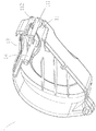
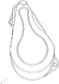
以下、図1乃至19を参照しながら、本実施例をさらに詳しく説明する。本考案の携帯用テープカッター構成は、前端に出口部(11)が設けられ、上面に開口部(12)が設けられ、内側空間(13)に主要組立用部材(14)、収容溝(15)及び位置決め用リブ(16)が設置される後蓋(1)と、前記収容溝(15)内に装設される弾性部材(2)と、プレート(31)の前側面(311)の上端に押し部(32)が設けられ、前記押し部(32)からは押下部(33)が前に向けて延伸され、前記前側面(311)にはバンプ部(34)及びプラットフォーム(35)が設置され、前記プレート(31)には孔部(312)が設けられ、前記プレート(31)の後側面(314)には圧縮用バンプ(36)が設置され、前記プレート(31)の後端には係合リング(37)が設置され、前記係合リング(37)の背面には挟持用スライダー(38)が設置され、前記後蓋(1)に装設され、且つ前記主要組立用部材(14)は前記孔部(312)に貫設され、前記挟持用スライダー(38)は前記位置決め用リブ(16)に着接され、前記圧縮用バンプ(36)が前記収容溝(15)及び前記弾性部材(2)の前端に位置され、前記押し部(32)が前記開口部(12)に位置されるプッシュ用キャリアー(3)と、フレーム部(41)の後端に中空の回転軸(42)が設置され、前記フレーム部(41)の上端に弧状の当接部(43)が設けられ、前記フレーム部(41)の前端にカッター(44)が装設され、前記回転軸(42)により前記後蓋(1)の前記主要組立用部材(14)に装設され、前記バンプ部(34)が前記フレーム部(41)の底面に当接される回転カッターセット(4)と、前記係合リング(37)に結合され、引き出されたテープ先(51)が前記プッシュ用キャリアー(3)の前記プラットフォーム(35)に平らに静置されるテープロール(5)と、前端には出口部(61)が設けられ、上面に開口部(62)が設けられ、前記後蓋(1)に固定されるように結合され、完全な携帯用テープカッター(A)が形成される前蓋(6)とを備える。 Hereinafter, this embodiment will be described in more detail with reference to FIGS. In the portable tape cutter configuration of the present invention, an outlet (11) is provided at the front end, an opening (12) is provided on the upper surface, a main assembly member (14) and a receiving groove (15) are provided in the inner space (13). ) And the rear lid (1) on which the positioning rib (16) is installed, the elastic member (2) installed in the receiving groove (15), and the upper end of the front side surface (311) of the plate (31) The pressing portion (32) is provided with a pressing portion (33) extending forward from the pressing portion (32), and a bump portion (34) and a platform (35) are provided on the front side surface (311). The plate (31) is provided with a hole (312), the plate (31) is provided with a compression bump (36) on the rear surface (314), and the plate (31) has a rear end. Is provided with an engagement ring (37), and the engagement ring ( 7) is provided with a holding slider (38) on the back surface thereof, mounted on the rear lid (1), and the main assembly member (14) is provided through the hole (312) to hold the holding The slider (38) is attached to the positioning rib (16), the compression bump (36) is positioned at the front end of the receiving groove (15) and the elastic member (2), and the pushing portion (32). ) Is a push carrier (3) positioned in the opening (12), a hollow rotating shaft (42) is installed at the rear end of the frame (41), and an arc shape is formed at the upper end of the frame (41). Is provided with a cutter (44) at the front end of the frame portion (41), and the main assembly member (14) of the rear lid (1) by the rotating shaft (42). ), And the bump part (34) is connected to the frame part ( 1) a rotary cutter set (4) abutted against the bottom surface, and a tape tip (51) pulled out and coupled to the engagement ring (37), and the platform (35) of the push carrier (3) The tape roll (5) is placed flat on the front, and the outlet (61) is provided at the front end, the opening (62) is provided on the upper surface, and is fixed to the rear lid (1). And a front lid (6) on which a complete portable tape cutter (A) is formed.
前述の構造により、使用者は片手で本考案を握り持ち、前記出口部(11)(61)を下に向けて前記テープ先(51)を物品の表面に貼り付ける。続いて、本考案を後に向けて引くとテープの貼付部分が伸び、使用者が貼り付ける範囲に達した後、前記プッシュ用キャリアー(3)を押すことにより前記回転カッターセット(4)が連動されてテープが裁断され、片手でのテープカッターの操作が完遂される。使用者が本考案を携帯可能になるのみならず、片手でテープを引き出して切り取る作業を行えるようになり、素早く簡単に使用可能にするという要求を満たす。 With the above-described structure, the user holds the present invention with one hand and attaches the tape tip (51) to the surface of the article with the outlets (11) and (61) facing down. Subsequently, when the present invention is pulled backward, the tape affixed portion is extended, and after reaching the range where the user can affix, the rotary cutter set (4) is interlocked by pressing the push carrier (3). The tape is cut and the operation of the tape cutter with one hand is completed. The user can not only carry the present invention but also pull out the tape with one hand and cut it out to meet the demand for quick and easy use.
なお、前記後蓋(1)の前記出口部(11)には組立用部材(111)が設置され、抑制用ホイール(7)が装設され、前記前蓋(6)の前記出口部(61)には組立用凸部(611)が設置され、前記組立用部材(111)及び前記組立用凸部(611)が結合されることで完全な組立用部材となる。前記テープ先(51)が物品の表面に貼り付けられ、且つ後に向けて引かれると、前記抑制用ホイール(7)がテープに当接されると共に圧迫させ、前記テープが物品の表面に貼付され、貼付及び貼着効果を達成させる。 An assembly member (111) is installed at the outlet (11) of the rear lid (1), a restraining wheel (7) is installed, and the outlet (61) of the front lid (6) is installed. ) Is provided with an assembly projection (611), and the assembly member (111) and the assembly projection (611) are combined to form a complete assembly member. When the tape tip (51) is affixed to the surface of the article and pulled backward, the restraining wheel (7) is brought into contact with and pressed against the tape, and the tape is affixed to the surface of the article. Achieving a sticking and sticking effect
前記前側面(311)には結合用部材(313)が設置され、前記結合用部材(313)には補助ロール(8)が装設され、前記補助ロール(8)にはリブ(81)が設けられる。前記テープの貼付作業において、前記テープの一部が前記補助ロール(8)の上リブに貼り付けられ、前記テープが本考案の内部で部分的に固定される効果が達成される。 A coupling member (313) is installed on the front side surface (311), an auxiliary roll (8) is installed on the coupling member (313), and a rib (81) is installed on the auxiliary roll (8). Provided. In the tape affixing operation, a part of the tape is affixed to the upper rib of the auxiliary roll (8), and the effect that the tape is partially fixed inside the present invention is achieved.
前記後蓋(1)にはカッター収容溝(17)が設けられ、前記前蓋(6)にはカッター収容溝(63)が設けられ、2つの前記カッター収容溝(17)(63)により完全に連通される溝が形成される。使用者が前記押し部(32)を後に向けて押すと、前記押下部(33)が前記回転カッターセット(4)の前記当接部(43)に当接されると共に圧迫させ、前記回転カッターセット(4)が前記回転軸(42)を中心として回転を行い、前記回転カッターセット(4)が下に向けて前記テープを切断させる。2つの前記カッター収容溝(17)(63)が設置されることにより、前記カッター(44)がより深く切断を行うようになり、前記テープがより効果的に裁断され、裁断された前記テープが物品の表面に貼り付けられる。また、前記プラットフォーム(35)にはリブ(351)が設けられ、前記テープ先(51)が部分的に前記リブ(351)に貼付され、前記フレーム部(41)の底面には当接用バンプ(45)が設けられ、前記フレーム部(41)の底面には抑制用バンプ(46)が設けられる。前記回転カッターセット(4)が回転を行うと、前記当接用バンプ(45)が前記リブ(351)に当接され、前記テープが裁断された後、新たに引き出された前記テープ先(51)が前記リブ(351)に貼り付けられ、新しい前記テープ先(51)が乱雑にならない。前記カッター(44)による切断時に前記抑制用バンプ(46)が前記カッター(44)の一側で新たに引き出された前記テープ先(51)の端部を押さえつけ、微力の引張力で切断が補助される効果が達成される。また、新たに引き出された前記テープ先(51)の端部は前記カッター(44)に貼着されない。
前記後蓋(1)の前記出口部(11)には停止用凸部(112)が設けられ、前記前蓋(6)の前記出口部(61)には停止用凸部(612)が設けられ、2つの前記停止用凸部(112)(612)により前記テープ先(51)の端部が前記抑制用ホイール(7)に連れて上に向けて巻き取られる事象が防止され、前記テープ先(5)が正確な位置に位置される。
The rear cover (1) is provided with a cutter receiving groove (17), the front cover (6) is provided with a cutter receiving groove (63), and is completely formed by two cutter receiving grooves (17) and (63). A groove communicated with is formed. When the user pushes the pushing portion (32) backward, the pushing portion (33) is brought into contact with and pressed against the abutting portion (43) of the rotating cutter set (4). The set (4) rotates around the rotation axis (42), and the rotary cutter set (4) cuts the tape downward. By installing the two cutter receiving grooves (17) and (63), the cutter (44) cuts deeper, the tape is cut more effectively, and the cut tape is Affixed to the surface of the article. The platform (35) is provided with a rib (351), the tape tip (51) is partially attached to the rib (351), and a contact bump is formed on the bottom surface of the frame portion (41). (45) is provided, and a suppression bump (46) is provided on the bottom surface of the frame portion (41). When the rotary cutter set (4) rotates, the abutting bump (45) comes into contact with the rib (351), and after the tape is cut, the newly drawn tape tip (51). ) Is affixed to the rib (351), and the new tape tip (51) does not become messy. When the cutter (44) is cut, the restraining bump (46) presses the end of the tape tip (51) newly drawn out on one side of the cutter (44), and the cutting is aided by a slight tensile force. Effect is achieved. Moreover, the edge part of the said tape tip (51) pulled out newly is not stuck to the said cutter (44).
The exit part (11) of the rear lid (1) is provided with a stop convex part (112), and the exit part (61) of the front cover (6) is provided with a stop convex part (612). The event that the end of the tape tip (51) is wound up with the restraining wheel (7) by the two stop convex portions (112) (612) is prevented, and the tape The tip (5) is positioned at the correct position.
前記主要組立用部材(14)、前記組立用部材(111)及び前記結合用部材(313)は柱頭に係合用凸部が設けられる。前記回転カッターセット(4)、前記抑制用ホイール(7)及び前記輔助ロール(8)がそれぞれ装設される際に前記係合用凸部が前記回転カッターセット(4)の前記回転軸(42)、前記抑制用ホイール(7)及び前記輔助ロール(8)に係合され、固定されるように係合されて脱落しなくなる。 The main assembling member (14), the assembling member (111), and the coupling member (313) are provided with engaging convex portions at the stigma. When the rotary cutter set (4), the restraining wheel (7), and the assisting roll (8) are installed, the engaging convex portion is the rotary shaft (42) of the rotary cutter set (4). , Engaged with the restraining wheel (7) and the assisting roll (8), engaged so as to be fixed, and will not fall off.
前記後蓋(1)には当接用リブ(18)が設けられ、前記プッシュ用キャリアー(3)は前記挟持用スライダー(38)により前記位置決め用リブ(16)に係合される。前記プッシュ用キャリアー(3)の滑動時に前記当接用リブ(18)が前記プッシュ用キャリアー(3)を安定させる。前記前蓋(6)には抑制用リブ(64)が設けられ、前記抑制用リブ(64)は本考案の装設後に前記テープロール(5)及び前記係合リング(37)を抑制させ、前記プッシュ用キャリアー(3)が押される際に安定する効果が達成される。また、前記後蓋(1)にはスライド溝(19)が設けられ、前記前蓋(6)にはスライド溝(65)が設けられ、前記プッシュ用キャリアー(3)の両側にはスライドシャフト(39)が設置される。前記プッシュ用キャリアー(3)の滑動時に、2つの前記スライド溝(19)(65)及び前記スライドシャフト(39)により前記プッシュ用キャリアー(3)の安定効果が達成される。また、前記孔部(312)の底縁にはスライド溝(3121)が設けられ、前記回転軸(42)の底端にはスライド溝バンプ(421)が設けられ、前記スライド溝(3121)及び前記スライド溝バンプ(421)により前記プッシュ用キャリアー(3)の前半段の安定が効果的に補助される。 The rear lid (1) is provided with an abutment rib (18), and the push carrier (3) is engaged with the positioning rib (16) by the clamping slider (38). The abutment rib (18) stabilizes the push carrier (3) when the push carrier (3) slides. The front lid (6) is provided with a restraining rib (64), and the restraining rib (64) restrains the tape roll (5) and the engagement ring (37) after installation of the present invention, A stable effect is achieved when the push carrier (3) is pushed. The rear lid (1) is provided with a slide groove (19), the front lid (6) is provided with a slide groove (65), and slide shafts (3) are provided on both sides of the push carrier (3). 39) is installed. When the push carrier (3) slides, a stability effect of the push carrier (3) is achieved by the two slide grooves (19) (65) and the slide shaft (39). Also, a slide groove (3121) is provided at the bottom edge of the hole (312), and a slide groove bump (421) is provided at the bottom end of the rotating shaft (42), and the slide groove (3121) and The slide groove bump (421) effectively assists the stability of the first half of the push carrier (3).
全体的に、本考案の携帯用テープカッター構成により、従来の技術の欠点が改善され、さらに本考案の特徴も発揮される。使用者が本考案を携帯可能になるのみならず、片手でテープを引き出して切り取る作業を完遂でき、素早く簡単に使用可能にするという要求が達成される。 Overall, the portable tape cutter configuration of the present invention improves the disadvantages of the prior art and further demonstrates the features of the present invention. Not only does the user have the ability to carry the present invention, but the need to be able to complete the task of pulling out and cutting the tape with one hand and making it usable quickly and easily is achieved.
従って、本明細書に開示された実施例は、本考案を限定するものではなく、説明するためのものであり、このような実施例によって本考案の思想と範囲が限定されるものではない。本考案の範囲は実用新案登録請求の範囲により解釈すべきであり、それと同等の範囲内にある全ての技術は、実用新案登録請求に含まれるものと解釈すべきである。 Accordingly, the embodiments disclosed herein are for the purpose of explaining, not limiting the present invention, and the spirit and scope of the present invention are not limited by such embodiments. The scope of the present invention should be construed according to the claims for utility model registration, and all technologies within the equivalent scope should be construed as included in the claims for utility model registration.
(A) 携帯式テープカッター
(a) 部分拡大区
(1) 後蓋
(11) 出口部
(111) 組立用部材
(112) 停止用凸部
(12) 開口部
(13) 内側空間
(14) 主要組立用部材
(15) 収容溝
(16) 位置決め用リブ
(17) カッター収容溝
(18) 当接用リブ
(19) スライド溝
(2) 弾性部材
(3) プッシュ用キャリアー
(31) プレート
(311) 前側面
(312) 孔部
(3121) スライド溝
(313) 結合用部材
(314) 後側面
(32) 押し部
(33) 押下部
(34) バンプ部
(35) プラットフォーム
(351) リブ
(36) 圧縮用バンプ
(37) 係合リング
(38) 挟持用スライダー
(39) スライドシャフト
(4) 回転カッターセット
(41) フレーム部
(42) 回転軸
(421) スライド溝バンプ
(43) 当接部
(44) カッター
(45) 当接用バンプ
(46) 抑制用バンプ
(5) テープロール
(51) テープ先
(52) テープ
(6) 前蓋
(61) 出口部
(611) 組立用凸部
(612) 停止用凸部
(62) 開口部
(63) カッター収容溝
(64) 抑制用リブ
(65) スライド溝
(7) 抑制用ホイール
(8) 補助ロール
(81) リブ
(A) Portable tape cutter (a) Partially enlarged section (1) Rear cover (11) Exit (111) Assembly member (112) Stop projection (12) Opening (13) Inner space (14) Main Assembly member (15) Housing groove (16) Positioning rib (17) Cutter housing groove (18) Abutment rib (19) Slide groove (2) Elastic member (3) Push carrier (31) Plate (311) Front side (312) Hole (3121) Slide groove (313) Connecting member (314) Rear side (32) Push part (33) Press part (34) Bump part (35) Platform (351) Rib (36) Compression Bump (37) Engagement ring (38) Nipping slider (39) Slide shaft (4) Rotating cutter set (41) Frame part (42) Rotating shaft 421) Slide groove bump (43) Contact part (44) Cutter (45) Contact bump (46) Suppression bump (5) Tape roll (51) Tape tip (52) Tape (6) Front cover (61) Exit part (611) Assembly convex part (612) Stop convex part (62) Opening part (63) Cutter receiving groove (64) Suppression rib (65) Slide groove (7) Suppression wheel (8) Auxiliary roll ( 81) Ribs
Claims (10)
前記収容溝内に装設される弾性部材と、
プレートの前側面の上端に押し部が設けられ、前記押し部からは押下部が前に向けて延伸され、前記前側面にはバンプ部及びプラットフォームが設置され、前記プレートには孔部が設けられ、前記プレートの後側面には圧縮用バンプが設置され、前記プレートの後端には係合リングが設置され、前記係合リングの背面には挟持用スライダーが設置され、前記後蓋に装設され、且つ前記主要組立用部材は前記孔部に貫設され、前記挟持用スライダーは前記位置決め用リブに着接され、前記圧縮用バンプが前記収容溝及び前記弾性部材の前端に位置され、前記押し部が前記開口部に位置されるプッシュ用キャリアーと、
フレーム部の後端に中空の回転軸が設置され、前記フレーム部の上端には弧状の当接部が設けられ、前記フレーム部の前端にはカッターが装設され、前記回転軸により前記後蓋の前記主要組立用部材に装設され、前記バンプ部は前記フレーム部の底面に当接される回転カッターセットと、
前記係合リングに結合され、引き出されたテープ先が前記プッシュ用キャリアーの前記プラットフォームに平らに静置されるテープロールと、
前端に出口部が設けられ、上面に開口部が設けられ、前記後蓋に固定されるように結合され、完全な携帯式テープカッター構造が形成される前蓋とを備えることを特徴とする携帯式テープカッター構成。 A rear lid in which an outlet is provided at the front end, an opening is provided in the upper surface, and a main assembly member, a housing groove and a positioning rib are installed in the inner space;
An elastic member installed in the receiving groove;
A pressing part is provided at the upper end of the front side surface of the plate, a pressing part is extended forward from the pressing part, a bump part and a platform are installed on the front side surface, and a hole is provided in the plate. A compression bump is installed on the rear side of the plate, an engagement ring is installed on the rear end of the plate, a clamping slider is installed on the back of the engagement ring, and is mounted on the rear lid. And the main assembly member is penetrated in the hole, the clamping slider is attached to the positioning rib, and the compression bump is positioned at the front end of the receiving groove and the elastic member, A push carrier in which the push portion is positioned in the opening;
A hollow rotating shaft is installed at the rear end of the frame portion, an arc-shaped contact portion is provided at the upper end of the frame portion, a cutter is installed at the front end of the frame portion, and the rear lid is supported by the rotating shaft. A rotary cutter set mounted on the main assembly member, and the bump portion abutting against the bottom surface of the frame portion;
A tape roll coupled to the engagement ring and withdrawn tape tip resting flat on the platform of the push carrier;
A portable body comprising an outlet at a front end, an opening at an upper surface, and a front lid that is coupled to be fixed to the rear lid to form a complete portable tape cutter structure. Type tape cutter configuration.
Priority Applications (1)
| Application Number | Priority Date | Filing Date | Title |
|---|---|---|---|
| JP2018000184U JP3215593U (en) | 2018-01-19 | 2018-01-19 | Portable tape cutter configuration |
Applications Claiming Priority (1)
| Application Number | Priority Date | Filing Date | Title |
|---|---|---|---|
| JP2018000184U JP3215593U (en) | 2018-01-19 | 2018-01-19 | Portable tape cutter configuration |
Publications (1)
| Publication Number | Publication Date |
|---|---|
| JP3215593U true JP3215593U (en) | 2018-03-29 |
Family
ID=61756467
Family Applications (1)
| Application Number | Title | Priority Date | Filing Date |
|---|---|---|---|
| JP2018000184U Active JP3215593U (en) | 2018-01-19 | 2018-01-19 | Portable tape cutter configuration |
Country Status (1)
| Country | Link |
|---|---|
| JP (1) | JP3215593U (en) |
Cited By (1)
| Publication number | Priority date | Publication date | Assignee | Title |
|---|---|---|---|---|
| KR102128309B1 (en) * | 2020-02-14 | 2020-06-30 | 대구보건대학교산학협력단 | cutting unit of kinesiology tape |
-
2018
- 2018-01-19 JP JP2018000184U patent/JP3215593U/en active Active
Cited By (1)
| Publication number | Priority date | Publication date | Assignee | Title |
|---|---|---|---|---|
| KR102128309B1 (en) * | 2020-02-14 | 2020-06-30 | 대구보건대학교산학협력단 | cutting unit of kinesiology tape |
Similar Documents
| Publication | Publication Date | Title |
|---|---|---|
| TWI478856B (en) | Tape cutter | |
| JP3215593U (en) | Portable tape cutter configuration | |
| WO2013163783A1 (en) | Utility knife | |
| CN201002732Y (en) | Box sealing instrument | |
| CN201102645Y (en) | Joint sealing device | |
| KR101651360B1 (en) | Fixing device | |
| CN201250033Y (en) | Adhesive tape cutter | |
| CN213072772U (en) | Sucking disc formula cell phone stand | |
| CN210903178U (en) | Effort-saving anorectal anastomat | |
| CN220483683U (en) | Film pasting external member | |
| CN216938352U (en) | Portable switch cover burring device | |
| CN216945581U (en) | Pure aluminium foil sticky tape pastes and applies device | |
| JPH0638843Y2 (en) | Adhesive tape holder | |
| CN218478345U (en) | Improved adhesive tape cutter | |
| CN216235222U (en) | Double faced adhesive tape pastes device fast | |
| CN212653316U (en) | Positioning jig | |
| TWM563388U (en) | Safe folding structure of scooter | |
| TWM380877U (en) | Tile cutter | |
| CN212024385U (en) | Rolling device with wire guide function | |
| JP2005131360A5 (en) | ||
| US6666898B2 (en) | Adhesive-tape cutting device of an adhesive-tape holder | |
| JP3015914U (en) | Adhesive tape cutter | |
| KR100750296B1 (en) | Tape cutting | |
| JP4454486B2 (en) | Handy tape cutter | |
| TWI695806B (en) | Improved structure of hand-held glue table |
Legal Events
| Date | Code | Title | Description |
|---|---|---|---|
| R150 | Certificate of patent or registration of utility model |
Ref document number: 3215593 Country of ref document: JP Free format text: JAPANESE INTERMEDIATE CODE: R150 |
|
| R250 | Receipt of annual fees |
Free format text: JAPANESE INTERMEDIATE CODE: R250 |