JP3211331U - Cutting equipment - Google Patents
Cutting equipment Download PDFInfo
- Publication number
- JP3211331U JP3211331U JP2017001808U JP2017001808U JP3211331U JP 3211331 U JP3211331 U JP 3211331U JP 2017001808 U JP2017001808 U JP 2017001808U JP 2017001808 U JP2017001808 U JP 2017001808U JP 3211331 U JP3211331 U JP 3211331U
- Authority
- JP
- Japan
- Prior art keywords
- housing
- frame
- peripheral wall
- power supply
- receiving port
- Prior art date
- Legal status (The legal status is an assumption and is not a legal conclusion. Google has not performed a legal analysis and makes no representation as to the accuracy of the status listed.)
- Expired - Fee Related
Links
Images


Classifications
-
- B—PERFORMING OPERATIONS; TRANSPORTING
- B43—WRITING OR DRAWING IMPLEMENTS; BUREAU ACCESSORIES
- B43L—ARTICLES FOR WRITING OR DRAWING UPON; WRITING OR DRAWING AIDS; ACCESSORIES FOR WRITING OR DRAWING
- B43L23/00—Sharpeners for pencils or leads
- B43L23/008—Sharpeners for pencils or leads with rotating cutting bodies
-
- B—PERFORMING OPERATIONS; TRANSPORTING
- B43—WRITING OR DRAWING IMPLEMENTS; BUREAU ACCESSORIES
- B43L—ARTICLES FOR WRITING OR DRAWING UPON; WRITING OR DRAWING AIDS; ACCESSORIES FOR WRITING OR DRAWING
- B43L23/00—Sharpeners for pencils or leads
- B43L23/02—Sharpeners for pencils or leads with gearing
-
- B—PERFORMING OPERATIONS; TRANSPORTING
- B43—WRITING OR DRAWING IMPLEMENTS; BUREAU ACCESSORIES
- B43L—ARTICLES FOR WRITING OR DRAWING UPON; WRITING OR DRAWING AIDS; ACCESSORIES FOR WRITING OR DRAWING
- B43L23/00—Sharpeners for pencils or leads
- B43L23/08—Sharpeners for pencils or leads in which the pencils or leads are sharpened mainly by rotational movement against cutting blades
Landscapes
- Drawing Aids And Blackboards (AREA)
- Dry Shavers And Clippers (AREA)
Abstract
【課題】削り滓の収集機能を確保できる切削装置を提供する。【解決手段】内部空間20を囲む内周面22を有するハウジング2と、内部空間20内に収容されるようにハウジング2に取り付けられるフレーム1と、フレーム1に取り付けられると共に、鉛筆を削るよう切削できるカッター手段500と、を備え、フレーム1は、内周面22に臨む周壁125と、ハウジング2の内周面22に当接するように周壁125から突起し、フレーム1をハウジング2に位置付けする少なくとも1つの当接突起140と、を有している。【選択図】図2The present invention provides a cutting device capable of securing a shaving rod collecting function. A housing having an inner peripheral surface that surrounds an internal space, a frame that is attached to the housing so as to be accommodated in the internal space, and a blade that is attached to the frame and that is cut to sharpen a pencil. The frame 1 has at least a peripheral wall 125 facing the inner peripheral surface 22, a projection protruding from the peripheral wall 125 so as to contact the inner peripheral surface 22 of the housing 2, and positioning the frame 1 at the housing 2. One abutting protrusion 140. [Selection] Figure 2
Description
本考案は切削装置に関し、特に鉛筆を削るための切削装置に関する。 The present invention relates to a cutting device, and more particularly to a cutting device for sharpening a pencil.
鉛筆の軸を削って芯を露出させる通称鉛筆削りの従来の切削装置は、例えば鉛筆が挿入できる削り穴を有するハウジングと、該ハウジングの内部に設置されて鉛筆の軸を削るカッターと、該ハウジングに取り外し可能に取り付けられると共に、前記カッターの下側に配置される箱状のケースと、を備えているものである。なお、カッターとしては、通常らせん状の刃などが使用される。 A conventional cutting device of a so-called pencil sharpener that sharpens a pencil axis to expose a core includes, for example, a housing having a sharpened hole into which a pencil can be inserted, a cutter that is installed inside the housing and sharpens the pencil axis, and the housing And a box-shaped case disposed on the lower side of the cutter. As the cutter, a spiral blade or the like is usually used.
上記の構造によれば、該従来の切削装置に対して、鉛筆の一端部を前記ハウジングの前記削り穴に挿入してから、前記カッターで該端部を削りながら、該鉛筆から削られた削り滓を前記ケースに落として収集し、該鉛筆を削るための作業を終えたら、前記ケースを前記ハウジングから引き出して取り外して、該前記ケースに収集した前記削り滓をまとめて捨てることができる。 According to the above structure, with respect to the conventional cutting device, the one end of the pencil is inserted into the shaving hole of the housing, and then the shaving scraped from the pencil while the end is shaved with the cutter. When the scissors are dropped and collected in the case and the work for shaving the pencil is completed, the case can be pulled out and removed from the housing, and the shavings collected in the case can be discarded together.
しかしながら、該従来の切削装置は、前記カッターが鉛筆を削る作業において生じる振動により、前記ケースが前記ハウジングから抜けて削り滓をこぼしてしまう恐れがある。 However, in the conventional cutting apparatus, there is a risk that the case may come off from the housing and spill the shavings due to the vibration generated when the cutter sharpens the pencil.
上記問題点に鑑みて、本考案は、削り滓の収集機能を確保できる切削装置の提供を目的とする。 In view of the above problems, an object of the present invention is to provide a cutting apparatus that can secure a shaving collection function.
上記目的を達成すべく、本考案の切削装置は、内部空間を囲む内周面を有するハウジングと、前記内部空間内に収容されるように前記ハウジングに取り付けられるフレームと、前記フレームに取り付けられると共に、鉛筆の軸を切削できるカッターと、を備え、前記フレームは、前記内周面に臨む周壁と、前記ハウジングの前記内周面に当接するように前記周壁から突起し、前記フレームを前記ハウジングに位置付けする少なくとも1つの当接突起と、を有している。 In order to achieve the above object, a cutting device of the present invention includes a housing having an inner peripheral surface surrounding an internal space, a frame attached to the housing so as to be accommodated in the internal space, and attached to the frame. A cutter capable of cutting a pencil shaft, and the frame protrudes from the peripheral wall so as to abut on the inner peripheral surface of the housing and the peripheral wall facing the inner peripheral surface, and the frame is attached to the housing. And at least one abutting protrusion for positioning.
上記構成によれば、本考案の切削装置は、前記カッターを付けて前記ハウジングの前記内部空間に収容される前記フレームと、前記フレームを前記ハウジングに位置付けして保持する前記当接突起と、を備えているため、前記フレームが前記ハウジングに固く係止されているので、前記内部空間において安定して鉛筆の切削作業を行うことができると同時に、前記フレームが前記ハウジングから取り出さない限り、削り滓が該ハウジングからこぼれ出されることはない。 According to the above configuration, the cutting device of the present invention includes the frame that is attached to the inner space of the housing with the cutter, and the contact protrusion that positions and holds the frame on the housing. Since the frame is firmly fixed to the housing, the pencil can be stably cut in the internal space. At the same time, unless the frame is removed from the housing, Will not spill out of the housing.
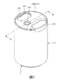
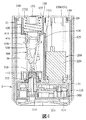
以下、図1〜図5を参照しながら、本考案の切削装置を例示する実施形態について詳しく説明する。図1は本考案の実施形態が示される斜視図である。図2は本考案の実施形態における構造が示される分解斜視図である。図3は本考案の実施形態におけるフレームが示される斜視図である。図4は本考案の実施形態における内部構造が示される断面図である。そして、図5は本考案の実施形態におけるカッターに対する保持が解除されている状態が示される断面図である。 Hereinafter, embodiments illustrating the cutting device of the present invention will be described in detail with reference to FIGS. 1 to 5. FIG. 1 is a perspective view showing an embodiment of the present invention. FIG. 2 is an exploded perspective view showing the structure of the embodiment of the present invention. FIG. 3 is a perspective view showing a frame in the embodiment of the present invention. FIG. 4 is a cross-sectional view showing an internal structure in the embodiment of the present invention. FIG. 5 is a cross-sectional view showing a state in which the holding of the cutter in the embodiment of the present invention is released.
本考案の切削装置は、鉛筆の軸を削って芯を露出させるよう切削するものであり、図2に示すハウジング2と、ハウジング2の内部に取り外し可能に取り付けられるフレーム1と、フレーム1に回転可能且つ取り外し可能に取り付けられると共に、鉛筆の軸を切削できるカッター500と、フレーム1に設置されている圧縮コイルばね420と、カッター500を回転駆動する駆動手段200と、駆動手段200の駆動力をカッター手段500に伝える伝動手段300と、フレーム1に取り付けられる蓋手段150と、を備えている。
The cutting device of the present invention is for cutting a pencil shaft so as to expose a core. The
図1に示されるように、本実施形態におけるハウジング2は、両端開口の円筒状に形成され、フレーム1を収容する内部空間20を囲む内周面22を有し、前記両端における一端部(図中の上端)の開口が内部空間20と連通する受入口24である。更に、受入口24の周縁には嵌合溝23が凹設されている。なお、本実施形態はこの構成に限定されることなく、ハウジング2としては、フレーム1を収容できればよく、必ずしも端部に受入口24が形成される構成である必要はない。
As shown in FIG. 1, the
図2に示されるようにフレーム1は、ハウジング2の内部空間20に合わせた略円柱状に形成され、そして内部空間20内に収容されるようハウジング2に取り外し可能に取り付けられている。図3に示されるようにフレーム1は、ハウジング2及びフレーム1の中心軸線を中心とする円弧板状に形成された周壁125と、周壁125の一端部に接続されているベース部110と、周壁125の他端部に接続されているトップ部130と、周壁125及びベース部110及びトップ部130とに接続され、フレーム1のベース部110とトップ部130との間の空間を仕切る仕切り板126と、周壁125からハウジング2の内周面22に当接できるように突起する複数の当接突起140と、を有している。
As shown in FIG. 2, the
図4に示されるように、ベース部110にはトップ部130に向かって開口する下ソケット112が形成されており、トップ部130には、両端に前記下ソケット112に臨む下開口1331と、ハウジング2の受入口24に臨む上開口1332と、がそれぞれ開けられている上ソケット133が形成されており、下ソケット112と上ソケット133との間に、カッター手段500が回転可能に保持されている。
As shown in FIG. 4, the
駆動手段200は、カッター手段500を回転駆動するモーター220と、モーター220に給電する電源ユニット210と、電源ユニット210のモーター220に対する給電のオン/オフを制御できるスイッチ230と、を有している。
The
図3及び図4に示されるように、仕切り板126は、フレーム1のベース部110とトップ部130との間の空間を、カッター手段500が回転可能に保持されている収集室36(図4)と、駆動手段200のモーター220、電源ユニット210、及びスイッチ230を収容する収容室32とに仕切る。
As shown in FIGS. 3 and 4, the
また、ベース部110は伝動室31を囲むように中空に形成され、伝動室31内に収容室32にある回転駆動するモーター220による駆動力を収集室36にあるカッター手段500に伝送する伝動手段300が配置されている。
Further, the
スイッチ230は収容室32から周壁120の外側に突出してハウジング2の内周面22に当接できるように構成されており、図1と図4に示されるように、フレーム1がハウジング2に取り付けられている際にレバー231(図3)は、ハウジング2の内周面22に当接して該内周面22により周壁125側に押付けられ、図3と図5に示されるように、フレーム1がハウジング2から取り外される際にスイッチ230は、収容室32から周壁120の外側に突出するようになっていると共に、ハウジング2の内周面22に当接して該内周面22により周壁125側に押付けられると、電源ユニット210からのモーター220に対する給電を切断せずに電気を通すオン状態に設定され、そして収容室32から周壁120の外側に突出すると、電源ユニット210からのモーター220に対する給電を切断するオフ状態に設定されている。この構成により、フレーム1がハウジング2から取り外されない限り電源ユニット210はモーター220に対して給電し続け、そしてフレーム1がハウジング2から取り外されると電源ユニット210による給電は停止される。即ち、フレーム1がハウジング2から取り外された状態における安全性と、オン/オフの切替操作が不要な利便性を兼ね備えている。
The
なお、スイッチ230としては、ハウジング2の内周面22により動かされるタイプのスイッチの他、光や磁場の変化を感知するタイプのスイッチなどに適宜変更するのも可能であり、本実施形態に限定されることはない。
The
伝動手段300は、ベース部110の内部に配置されてモーター220により回転駆動される複数のギア311と、ベース部110から下ソケット112に突出し、各ギア311及びモーター220により回転駆動されると共に、カッター手段500を回転駆動する出力軸312と、を有している。
The transmission means 300 is disposed inside the
トップ部130は、ハウジング2の受入口24側を覆うように配置され、収容室32と連通する電池開口35(図2を参照)が開けられている。
The
各当接突起140は、摩擦力が高いゴムなどの材料により作成されたものであり、そして周壁125の凸面側においてハウジング2の受入口24に隣接する端部から内周面22に当接するよう突出して、フレーム1をハウジング2に位置付けするができる。なお、本実施形態に制限されず、当接突起140の数量は少なくとも1つがあれば良く、そして、フレーム1をハウジング2に位置付けできるように周壁125からの突起位置も適宜変更可能である。
Each
図2に示すように、トップ部130に形成された上ソケット133内に、該上ソケット133が有する上開口1332と下開口1331との間に移動可能な摺動枠410が配置されている。
As shown in FIG. 2, a
図3及び図4に示すように、カッター手段500は、摺動枠410に取付けられていると共に、上ソケット133から下ソケット112側へ突出する上プラグ520と、伝動手段300の出力軸312と共に回転できるように出力軸312に取付けられている下プラグ510と、上プラグ520と下プラグ510との間に取り外し可能なカッター本体530とを有している。
As shown in FIGS. 3 and 4, the
蓋手段150は、ハウジング2の受入口24を封止できるように構成されており、メインカバー151と、トップ部130の電池開口35に対応し、メインカバー151に取り外し可能に取り付けられている電池カバー155とを有している。
The lid means 150 is configured to seal the
更に、蓋手段150のメインカバー151とトップ部130との間に、一端部が摺動枠410を下ソケット112へ当接するように設置されている圧縮コイルばね420が取り付けられている。なお、摺動枠410には、上ソケット133と連通するように、上開口1332側から下開口側1331へ貫通する鉛筆通過路411が開けられている。
Further, a
メインカバー151は、トップ部130にある上ソケット133の上開口1332を覆うと共に、保持手段400の圧縮コイルばね420にある前記一端部と反対側の他端部に当接されるように、トップ部130に取付けられている。また、メインカバー151は、ハウジング2の嵌合溝23と嵌合できるように突起するブロック152を有し、そして上ソケット133と連通するようその上開口1332に向かって開口する鉛筆挿入口153と、トップ部130の電池開口35に臨む電池取替え口154(図2を参照)とが設けられている。
The
一方、図1と図2に示されるように電池カバー155は、金属により形成され、そして、トップ部130(図2)にある電池開口35を覆って収容室32に設置さている各電池211を電気的に直列接続すると共に、メインカバー151の電池取替え口154を取り外し可能に封止するよう取付けられている。
On the other hand, as shown in FIGS. 1 and 2, the
すなわち、図3に示すように2つの電池211は、一方の電池211のプラス側が上になるように配置され(図3において右側)、他方の電池211のマイナス側が上になるように配置され(図3において左側)、金属により形成された電池カバー155によって、これら2つの電池のプラス側端子とマイナス側端子を直列に接続する。
That is, as shown in FIG. 3, the two
ちなみに、本実施形態におけるメインカバー151はプラスチックなどにより形成されており、一方、各電池211と電気的に接続するための金属からなる電池カバー155は、メインカバー151より厚みが薄い薄板に作製されて、メインカバー151とトップ部130との間に挟まれていると共に、電池取替え口154から露出している。この設計によれば、メインカバー151と電池カバー155の両方の材料コストの節約になる上、電池カバー155の金属による装飾効果をもたらすこともできる。
Incidentally, the
上記の構造によれば、本考案の切削装置は、図1と図4に示されるように、フレーム1がハウジング2に取り付けられると共に、駆動手段200(図4)のスイッチ230がオン状態となってモーター220を作動してから、伝動手段300を介して保持されているカッター手段500を回転させることができる。
According to the above structure, in the cutting apparatus of the present invention, as shown in FIGS. 1 and 4, the
次にこのオン状態で、鉛筆(図示せず)の先端部を蓋手段150の鉛筆挿入口153から、フレーム1の上ソケット133と上ソケット133の内部にある摺動枠410の鉛筆通過路411を経由して、回転中のカッター手段500にある削り穴530に差し込むと、該鉛筆の軸はカッター手段500に削られる。そして、カッター手段500が該鉛筆の軸から切り落とした削り滓は、ハウジング2の内部空間20において内周面22とフレーム1により囲んだ収集室36に収集される。
Next, in this ON state, the pencil (not shown) tip is moved from the
ここでは、フレーム1にある各当接突起140とハウジング2の内周面22との当接による摩擦力、そして蓋手段150のブロック152とハウジング2の嵌合溝23との嵌合によって、フレーム1とハウジング2とは、互いに回転不能に固く係止されているので、モーター220の作動やカッター手段500が鉛筆の軸を切削する際において生じる振動により、互いの接合構造が緩まることにより両者が分解されて削り滓がこぼれてしまうことがないよう、有効に収集室36の機能を確保できる。
Here, the frictional force caused by the contact between each
そして、前記鉛筆の切削作業が終えたら、該鉛筆を鉛筆挿入口153から抜き出し、フレーム1をハウジング2の受入口24から押し出して、内部空間20にある削り滓をまとめて捨てることができる。
When the pencil cutting operation is completed, the pencil can be extracted from the
また、取替えや別の場所に収納するなどの理由でカッター手段500をフレーム1から取り外す場合には、図5に示されるように、フレーム1をハウジング2から取り外した上、駆動手段200及びカッター手段500が停止している状態においてカッター手段500を、摺動枠410ごと上ソケット133内へ移動して、その下プラグ510を下ソケット112及び回転座320から抜き出してから、摺動枠410から取り外すことで、上ソケット133と下ソケット112の両方からの保持を解除できる。
Further, when the cutter means 500 is removed from the
ちなみに、本考案の切削装置は、駆動手段200と伝動手段300を取り除き、そしてカッター手段500が上ソケット133と下ソケット112で回転不能に保持されるよう適宜変更することも可能である。そうすると、カッター手段500の削り穴530に挿入している鉛筆の方を手動で回転させて切削を行うと良い。
Incidentally, the cutting device of the present invention can be changed as appropriate so that the driving means 200 and the transmission means 300 are removed and the cutter means 500 is held non-rotatably by the
上記の実施形態によれば、本考案の切削装置は、カッター手段500を付けてハウジング2の内部空間20に収容されるフレーム1と、フレーム1をハウジング2に位置付けして保持する当接突起140とを備え、更にハウジング2の嵌合溝23とを嵌合できるブロック152を有する蓋手段150も備えているため、フレーム1がハウジング2に固く係止されているので、内部空間20において安定して鉛筆の切削作業を行うことができると同時に、該鉛筆からの削り滓がハウジング2からこぼれ出ないように収集機能を確保することができる。
According to the above-described embodiment, the cutting device of the present invention is provided with the
以上、本考案の好ましい実施形態を説明したが、本考案はこれに限定されるものではなく、その要旨を逸脱しない範囲で種々変更可能である。 As mentioned above, although preferred embodiment of this invention was described, this invention is not limited to this, A various change is possible in the range which does not deviate from the summary.
上記構成によれば、本考案の切削装置は、前記カッターを付けて前記ハウジングの前記内部空間に収容される前記フレームと、前記フレームを前記ハウジングに位置付けして保持する前記当接突起と、を備えているため、前記フレームが前記ハウジングに固く係止されているので、前記内部空間において安定に鉛筆の切削作業を行う同時に、前記フレームが前記ハウジングから取り出さない限り、削り滓が該ハウジングからこぼれ出されることはない優れた切削装置を提供することができる。 According to the above configuration, the cutting device of the present invention includes the frame that is attached to the inner space of the housing with the cutter, and the contact protrusion that positions and holds the frame on the housing. Since the frame is firmly locked to the housing, a pencil cutting operation is stably performed in the internal space. At the same time, unless the frame is taken out from the housing, a shaving spill is spilled from the housing. It is possible to provide an excellent cutting device that is not released.
1 フレーム
110 ベース部
112 下ソケット
125 周壁
126 仕切り板
130 トップ部
133 上ソケット
1331 下開口
1332 上開口
140 当接突起
150 蓋手段
151 メインカバー
152 ブロック
153 鉛筆挿入口
154 電池取替え口
155 電池カバー
2 ハウジング
20 内部空間
22 内周面
23 嵌合溝
24 受入口
200 駆動手段
220 モーター
210 電源ユニット
211 電池
230 スイッチ
231 レバー
31 伝動室
32 収容室
35 電池開口
36 収集室
300 伝動手段
311 ギア
312 出力軸
410 摺動枠
411 鉛筆通過路
420 圧縮コイルばね
500 カッター手段
510 下プラグ
520 上プラグ
530 カッター本体
DESCRIPTION OF
Claims (10)
前記内部空間内に収容されるように前記ハウジングに取り付けられるフレームと、
前記フレームに取り付けられると共に、鉛筆の軸を切削できるカッター手段と、を備え、
前記フレームは、
前記内周面に臨む周壁と、
前記ハウジングの前記内周面に当接するように前記周壁から突起し、前記フレームを前記ハウジングに位置付けする少なくとも1つの当接突起と、を有していることを特徴とする切削装置。 A housing having an inner peripheral surface surrounding the internal space;
A frame attached to the housing so as to be received in the internal space;
A cutter means attached to the frame and capable of cutting a pencil axis;
The frame is
A peripheral wall facing the inner peripheral surface;
A cutting apparatus comprising: at least one abutting projection that projects from the peripheral wall so as to abut on the inner peripheral surface of the housing and positions the frame on the housing.
前記フレームは前記受入口を経由して前記内部空間内に収容されており、
前記当接突起は、前記フレームの前記周壁の前記受入口に隣接する端部に、複数取付けられていることを特徴とする請求項1に記載の切削装置。 A receiving port communicating with the internal space is formed at one end of the housing,
The frame is accommodated in the internal space via the receiving port,
The cutting device according to claim 1, wherein a plurality of the contact protrusions are attached to an end portion of the peripheral wall of the frame adjacent to the receiving port.
また、前記フレームは、
前記周壁の前記内部空間内に深く挿し込まれた端部に接続されたベース部と、
前記周壁の前記受入口側にある端部に接続されたトップ部と、
前記周壁に接続されていると共に、両端はそれぞれ前記ベース部と前記トップ部とに接続されている仕切り板と、を更に有し、
前記ベース部と、前記トップ部と、前記仕切り板と、前記周壁とにより、収容室が画成され、
該収容室内に、
前記カッター手段を回転駆動するモーターと、
前記モーターに給電する電源ユニットと、
前記電源ユニットの前記モーターに対する給電のオンとオフを制御できるスイッチと、を有する駆動手段が配置されていることを特徴とする請求項2に記載の切削装置。 The cutter means is rotatably held by the frame,
The frame is
A base portion connected to an end portion deeply inserted into the internal space of the peripheral wall;
A top portion connected to an end of the peripheral wall on the receiving side;
A partition plate connected to the peripheral wall and having both ends respectively connected to the base portion and the top portion;
A storage chamber is defined by the base portion, the top portion, the partition plate, and the peripheral wall,
In the containment chamber,
A motor that rotationally drives the cutter means;
A power supply unit for supplying power to the motor;
The cutting apparatus according to claim 2, further comprising: a driving unit having a switch capable of controlling on / off of power supply to the motor of the power supply unit.
前記駆動手段が有する前記スイッチは、前記周壁から突起して前記ハウジングの前記内周面に当接できるように付勢されるレバーを有しており、
また、前記スイッチは、
前記フレームが前記ハウジングから取り外される際、前記レバーは付勢されて前記周壁から突起すると共に、前記電源ユニットからの前記モーターに対する給電を切断するオフ位置にあり、
そして前記フレームが前記内部空間内に収容される際、前記レバーは前記ハウジングの前記内周面に当接すると共に、前記内周面により前記周壁側に押付けられて前記電源ユニットからの前記モーターに対する給電を切断しないオン位置にあるように配置構成されていることを特徴とする請求項3に記載の切削装置。 The frame is configured to be removable from the housing via the receiving port,
The switch of the driving means has a lever that protrudes from the peripheral wall and is urged so as to come into contact with the inner peripheral surface of the housing.
In addition, the switch
When the frame is removed from the housing, the lever is biased to protrude from the peripheral wall, and is in an off position to cut off the power supply to the motor from the power supply unit,
When the frame is accommodated in the internal space, the lever contacts the inner peripheral surface of the housing and is pressed against the peripheral wall by the inner peripheral surface to supply power to the motor from the power supply unit. The cutting apparatus according to claim 3, wherein the cutting apparatus is arranged so as to be in an on position where the cutting is not performed.
前記フレームには、前記嵌合溝と嵌合できるように突起するブロックが形成されていることを特徴とする請求項4に記載の切削装置。 A fitting groove is recessed in the periphery of the receiving port of the housing,
The cutting device according to claim 4, wherein the frame is formed with a block that protrudes so as to be fitted into the fitting groove.
前記トップ部には、両端に前記下ソケットに臨む開口と、前記ハウジングの前記受入口に臨む開口と、がそれぞれ開けられている上ソケットが形成されており、
前記下ソケットと前記上ソケットとの間に、前記カッター手段が回転可能に保持されていることを特徴とする請求項5に記載の切削装置。 The base part is formed with a lower socket that opens toward the top part,
The top portion is formed with an upper socket in which an opening facing the lower socket and an opening facing the receiving port of the housing are opened at both ends,
6. The cutting apparatus according to claim 5, wherein the cutter means is rotatably held between the lower socket and the upper socket.
該切削装置は更に、
前記ハウジングの前記受入口を封止する蓋手段と、
両端がそれぞれ前記蓋手段と前記摺動枠に当接している圧縮コイルばねと、を備えていることを特徴とする請求項6に記載の切削装置。 In the upper socket formed in the top portion, a sliding frame is disposed that is movable between two openings of the upper socket and to which one end of the cutter means is attached.
The cutting device further includes:
Lid means for sealing the receiving port of the housing;
7. The cutting apparatus according to claim 6, further comprising a compression coil spring having both ends abutting against the lid means and the sliding frame.
前記蓋手段には、前記トップ部の前記電池開口に臨む電池取替え口が形成されている上、該電池取替え口を取り外し可能に封止する電池カバーが取付けられていることを特徴とする請求項9に記載の切削装置。 The top portion is formed with a battery opening through which a battery included in the power supply unit of the driving means accommodated in the accommodation chamber is exposed,
The battery cover for attaching the battery replacement opening to the battery opening is formed on the lid means so as to face the battery opening of the top portion, and the battery replacement opening is removably sealed. 9. The cutting device according to 9.
Applications Claiming Priority (2)
| Application Number | Priority Date | Filing Date | Title |
|---|---|---|---|
| CN201620384634.6 | 2016-04-29 | ||
| CN201620384634.6U CN206367326U (en) | 2016-04-29 | 2016-04-29 | Pencil sharpener |
Publications (1)
| Publication Number | Publication Date |
|---|---|
| JP3211331U true JP3211331U (en) | 2017-07-06 |
Family
ID=59272827
Family Applications (1)
| Application Number | Title | Priority Date | Filing Date |
|---|---|---|---|
| JP2017001808U Expired - Fee Related JP3211331U (en) | 2016-04-29 | 2017-04-21 | Cutting equipment |
Country Status (5)
| Country | Link |
|---|---|
| US (1) | US20170313122A1 (en) |
| JP (1) | JP3211331U (en) |
| CN (1) | CN206367326U (en) |
| DE (1) | DE202017102473U1 (en) |
| TW (1) | TWM546917U (en) |
Families Citing this family (3)
| Publication number | Priority date | Publication date | Assignee | Title |
|---|---|---|---|---|
| USD859521S1 (en) * | 2017-08-02 | 2019-09-10 | Sunwood Holding Group Co., Ltd. | Pencil sharpener |
| USD888152S1 (en) * | 2018-03-16 | 2020-06-23 | Qingmei LI | Pencil sharpener |
| CN113844201B (en) * | 2021-10-19 | 2022-11-22 | 义乌市鼎邦文体用品有限公司 | Electric pencil sharpener with thickness adjusting function |
Family Cites Families (18)
| Publication number | Priority date | Publication date | Assignee | Title |
|---|---|---|---|---|
| US836712A (en) * | 1905-04-04 | 1906-11-27 | Delbert D Rush | Pencil-sharpener. |
| US1038112A (en) * | 1911-10-25 | 1912-09-10 | Frederick A Fricker | Pencil-sharpener. |
| US1941215A (en) * | 1929-10-12 | 1933-12-26 | Liggio Leoluca | Electric pencil sharpener |
| US2189476A (en) * | 1938-10-03 | 1940-02-06 | Siggelko Edgar Stanley | Pencil sharpening machine |
| US2900958A (en) * | 1958-08-22 | 1959-08-25 | Gerald A Johnson | Electric pencil sharpener |
| US4601316A (en) * | 1985-09-30 | 1986-07-22 | Ketcham & Mcdougall, Inc. | Electric pencil sharpener |
| US5875555A (en) * | 1996-02-09 | 1999-03-02 | The Little Tikes Company | Crayon sharpener assembly |
| US6553882B1 (en) * | 2000-04-05 | 2003-04-29 | Hunt Holdings, Inc. | Pencil sharpener with integral receptacle |
| US6845795B2 (en) * | 2002-07-25 | 2005-01-25 | Innodesk Business Tools Inv. | Portable handheld sharpener with loop attachment |
| US7934319B2 (en) * | 2002-10-28 | 2011-05-03 | Acme United Corporation | Pencil-sharpening device |
| JP2006110805A (en) * | 2004-10-13 | 2006-04-27 | Ktf:Kk | Pencil sharpening machine |
| US7654179B2 (en) * | 2006-07-26 | 2010-02-02 | Elmer's Products, Inc. | Crayon sharpener |
| US7699082B2 (en) * | 2006-12-18 | 2010-04-20 | Yurisheng Electronic (Shenzhen) Co., Ltd | Electric multi-pencil sharpener |
| US20110186178A1 (en) * | 2007-12-21 | 2011-08-04 | Shen-Hsiung Chang | Safety device for an electric pencil sharpener |
| TW201026522A (en) * | 2009-01-13 | 2010-07-16 | Sdi Corp | Power pencil sharper capable of replacing knives |
| TWI503238B (en) * | 2012-01-20 | 2015-10-11 | Sdi Corp | Replaceable tool with electric pencil sharpener |
| US20160263934A1 (en) * | 2015-03-13 | 2016-09-15 | Acme United Corporation | Pencil Sharpener with Notification Light |
| US9889651B2 (en) * | 2015-03-30 | 2018-02-13 | Funai Electric Co., Ltd. | Fluid ejection device for depositing a discrete quantity of fluid onto a surface |
-
2016
- 2016-04-29 CN CN201620384634.6U patent/CN206367326U/en not_active Expired - Fee Related
-
2017
- 2017-03-14 TW TW106203539U patent/TWM546917U/en not_active IP Right Cessation
- 2017-04-21 JP JP2017001808U patent/JP3211331U/en not_active Expired - Fee Related
- 2017-04-25 US US15/496,012 patent/US20170313122A1/en not_active Abandoned
- 2017-04-26 DE DE202017102473.3U patent/DE202017102473U1/en not_active Expired - Lifetime
Also Published As
| Publication number | Publication date |
|---|---|
| US20170313122A1 (en) | 2017-11-02 |
| TWM546917U (en) | 2017-08-11 |
| CN206367326U (en) | 2017-08-01 |
| DE202017102473U1 (en) | 2017-07-03 |
Similar Documents
| Publication | Publication Date | Title |
|---|---|---|
| JP3211331U (en) | Cutting equipment | |
| JP6048192B2 (en) | Electrical equipment and electrical equipment | |
| US8955227B2 (en) | Can opener | |
| JP5215301B2 (en) | Shaver with space for collecting hair to be excised | |
| EP2361732A2 (en) | Power tool having off-lock member | |
| JP2008540153A (en) | Razor grinding equipment | |
| US8205648B2 (en) | Electronic pencil sharpener | |
| JP2006110805A (en) | Pencil sharpening machine | |
| US8726527B2 (en) | Dual drive pencil sharpener | |
| US3392443A (en) | Battery powered dry shaver having rotary shaving head and retractible trimmer | |
| KR101369412B1 (en) | Pencil sharpener | |
| US7278214B2 (en) | Electric pencil sharpener | |
| KR20180119255A (en) | Pencil Sharpener With Power Transmission | |
| CN219543256U (en) | Electric scissors with detachable cutter head | |
| CN106169545B (en) | Battery pack assembly, garden tool and assembly structure for battery pack | |
| KR200485360Y1 (en) | Knife grinding device | |
| US20190041053A1 (en) | Pencil Sharpening Device With Flashlight | |
| US20230109320A1 (en) | Portable machining apparatus | |
| JPS6321240Y2 (en) | ||
| JP2023054752A (en) | portable processing machine | |
| JPH0128700Y2 (en) | ||
| CN108747621B (en) | Multi-grinding-head knife sharpener | |
| CN218699032U (en) | Electric shaver with movable beard storage bin | |
| JPS6232753Y2 (en) | ||
| TWI417199B (en) | Replacement tool set for electric pencil sharpener |
Legal Events
| Date | Code | Title | Description |
|---|---|---|---|
| R150 | Certificate of patent or registration of utility model |
Ref document number: 3211331 Country of ref document: JP Free format text: JAPANESE INTERMEDIATE CODE: R150 |
|
| LAPS | Cancellation because of no payment of annual fees |