JP3208806U - Bidirectional sweep type lice comb and method of manufacturing the same - Google Patents
Bidirectional sweep type lice comb and method of manufacturing the same Download PDFInfo
- Publication number
- JP3208806U JP3208806U JP2016600086U JP2016600086U JP3208806U JP 3208806 U JP3208806 U JP 3208806U JP 2016600086 U JP2016600086 U JP 2016600086U JP 2016600086 U JP2016600086 U JP 2016600086U JP 3208806 U JP3208806 U JP 3208806U
- Authority
- JP
- Japan
- Prior art keywords
- tooth
- comb
- groove
- grooves
- boundary
- Prior art date
- Legal status (The legal status is an assumption and is not a legal conclusion. Google has not performed a legal analysis and makes no representation as to the accuracy of the status listed.)
- Expired - Lifetime
Links
- 241001674048 Phthiraptera Species 0.000 title claims abstract description 18
- 238000004519 manufacturing process Methods 0.000 title description 4
- 230000002457 bidirectional effect Effects 0.000 title 1
- 208000028454 lice infestation Diseases 0.000 claims abstract description 11
- 238000005096 rolling process Methods 0.000 claims description 13
- 238000000034 method Methods 0.000 claims description 11
- 239000000463 material Substances 0.000 claims description 10
- 241000517307 Pediculus humanus Species 0.000 claims description 7
- 235000013601 eggs Nutrition 0.000 abstract description 4
- AILDTIZEPVHXBF-UHFFFAOYSA-N Argentine Natural products C1C(C2)C3=CC=CC(=O)N3CC1CN2C(=O)N1CC(C=2N(C(=O)C=CC=2)C2)CC2C1 AILDTIZEPVHXBF-UHFFFAOYSA-N 0.000 description 5
- 244000308495 Potentilla anserina Species 0.000 description 5
- 235000016594 Potentilla anserina Nutrition 0.000 description 5
- 210000001520 comb Anatomy 0.000 description 5
- 238000005520 cutting process Methods 0.000 description 5
- 230000000694 effects Effects 0.000 description 5
- 230000001154 acute effect Effects 0.000 description 3
- 210000003128 head Anatomy 0.000 description 3
- 230000006872 improvement Effects 0.000 description 3
- 230000002093 peripheral effect Effects 0.000 description 3
- 244000126211 Hericium coralloides Species 0.000 description 2
- 229910000831 Steel Inorganic materials 0.000 description 2
- 230000003699 hair surface Effects 0.000 description 2
- 230000008092 positive effect Effects 0.000 description 2
- 239000010959 steel Substances 0.000 description 2
- 239000000126 substance Substances 0.000 description 2
- 208000030852 Parasitic disease Diseases 0.000 description 1
- 241000517305 Pthiridae Species 0.000 description 1
- 238000005452 bending Methods 0.000 description 1
- 230000008859 change Effects 0.000 description 1
- 238000005097 cold rolling Methods 0.000 description 1
- 150000001875 compounds Chemical class 0.000 description 1
- 239000000428 dust Substances 0.000 description 1
- 239000000835 fiber Substances 0.000 description 1
- 230000014759 maintenance of location Effects 0.000 description 1
- 239000002184 metal Substances 0.000 description 1
- 238000003825 pressing Methods 0.000 description 1
- 210000003689 pubic bone Anatomy 0.000 description 1
- 230000004044 response Effects 0.000 description 1
- 230000000630 rising effect Effects 0.000 description 1
- 210000004761 scalp Anatomy 0.000 description 1
- 241000894007 species Species 0.000 description 1
- 238000010408 sweeping Methods 0.000 description 1
- 210000001519 tissue Anatomy 0.000 description 1
Images


Classifications
-
- A—HUMAN NECESSITIES
- A45—HAND OR TRAVELLING ARTICLES
- A45D—HAIRDRESSING OR SHAVING EQUIPMENT; EQUIPMENT FOR COSMETICS OR COSMETIC TREATMENTS, e.g. FOR MANICURING OR PEDICURING
- A45D24/00—Hair combs for care of the hair; Accessories therefor
- A45D24/30—Combs specially adapted for removing dirt or grease
-
- A—HUMAN NECESSITIES
- A45—HAND OR TRAVELLING ARTICLES
- A45D—HAIRDRESSING OR SHAVING EQUIPMENT; EQUIPMENT FOR COSMETICS OR COSMETIC TREATMENTS, e.g. FOR MANICURING OR PEDICURING
- A45D24/00—Hair combs for care of the hair; Accessories therefor
- A45D24/02—Single-piece combs
Landscapes
- Brushes (AREA)
- Cleaning And Drying Hair (AREA)
- Eye Examination Apparatus (AREA)
- Catching Or Destruction (AREA)
- Scissors And Nippers (AREA)
Abstract
【課題】効率的、かつ有効にシラミの卵や幼虫を除去できるシラミ寄生症の治療用の櫛を提供する。【解決手段】櫛1は把持部2および複数の歯部3を備える。複数の歯部の各々は、毛髪中に存在する幼虫およびシラミを捕らえて引きずり出すように意図された連続した溝部または谷部を備える。溝部または谷部は、各々の櫛歯または針部に沿って互いに交差する2つのグループを形成し、これにより、互いに反対方向に面する尖った端縁と交差区域とを規定する。【選択図】図1Disclosed is a comb for treating lice infestation that can efficiently and effectively remove lice eggs and larvae. A comb includes a grip portion and a plurality of tooth portions. Each of the plurality of teeth includes a continuous groove or valley intended to catch and drag out larvae and lice present in the hair. The grooves or troughs form two groups that intersect each other along each comb or needle, thereby defining sharp edges and crossing areas that face in opposite directions. [Selection] Figure 1
Description
技術の説明
考案の分野
本考案は、毛髪に付着したシラミの卵および幼虫を除去するように意図された、シラミ寄生症治療用の櫛に向けられたものであり、より特定的には、本考案は、毛髪に一方向または反対方向に櫛を入れて掃引することによって、毛髪から幼虫およびシラミを除去することを可能にする改善された櫛に関する。この場合、このように双方向に除去することができるため、同じタイプの従来から公知である櫛と比較して、より効率的になる。
Technical Description Field of the Invention The present invention is directed to a comb for treating lice infestation intended to remove lice eggs and larvae attached to the hair, and more specifically, the book The invention relates to an improved comb that makes it possible to remove larvae and lice from the hair by sweeping the hair in one direction or in the opposite direction. In this case, since it can be removed in both directions in this way, it becomes more efficient as compared to a conventionally known comb of the same type.
考案の背景
シラミ寄生症は全住民のうちさまざまな階層の人々に影響を与えるものであるが、最も影響が大きいのは、学童であって、特に学校内および学校外での活動およびスポーツの際に幼い子供が他者と接触し始める時期から発生し始める。
Background of the Invention Lice infestation affects people at all levels in the entire population, but the greatest impact is on school children, especially during school and off-campus activities and sports. It begins to occur when a young child begins to come into contact with others.
シラミは頭皮上に留まり、毛髪に卵、すなわち、シラミとして一般に知られているヒトジラミ(Pedeculus humanus)や、恥毛ジラミ(Phtirius pubis)や同様の種の卵、を生み付ける。 The louse stays on the scalp and gives birth to eggs in the hair, that is, the human lice commonly known as lice, the eggs of the pubic lice (Phtirius pubis) and similar species.
この寄生虫症を治療するために、多くの化合物が開発されてきたが、それに加えて、化学製品を塗布するのに用いられるような、副次的作用を引起こすことない、シラミおよび幼虫を除去するためのさまざまな櫛も開発されてきた。 Many compounds have been developed to treat this parasitic disease, but in addition to lice and larvae that do not cause side effects, such as those used to apply chemical products. Various combs for removal have also been developed.
化学物質の使用を可能な限り避けるために、さまざまな櫛設計が普及してきた。このようなさまざまな櫛設計が備える把持部には、多数の針部、歯部または鋼線が取付けられており、それらの間にある隙間は、隣接する歯部同士の間を毛髪が1本だけぎりぎり通過できるように設計されており、これにより、そこに付着するものは何であれ、特に幼虫であっても、このような櫛歯同士の間に保持されることとなる。このようにして、患者の毛髪全体に櫛を通すことにより、可能な限り多くの幼虫を除去することが可能となる。 Various comb designs have become popular in order to avoid the use of chemicals as much as possible. Numerous needle parts, tooth parts or steel wires are attached to the gripping parts provided in such various comb designs, and the gap between them is one hair between adjacent tooth parts. It is designed to be able to pass through just as much as possible, so that whatever it attaches to it, especially larvae, will be held between such comb teeth. In this way, it is possible to remove as many larvae as possible by passing the comb through the patient's hair.
よりうまく幼虫を除去する目的を最も有効に達成した櫛の1つが、アルゼンチン特許AR03275B1と米国の対応するUS5.873.374とに開示されている。これらはともに本考案出願人が所有するものであり、添付の特許請求の範囲により具体的に規定されているように、外周面に凹凸のある針部を備えたシラミ用櫛を開示している。上記櫛は、把持部と、複数の、好ましくは鋼製の歯部、ワイヤまたは針部とを備え、各々の針部は、ハンドルに取付けられた端部と、接触端部と、外周面とを有する。各々の針部の接触端部は鋭い先端部および丸みを帯びた先端部を有する。これらの特許の概念に従うと、先行技術に対するこの櫛の新規性は、毛髪に付着した幼虫を捕らえて引きずり出すように設計された凸凹が各々の針部の外周面に設けられている点である。櫛はまた、隣接する針部同士の間に50μm〜100μmの距離などの他の特徴を有する。各々の針部は、全長が40mm〜80mmの範囲であり、ハンドル以外の有用な長さは20mm〜60mmの範囲である。アルゼンチン特許AR03275B1およびその米国対応において言及されている凹凸の特徴は、好ましくは、螺旋ピッチが4mm未満である螺旋状溝部を備えていることに基づいている。 One of the combs that has most effectively achieved the goal of removing larvae better is disclosed in the Argentine patent AR03275B1 and the corresponding US 5.873.374. Both of these are owned by the applicant of the present invention and disclose a comb for lice having a needle portion with an uneven outer peripheral surface as specifically defined by the appended claims. . The comb includes a gripping portion and a plurality of, preferably steel teeth, a wire or a needle portion, and each needle portion includes an end portion attached to the handle, a contact end portion, and an outer peripheral surface. Have The contact end of each needle has a sharp tip and a rounded tip. According to the concepts of these patents, the novelty of this comb over the prior art is that there are irregularities on the outer peripheral surface of each needle section designed to catch and drag larvae attached to the hair. The comb also has other features such as a distance of 50 μm to 100 μm between adjacent needle portions. Each needle portion has a total length in the range of 40 mm to 80 mm, and useful lengths other than the handle are in the range of 20 mm to 60 mm. The uneven features mentioned in the Argentine patent AR03275B1 and its US counterpart are preferably based on the provision of helical grooves with a helical pitch of less than 4 mm.
アルゼンチン特許AR03275B1の通路および溝部は、幼虫の保持および引きずり出しを改善するものであり、溝部の目的は、幼虫を捕らえるように設計された幾何学的形状を急激に変化させて歯部の滑らかな表面を遮る尖った端縁(live edges)を提供することである。しかしながら、使用中、櫛が上方から毛髪に挿入され、毛髪に沿って下げられて、毛髪の下方端から幼虫を引きずり出し、こうして、針部と毛髪とを相対的に移動させることにより、毛髪が針部同士の間の隙間の一番下にまで到達してそこから出ていくことが観察された。この目的は、経路に沿った溝部における尖った端縁または鋭い端縁によって幼虫を捕らえることである。しかしながら、毛髪が針部同士の間の隙間内を一方向に通過する場合、すべての溝部のすべての境界部が尖った端縁であるとは限らない。なぜなら、先行技術を例示する図に関連付けて以下に説明するように、境界部のうち半分が滑らかになっているからである。 The passages and grooves of the Argentine patent AR03275B1 improve larvae retention and drag, the purpose of the grooves is to change the geometric shape designed to catch larvae abruptly to smooth the tooth surface To provide live edges. However, during use, the comb is inserted into the hair from above and lowered along the hair, dragging the larvae from the lower end of the hair, thus moving the needle and the hair relative to each other so that the hair becomes a needle. It was observed that it reached the bottom of the gap between the parts and exited from there. The purpose is to catch larvae by sharp edges or sharp edges in the groove along the path. However, when the hair passes through the gap between the needle portions in one direction, not all the boundary portions of all the groove portions are sharp edges. This is because half of the boundary portion is smooth, as will be described below in relation to the drawings illustrating the prior art.
上述のとおり、本願考案者は、櫛を両方向に移動させるために、針部同士の間の隙間内において溝部にそれぞれ尖った端縁を設けることによって、当該技術において公知の櫛よりも効率的かつ有効な除去を実現するために、アタマジラミ治療用の櫛における歯部の機能的局面を向上させるよう企図している。 As described above, the inventor of the present application is more efficient than combs known in the art by providing sharp edges in the groove portions in the gap between the needle portions in order to move the comb in both directions. In order to achieve effective removal, it is intended to improve the functional aspects of the teeth in the head lice comb.
考案の簡単な説明
したがって、本考案の目的は、毛髪を傷つけることなく、幼虫、ちりおよびシラミを保持し、捕らえて、引きずり出すように設計された溝部または谷部を備えた針部、歯部またはワイヤを含む、シラミ寄生症の治療用の櫛を提供することである。
BRIEF DESCRIPTION OF THE INVENTION Accordingly, the object of the present invention is to provide needles, teeth or teeth with grooves or valleys designed to hold, catch and drag larvae, dust and lice without damaging the hair. It is to provide a comb for the treatment of lice infestation comprising a wire.
本考案のさらに別の考案は、把持ハンドルおよび複数の歯部を含む、アタマジラミ治療用の新しい櫛を提供することである。複数の歯部の各々は、毛髪中に存在するシラミおよび幼虫を捕らえて引きずり出すように意図された連続した溝部または谷部を備える。溝部または谷部は、各々の櫛歯または針部に沿って交差する2グループのうち一部を形成し、これにより、互いに反対方向に面する尖った端縁および交差区域を規定する。 Yet another idea of the present invention is to provide a new comb for head lice treatment that includes a grip handle and a plurality of teeth. Each of the plurality of teeth includes a continuous groove or valley intended to catch and drag lice and larvae present in the hair. The grooves or valleys form part of two groups that intersect along each comb or needle, thereby defining sharp edges and intersecting areas that face away from each other.
本考案のさらに別の目的は、把持ハンドルを備えたタイプの、シラミ寄生症治療用の櫛を提供することであり、複数の歯部同士が毛髪通過用の隙間分だけ隔てられており、毛髪中に存在する幼虫およびシラミを保持して一緒に引きずり出すために、突出した粗い中間歯部を備える。上記粗い手段は、上記歯部の各々のうち少なくとも1つの長手方向部分の表面上に規定される複数の溝部または連続した谷部によって形成される。上記複数の溝部または谷部は、少なくとも2グループの溝部または谷部を備える。すなわち、各々の歯部のまわりを螺旋状に第1の回転方向に延在する第1のグループの溝部と、各々の歯部のまわりを螺旋状に、上記第1の回転方向と交差する第2の方向に延在する第2のグループの溝部とを備える。上記端縁は、歯部同士の間の隙間の各々において両方向に尖った溝部を規定する。 Still another object of the present invention is to provide a comb for treating lice infestation of a type having a grip handle, wherein a plurality of teeth are separated from each other by a gap for passing hair. In order to hold the larvae and lice present in them and drag them together, they have protruding rough intermediate teeth. The rough means is formed by a plurality of grooves or continuous valleys defined on the surface of at least one longitudinal portion of each of the teeth. The plurality of grooves or valleys include at least two groups of grooves or valleys. That is, a first group of grooves extending spirally around each tooth in the first rotation direction and a first crossing the first rotation direction spirally around each tooth. And a second group of grooves extending in the two directions. The said edge defines the groove part sharpened in both directions in each of the clearance gaps between tooth parts.
本考案のさらに別の目的は、シラミ治療用の櫛を提供することであり、シラミ治療用の櫛は、把持ハンドルおよび複数の歯部を含み、複数の歯部は各々、毛髪中に存在する幼虫およびシラミを捕らえて引きずり出すように意図された溝部または連続した谷部を備える。各々の溝部または谷部は、少なくとも一方の側面が、突出する境界部によって形成されている。 Yet another object of the present invention is to provide a comb for treating lice, the comb for treating lice includes a grip handle and a plurality of teeth, each of which is present in the hair. It is provided with a groove or continuous valley intended to catch and drag larvae and lice. Each groove or valley has at least one side surface formed by a protruding boundary.
本考案のさらに別の目的は、把持部および複数の、好ましくは金属製の、歯部または針部またはワイヤを含む、アタマジラミ治療用の櫛の歯部上に溝部および突起を形成するための方法を提供することである。当該方法は、櫛歯の各々に対して転造工具を作用させて、歯部の上記表面に対して傾斜した力ベクトルとして圧力を加えることにより上記溝部を形成し、溝部に隣接する材料を溝部の少なくとも一方側に向かって移動させ、これにより、溝部の少なくとも上記一方側にこのような境界部を形成するステップを含む。 Yet another object of the present invention is to provide a method for forming grooves and protrusions on the teeth of a comb for treating head lice comprising a grip and a plurality of, preferably metal, teeth or needles or wires. Is to provide. In the method, a rolling tool is applied to each of the comb teeth, and the groove is formed by applying pressure as a force vector inclined with respect to the surface of the tooth, and the material adjacent to the groove is grooved. Moving toward at least one side of the groove, thereby forming such a boundary on at least one side of the groove.
図面の簡単な説明
本考案の主題を明確に分かり易くするために、本考案の主題がいくつかの図において示されているが、これら図においては、本考案は、好ましい表現形態のうちの一形態で一例として示されているに過ぎない。
BRIEF DESCRIPTION OF THE DRAWINGS In order to make the subject matter of the present invention clear and easy to understand, the subject matter of the present invention is shown in several figures, in which the present invention is one of the preferred forms of expression. It is only shown as an example in form.
考案の詳細な説明
ここで図面を参照すると、本考案がアタマジラミの治療用の櫛であることが分かる。当該櫛は、その全体が参照番号1で識別されており、離れたところから見ると、従来の櫛のように見える可能性もある。このタイプの櫛1は、把持ハンドル2を備え、把持ハンドル2の内部には、複数の歯部または針部3が取付けられている。複数の歯部または針部3は、ハンドル2から互いに対して平行に延在し、1本の毛髪を通過させるのに都合のよい距離を維持して、この毛髪に付着している幼虫を捕らえる。たとえば、歯部同士の間の隙間は50μm〜100μmであってもよく、この距離は、本考案と同じ考案者および所有者によるアルゼンチン特許AR03275B1によれば、この櫛にとって有効であることが既に判明している。同様に、歯部または針部は、全長が40m〜80mmの範囲であり、ハンドルを除く有用な長さは20mm〜60mmの範囲であり得る。前述の特許においては、歯部または針部は、毛髪中に存在する幼虫およびシラミを保持して引きずり出すための粗い手段を備える。
Detailed Description of the Invention Referring now to the drawings, it can be seen that the present invention is a comb for the treatment of head lice. The comb as a whole is identified by reference numeral 1 and may look like a conventional comb when viewed from a distance. This type of comb 1 includes a
最も効率的かつ有効な実施形態のうちの1つにおいては、歯部または針部3a、3b、3cの粗い手段は、各々の歯部の長さのうち少なくとも一部上の表面上において規定される連続した溝部または谷部を備える。図2において参照番号4によって識別される溝部は、各々の歯部3のまわりに螺旋状に刻まれる。すべての螺旋状の溝部は同じ方向に設けられている。すなわち、これらの溝部は、図から分かるように、上方から見て、針部のまわりを螺旋状に時計回りの方向に巻き付けられている。
In one of the most efficient and effective embodiments, the rough means of the teeth or
溝部のうち、隣接する歯部からなる対の各々を隔てる隙間5に面する区域は、2つの境界部、すなわち、図2に示されるように上方境界部6および下方境界部7、を有する。但し、図を簡素化するために、隣接する溝部のうちのいくつかだけが参照される。したがって、各々の螺旋状の溝部が隙間5と交差する際に特定の傾きを示しているため、上方境界部6が歯部の円筒壁8および溝部4の側壁9によって形成されることとなり、これにより、図2において明確に示されるように鋭角を形成することとなる。逆に、下方境界部7は、歯部の円筒壁8および溝部4の側壁10によって形成されることとなり、これにより、鈍角、すなわち90°を上回る角度を形成することとなる。結果として、境界部6は、図の右側に示される歯部3c上では、鋭利なまたは鋭角の下向き構成であるために、尖った端縁となる。一方で、境界部7は、鋭利なまたは鋭角の側部を備えていないので、鈍い端縁または滑らかな端縁となる。隙間5の反対側では、歯部3bはまた、この場合上向きの尖った端縁(live edge)6と、下向きの鈍い端縁(dead edge)7とを有することとなる。
Of the grooves, the area facing the gap 5 separating each pair of adjacent teeth has two boundaries, namely an
たとえば長髪の子供に対して櫛が用いられる場合、頭のてっぺんから櫛を入れ始め、毛髪に沿って櫛を下げていき、子供の毛髪の下方端部にまで達する。頭のてっぺんから櫛を入れ始める場合、櫛が毛髪に差し込まれる、すなわち、図2において毛髪の上方に現われる矢印によって示されるように、毛髪11が櫛を通過する方向は歯部3bおよび歯部3cに対して上向きとなる。櫛が毛髪の一番下にまで引き下げられると、毛髪11の下方に現われる矢印によって示されるように、毛髪が隙間5から出て歯部の先端に向かって進んでいく。歯部が毛髪に沿って移動するのが明らかであることから、当然、隙間5内における毛髪の上方向への移動および下方向への移動は、毛髪と歯部との間における相対的運動となる。
For example, when a comb is used for a child with long hair, the comb begins to be inserted from the top of the head, is lowered along the hair, and reaches the lower end of the child's hair. When the comb begins to be inserted from the top of the head, the comb is inserted into the hair, that is, the direction in which the
図2に示されるように、幼虫が寄生している毛髪が上方向に移動する場合、この毛髪は2つの尖った端縁6、すなわち図2の右側に示される歯部3cの端縁、にしか接触せず、一方で、鈍い端縁7は毛髪表面に接触しない。なぜなら、これら鈍い端縁7が鈍角を有するからであり、さらに、境界部7が、通過していく毛髪に面することなく、この毛髪に追従していくからである。これは、歯面8に沿って摺動する毛髪が境界部7を通り過ぎてしまうためである。他方で、図の中心に示されている歯部3bの境界部はまた、尖った境界部6および鈍い境界部7となるだろう。但し、それらの尖った境界部6は上向きになっているので、毛髪の通過に影響を及ぼすことはなく、一方で、上昇しながら通り過ぎる毛髪に面する境界部7は鋭い角度のある境界部を呈しておらず、このため、毛髪に付着した幼虫を捕らえるために毛髪表面上で機能させるには非効率的である。毛髪11は、上方から下降する際に中心の歯部3bにおける尖った境界部6だけに面することとなる。したがって、櫛がいつも毛髪に対して内側と外側とに通されない場合、櫛は隙間5における1本の歯部の尖った端縁だけに面することとなり、結果として治療が非効率になるだろう。
As shown in FIG. 2, when the hair infested with larva moves upward, the hair moves to two
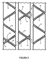
この問題を解決するために、本考案は、図3および図4に示されるように、2つの異なるグループの溝部または谷部のパターンを提供する。一方のパターンは一方向への螺旋状構成を備え、他方のパターンは、反対方向への螺旋状構成を備える。 In order to solve this problem, the present invention provides two different groups of groove or valley patterns, as shown in FIGS. One pattern has a spiral configuration in one direction and the other pattern has a spiral configuration in the opposite direction.
より正確には、櫛は、図1に示されるような全体的構成を有してもよいが、先行技術とは異なり、複数の溝部または谷部は少なくとも2グループの溝部または谷部を含む。すなわち、各々の歯部のまわりを螺旋状に第1の回転方向に延在する第1のグループの溝部4と、各々の歯部のまわりを螺旋状に、上記第1の回転方向と交差する第2の方向に延在する第2のグループの溝部12とである。溝部4のグループは、歯部の上方から見ると、時計回りの方向に回転することによって歯部に沿って下降し、第2のグループ12においては、溝部は、反対方向に回転しながら下降して、両方のグループの溝部を交差させて、歯部3同士の間の各隙間5内において両方向に鋭い端縁を規定する。
More precisely, the comb may have an overall configuration as shown in FIG. 1, but unlike the prior art, the plurality of grooves or valleys includes at least two groups of grooves or valleys. That is, the first group of grooves 4 extending in the first rotation direction spirally around each tooth portion, and the first rotation direction intersecting spirally around each tooth portion. And a second group of
溝部4および12は、互いに交差すると、隙間5の外側または隙間5の内側にランダムに位置し得る交差区域13を形成する。歯部同士の間の隙間5は0.05mmから0.1mmであってもよく、同じグループの溝部は、歯部のまわりを円周方向に延在し、0.5mm〜5mmの間隔を空けて配置される。螺旋状溝部の2つのグループが互いに反対方向に延在している構成により、幼虫「L」(図4を参照)を担持する毛髪11が尖った端縁6に接触する際に常に歯部3bまたは歯部3cから接触する、すなわち、毛髪が滑り抜けていく隙間5における側面側の歯部のいずれかから接触することが確実にされる。このようにして、尖った端縁6のいずれかによって確実に幼虫が捕らえられることとなる。図4においては、幼虫「L」は、途中で、歯部3bにおける2つの鋭い端縁6aおよび6bと、歯部3cにおける尖った端縁6cとに接触するだろう。幼虫は、下降させると、歯部3bの尖った端縁6dおよび歯部3cの尖った端縁6eに接触することとなる。これにより、幼虫「L」を捕らえて、患者または使用者の毛髪に張り付いている異物およびシラミと一緒に引きずり出せる確率が大幅に増大するだろう。
When the
また本考案に従うと、溝部4および溝部12は切断技術または好ましくは転造によって形成されてもよい。より正確には、本考案の別の局面に従うと、図6および図7に最もよく示されるように、各々の溝部または螺旋状の谷部5および12は、少なくとも一方側に、円筒形の歯部3の概して滑らかな表面の上に突出た突起14を有する。図5においては、明確にするために4つの溝部しか示されていないが、積層物および境界部14も図3および図4の溝部12に適用可能であることが分かる。好ましくは、2つの境界部14および15は、溝部4または12の両側に位置するように、溝部4または溝部12の両側に1つずつ設けられることとなるが、所望の効果を達成するために単一のフランジでも可能であることが明らかである。加えて、フランジ14および15は、所望の設計や、用いられる材料などに応じて、鋭い端縁または緩やかに丸みを帯びた端縁を規定し得る先端部16を有してもよい。
Also according to the present invention, the groove 4 and the
歯部は、たとえば50μm〜100μmの距離を空けて配置されてもよく、上記隆起した突起は、好ましくは0.005mmから0.04mm、より好ましくは最大距離0.01mmを空けて上記歯面「S」の上方に延在する。これらの円周方向の溝部は、0.5mmから4mmの距離を空けて配置されてもよく、上記螺旋状の溝部は0.5mmから4mmの螺旋ピッチを有してもよい。 The tooth portions may be arranged, for example, at a distance of 50 μm to 100 μm, and the raised protrusions are preferably 0.005 mm to 0.04 mm, more preferably a maximum distance of 0.01 mm, and the tooth surface “ Extends above "S". These circumferential grooves may be arranged at a distance of 0.5 mm to 4 mm, and the spiral grooves may have a helical pitch of 0.5 mm to 4 mm.
隣接する歯部の溝部は、隣接する歯部の突起14および15が図5に示されるようにずらされるかまたは互いに面するように配置されてもよい。いずれの場合も、2本の隣接する歯部9同士の間の距離は小さくなり、これにより、幼虫または異物17を保持する毛髪11の通過が制限されてしまうだろう。
The groove portions of adjacent tooth portions may be arranged such that adjacent
別の局面においては、本考案は、櫛1の歯部3上に溝部4、12および突起14、15を形成するための方法を提供する。実際には、先行技術の櫛歯上の溝部は、歯面を機械加工するための切削工具を使用することによって達成されるが、結果として、溝部が非常に粗くなってしまい、毛髪を研磨してしまうのに対して、本考案は、公知のシラミ用櫛の有する2つの問題をうまく解決する別の方法を用いている。1つの問題は溝部の摩耗性であり、もう1つの問題は、幼虫をより有効に捕らえるのに十分な組織が歯部に不足していることである。
In another aspect, the present invention provides a method for forming the
本考案のこの局面に従うと、切断ではなく転造技術を用いて溝部を作成する。より特定的には、歯部材料を変形させる段階が1回だけ実行される。この段階は、櫛歯の各々に対して転造工具17を作用させて、圧力を加えることによって上記溝部4、12を形成するステップを含む。上記圧力は、図6に示されるように、上記歯面「S」に対して傾斜させることができる力ベクトルFlに応じて加えられ、溝部に隣接する材料をその側面のうち少なくとも1つに向かって移動させることにより、少なくとも溝部のその側面に上記突起14を形成し得る。
According to this aspect of the invention, the groove is created using a rolling technique rather than cutting. More specifically, the step of deforming the tooth material is performed only once. This stage includes the step of forming the
代替的には、本考案の方法は、図7に示されるように、転造工具18を用いてもよい。転造工具18は、歯部3の表面に対して垂直な力F2を加えて、溝部に隣接する材料を溝部の両側に向かって移動させるようにして、溝部の両側に上記突起14および15を形成する。
Alternatively, the method of the present invention may use a rolling tool 18, as shown in FIG. The rolling tool 18 applies a force F2 perpendicular to the surface of the
この製造プロセスは冷間圧延であり、溝部またはスロット4、12は、たとえば、それが工具を通過する際にワイヤのまわりで工具を回転させることによって作製することができる。実際には、工具17または18は1つであってもまたは複数であってもよい。
This manufacturing process is cold rolling and the grooves or
本考案は、先行技術に勝る改善例を提示する。たとえば、アルゼンチン特許AR03275Blは、幼虫をその経路における90度のスリット内に落下させて、幼虫が歯部上の溝部内に入っている場合にはこの幼虫を捕らえることに成功している。1つまたは2つの突起14、15を備えている本考案では、幼虫に対する最も積極的作用を示す区域、すなわち突起および溝部、を拡張させることができる。さらに、追加のわなをもたらす突起を備えることもできる。このとき、幼虫は、同じ考案者による特許に記載される溝部に落下するよりもより頻繁に突起に衝突する。
The present invention presents an improvement over the prior art. For example, the Argentine patent AR03275Bl succeeds in dropping a larvae into a 90 degree slit in the path and catching the larvae when they are in a groove on the tooth. In the present invention with one or two
2つの効果が本考案の突起または起伏によって達成される。粗い区域が広くなるのに応じて幼虫が捕らえられる確率が高くなる。この場合、円筒の母線に沿っていくらか拡張させることで、幼虫と衝突し易くなっている。たとえば、幼虫の動きに対して90度の角度で突出する境界部により、その経路にいる幼虫が引きずり出されるおよび/または分解される。頭全体にこれらの櫛を通す進路に注意を払うことによって、毛髪上の幼虫に対する溝部および突起付き歯部の移動が、歯部に対して垂直な成分と、その軸の方向における別の成分とを有することが分かる。次いで、溝部に対する幼虫の複合的な動きは、その進路からほぼ90度となっている。すなわち、櫛を通すことによって、毛髪に付着した幼虫が突起または溝部に引っ掛けられる。 Two effects are achieved by the protrusions or undulations of the present invention. As the rough area becomes wider, the probability of catching larvae increases. In this case, it is easy to collide with the larvae by extending some along the cylindrical generatrix. For example, a boundary projecting at an angle of 90 degrees with respect to the larvae movement drags and / or breaks down the larvae in the path. By paying attention to the path of these combs throughout the head, the movement of the flutes and protruding teeth with respect to the larvae on the hair will cause a component perpendicular to the tooth and another component in the direction of its axis It can be seen that Next, the complex movement of the larvae with respect to the groove is approximately 90 degrees from the course. That is, by passing the comb, the larva attached to the hair is hooked on the protrusion or groove.
図5は、歯部の長手方向断面であって、突起および溝部によって引っ張られる毛髪に付着した幼虫と接触断面とを示す図である。この図に示されるように、各々の突起14および15の高さ「H」は0.04mmを超えないだろう。
FIG. 5 is a cross-sectional view in the longitudinal direction of the tooth portion, showing a larva attached to the hair pulled by the protrusion and the groove and a contact cross section. As shown in this figure, the height “H” of each
本考案の別の改善例は、製造プロセスにおいて切屑が除去されない場合に、歯部の材料が、転造圧力を受けて塑性状態となり、端縁上にまで運ばれてそこに堆積し、これにより、突起14および15を形成することである。したがって、このようにして得られた溝内面は摩擦を引起こさず、その突起は非常に積極的な作用を示す。
Another improvement of the present invention is that if the chips are not removed in the manufacturing process, the tooth material will be in a plastic state under rolling pressure and will be carried over the edge and deposited there, thereby Forming the
製造プロセスにおいて用いられる転造方法はまた、櫛の有効性についての重要な変動要素である、屈曲に対する歯部の抵抗性を向上させる。この向上は、結果として生じる切欠が、切屑を除去する場合と同様に材料の繊維を切断しないことによってもたらされる。 The rolling method used in the manufacturing process also improves the resistance of the teeth to bending, which is an important variable for comb effectiveness. This improvement is brought about by the resulting notch not cutting the fibers of the material in the same way as removing chips.
また本考案に従うと、溝部4および溝部12は切断技術または好ましくは転造によって形成されてもよい。より正確には、本考案の別の局面に従うと、図6および図7に最もよく示されるように、各々の溝部または螺旋状の谷部4および12は、少なくとも一方側に、円筒形の歯部3の概して滑らかな表面の上に突出た突起14を有する。図5においては、明確にするために4つの溝部しか示されていないが、積層物および境界部14も図3および図4の溝部12に適用可能であることが分かる。好ましくは、2つの境界部14および15は、溝部4または12の両側に位置するように、溝部4または溝部12の両側に1つずつ設けられることとなるが、所望の効果を達成するために単一のフランジでも可能であることが明らかである。加えて、フランジ14および15は、所望の設計や、用いられる材料などに応じて、鋭い端縁または緩やかに丸みを帯びた端縁を規定し得る先端部16を有してもよい。
Also according to the present invention, the groove 4 and the
Claims (15)
前記複数の溝部または谷部は、少なくとも2グループの溝部または谷部によって形成され、前記少なくとも2グループの溝部または谷部は、すなわち、各々の歯部のまわりを螺旋状に第1の回転方向に延在する第1のグループの溝部と、各々の歯部のまわりを螺旋状に、前記第1の回転方向と交差する第2の方向に延在する第2のグループの溝部とであり、前記溝部は、歯部の間の隙間の各々において両方向に尖った端縁を規定する、櫛。 A comb for treating head lice of the type including a grip handle, wherein a plurality of tooth portions protrude from the grip portion, and the tooth portions are arranged at a distance that allows a single hair to pass through the comb. Comprising rough means for holding and dragging lice and larvae present, said rough means comprising a plurality of continuous grooves or valleys defined on the surface of at least one longitudinal segment of each of said teeth With
The plurality of grooves or valleys are formed by at least two groups of grooves or valleys, and the at least two groups of grooves or valleys, that is, spirally around each tooth in the first rotational direction. A first group of grooves extending and a second group of grooves extending in a second direction that intersects the first rotational direction in a spiral fashion around each tooth. A groove is a comb that defines sharp edges in both directions in each of the gaps between the teeth.
前記櫛の前記歯部の各々に対して転造圧力工具を作用させて、前記歯面に対して傾斜した力ベクトルとして圧力を与えて前記溝部を形成し、前記溝部に隣接する材料を前記溝部の少なくとも一方側に向かって移動させるステップを含み、前記境界部は前記溝部の少なくとも前記一方側に形成される、方法。 A method for forming a boundary part and a groove part projecting on a tooth part of a comb according to any one of claims 1 to 13,
A rolling pressure tool is applied to each tooth portion of the comb to apply pressure as a force vector inclined with respect to the tooth surface to form the groove portion, and a material adjacent to the groove portion is used as the groove portion. The boundary portion is formed on at least one side of the groove portion.
Applications Claiming Priority (1)
| Application Number | Priority Date | Filing Date | Title |
|---|---|---|---|
| PCT/CL2013/000093 WO2015089682A1 (en) | 2013-12-19 | 2013-12-19 | Bidirectional comb for pediculosis and method for the production thereof |
Publications (1)
| Publication Number | Publication Date |
|---|---|
| JP3208806U true JP3208806U (en) | 2017-02-23 |
Family
ID=53401877
Family Applications (1)
| Application Number | Title | Priority Date | Filing Date |
|---|---|---|---|
| JP2016600086U Expired - Lifetime JP3208806U (en) | 2013-12-19 | 2013-12-19 | Bidirectional sweep type lice comb and method of manufacturing the same |
Country Status (7)
| Country | Link |
|---|---|
| JP (1) | JP3208806U (en) |
| BR (2) | BR112016014451A2 (en) |
| CZ (1) | CZ31020U1 (en) |
| ES (1) | ES1161208Y (en) |
| PT (1) | PT2015089682Y (en) |
| RU (1) | RU173356U1 (en) |
| WO (1) | WO2015089682A1 (en) |
Families Citing this family (2)
| Publication number | Priority date | Publication date | Assignee | Title |
|---|---|---|---|---|
| BE1024649B1 (en) * | 2017-06-20 | 2018-05-15 | Laboratoire Puressentiel S.A. | ANTI-LICE COMB |
| AR127462A1 (en) * | 2022-10-26 | 2024-01-24 | Assist Srl | COMB FOR THE TREATMENT OF PEDICULOSIS |
Citations (3)
| Publication number | Priority date | Publication date | Assignee | Title |
|---|---|---|---|---|
| CN201919967U (en) * | 2010-11-12 | 2011-08-10 | 李国锋 | Steel needle used for lice comb |
| JP2013511313A (en) * | 2009-11-23 | 2013-04-04 | サンス,ファン・マルティン | Comb for treating lice |
| US20130301292A1 (en) * | 2009-02-09 | 2013-11-14 | Carlos Jose Albaladejo Jimenez | Black light comb |
Family Cites Families (3)
| Publication number | Priority date | Publication date | Assignee | Title |
|---|---|---|---|---|
| US4807652A (en) * | 1987-09-14 | 1989-02-28 | American Comb Corp. | Comb |
| RU2003271C1 (en) * | 1991-03-18 | 1993-11-30 | Laptev Ilya I | Nap combing device |
| KR20090039024A (en) * | 2007-10-17 | 2009-04-22 | 정진언 | Comb |
-
2013
- 2013-12-19 BR BR112016014451A patent/BR112016014451A2/en active IP Right Grant
- 2013-12-19 WO PCT/CL2013/000093 patent/WO2015089682A1/en active Application Filing
- 2013-12-19 RU RU2016129538U patent/RU173356U1/en active
- 2013-12-19 CZ CZ2016-32584U patent/CZ31020U1/en not_active IP Right Cessation
- 2013-12-19 BR BR212016014451U patent/BR212016014451Y1/en active IP Right Grant
- 2013-12-19 JP JP2016600086U patent/JP3208806U/en not_active Expired - Lifetime
- 2013-12-19 ES ES201690004U patent/ES1161208Y/en not_active Expired - Fee Related
- 2013-12-19 PT PT2013000093U patent/PT2015089682Y/en active IP Right Grant
Patent Citations (3)
| Publication number | Priority date | Publication date | Assignee | Title |
|---|---|---|---|---|
| US20130301292A1 (en) * | 2009-02-09 | 2013-11-14 | Carlos Jose Albaladejo Jimenez | Black light comb |
| JP2013511313A (en) * | 2009-11-23 | 2013-04-04 | サンス,ファン・マルティン | Comb for treating lice |
| CN201919967U (en) * | 2010-11-12 | 2011-08-10 | 李国锋 | Steel needle used for lice comb |
Also Published As
| Publication number | Publication date |
|---|---|
| ES1161208Y (en) | 2016-10-10 |
| BR212016014451Y1 (en) | 2020-04-28 |
| BR112016014451A2 (en) | 2017-11-28 |
| WO2015089682A8 (en) | 2015-08-27 |
| ES1161208U (en) | 2016-07-19 |
| PT2015089682Y (en) | 2016-09-28 |
| RU173356U1 (en) | 2017-08-23 |
| WO2015089682A1 (en) | 2015-06-25 |
| CZ31020U1 (en) | 2017-09-19 |
Similar Documents
| Publication | Publication Date | Title |
|---|---|---|
| JP5559347B2 (en) | Comb for treating lice | |
| US20170332600A1 (en) | Multi-purpose grooming tools | |
| US8181304B1 (en) | Implement for brushing hair having a tangle reducing prong configuration | |
| US6575174B2 (en) | Hair grooming brush | |
| RU2745245C2 (en) | Hair brush | |
| CA2726681A1 (en) | Brush | |
| JP3208806U (en) | Bidirectional sweep type lice comb and method of manufacturing the same | |
| US8925560B2 (en) | Comb | |
| US7909042B2 (en) | Lice and nit removal comb with square shaped metal teeth | |
| CN104082170A (en) | Combing member and pet comber | |
| JP7054953B2 (en) | Comb for the treatment of pediculosis | |
| JP2017519116A (en) | Metal card wire | |
| WO2024088651A1 (en) | Comb for the treatment of pediculosis | |
| JP2019155069A (en) | Thinning scissor | |
| US20140261225A1 (en) | Pet grooming and dematting tool | |
| EA040236B1 (en) | PEDICULOSIS COMB | |
| NL1041329B1 (en) | Hairbrush. | |
| CA2856998C (en) | A comb | |
| JP2012005388A (en) | Component (tool) for pick up fallen hair of pets attached to comb | |
| JP3172834U (en) | Pet hair ski equipment | |
| TWM486314U (en) | Comb |
Legal Events
| Date | Code | Title | Description |
|---|---|---|---|
| A521 | Request for written amendment filed |
Free format text: JAPANESE INTERMEDIATE CODE: A523 Effective date: 20160819 |
|
| A711 | Notification of change in applicant |
Free format text: JAPANESE INTERMEDIATE CODE: A711 Effective date: 20161220 |
|
| A521 | Request for written amendment filed |
Free format text: JAPANESE INTERMEDIATE CODE: A821 Effective date: 20161220 |
|
| R150 | Certificate of patent or registration of utility model |
Ref document number: 3208806 Country of ref document: JP Free format text: JAPANESE INTERMEDIATE CODE: R150 |
|
| R250 | Receipt of annual fees |
Free format text: JAPANESE INTERMEDIATE CODE: R250 |
|
| R250 | Receipt of annual fees |
Free format text: JAPANESE INTERMEDIATE CODE: R250 |
|
| A623 | Registrability report |
Free format text: JAPANESE INTERMEDIATE CODE: A623 Effective date: 20210311 |
|
| R250 | Receipt of annual fees |
Free format text: JAPANESE INTERMEDIATE CODE: R250 |
|
| R250 | Receipt of annual fees |
Free format text: JAPANESE INTERMEDIATE CODE: R250 |
|
| EXPY | Cancellation because of completion of term |