JP3208742U - Segment hanging jig - Google Patents
Segment hanging jig Download PDFInfo
- Publication number
- JP3208742U JP3208742U JP2016005138U JP2016005138U JP3208742U JP 3208742 U JP3208742 U JP 3208742U JP 2016005138 U JP2016005138 U JP 2016005138U JP 2016005138 U JP2016005138 U JP 2016005138U JP 3208742 U JP3208742 U JP 3208742U
- Authority
- JP
- Japan
- Prior art keywords
- segment
- gravity
- jig
- suspension
- center
- Prior art date
- Legal status (The legal status is an assumption and is not a legal conclusion. Google has not performed a legal analysis and makes no representation as to the accuracy of the status listed.)
- Expired - Lifetime
Links
- 239000000725 suspension Substances 0.000 claims abstract description 49
- 238000002347 injection Methods 0.000 claims abstract description 45
- 239000007924 injection Substances 0.000 claims abstract description 45
- 230000005484 gravity Effects 0.000 claims abstract description 40
- 239000000463 material Substances 0.000 claims abstract description 22
- 230000002093 peripheral effect Effects 0.000 claims abstract description 6
- 238000003780 insertion Methods 0.000 claims description 5
- 230000037431 insertion Effects 0.000 claims description 5
- 238000000034 method Methods 0.000 description 10
- 210000002445 nipple Anatomy 0.000 description 9
- 229910000831 Steel Inorganic materials 0.000 description 5
- 239000010959 steel Substances 0.000 description 5
- 230000004927 fusion Effects 0.000 description 4
- 229910001315 Tool steel Inorganic materials 0.000 description 2
- 238000005452 bending Methods 0.000 description 2
- 238000004364 calculation method Methods 0.000 description 2
- 238000004519 manufacturing process Methods 0.000 description 2
- 229910001018 Cast iron Inorganic materials 0.000 description 1
- 238000010276 construction Methods 0.000 description 1
- 230000007423 decrease Effects 0.000 description 1
- 238000012986 modification Methods 0.000 description 1
- 230000004048 modification Effects 0.000 description 1
- 230000000149 penetrating effect Effects 0.000 description 1
- 230000003014 reinforcing effect Effects 0.000 description 1
- 239000004576 sand Substances 0.000 description 1
- 238000004088 simulation Methods 0.000 description 1
- 239000011800 void material Substances 0.000 description 1
- XLYOFNOQVPJJNP-UHFFFAOYSA-N water Substances O XLYOFNOQVPJJNP-UHFFFAOYSA-N 0.000 description 1
Images


Abstract
【課題】セグメントの荷ぶれの発生を低減することができるセグメント用吊り治具を提供する。【解決手段】セグメントの注入孔に取り付けてセグメントを吊り上げるセグメント用吊り治具1であって、前記注入孔に挿入される軸部2の外周面に、注入孔と螺合する螺旋突条が設けられ、前記軸部の上側に、軸部を支持する頭部3が設けられ、前記軸部が回転することにより注入孔の軸線方向に移動可能とされたネジ部と、前記ネジ部の上側に、セグメントを吊り上げるための吊持連結材を挿入する連結孔5を備えた連結部8とを有し、セグメントの重心の位置と注入孔の位置が異なるセグメントに吊り治具を取り付けた状態で、セグメントの重心の位置に連結孔を設けたことを特徴とする。【選択図】図1A segment hanging jig capable of reducing the occurrence of segment load is provided. A segment suspension jig 1 for lifting a segment by attaching it to an injection hole of a segment, wherein a spiral protrusion that is screwed into the injection hole is provided on an outer peripheral surface of a shaft portion 2 inserted into the injection hole. A head portion 3 that supports the shaft portion is provided above the shaft portion, and a screw portion that is movable in the axial direction of the injection hole by rotating the shaft portion; and an upper side of the screw portion. And a connecting portion 8 having a connecting hole 5 into which a suspension connecting material for lifting the segment is inserted, and with a hanging jig attached to the segment where the position of the center of gravity of the segment and the position of the injection hole are different, A connecting hole is provided at the position of the center of gravity of the segment. [Selection] Figure 1
Description
本考案は、吊り治具に関し、特に、セグメントを搬送するために用いるセグメント用吊り治具に関する。 The present invention relates to a hanging jig, and more particularly to a segment hanging jig used for transporting a segment.
本考案に係る吊り治具は、シールド工法に用いられるものである。 The hanging jig according to the present invention is used for a shield method.
シールド工法では、シールド掘削機の前面に設けたカッターヘッドによって地盤を掘削するとともに、地盤が崩れないように、掘削機の後方に設けたエレクターによって、セグメントをリング状に組み立てている。このシールド工法は、都市部などにおけるトンネルの構築に多用されている。 In the shield method, the ground is excavated by a cutter head provided in front of the shield excavator, and the segments are assembled in a ring shape by an erector provided behind the excavator so that the ground does not collapse. This shield method is often used for construction of tunnels in urban areas.
小径断面のシールドでは、セグメント搬送に際しては、次のように行う。
すなわち、トンネル抗口側から掘削機までセグメントを搬送するためのガイドレールを設けておき、このガイドレールに沿って自在に移動するホイストを取り付けおく。
所定位置において、作業員は、トンネル内に敷設した線路レールに沿って移動させたセグメント台車上の搬入されたセグメントを、ホイストによってその下端部に連結された吊り治具を介して、セグメントを吊り上げ保持し、シールド掘削機の後部まで延在する搬送ローラライン上にセグメントを移載し、さらに作業員は、移載したセグメント後端を手押しして、搬送ローララインに沿ってシールド機の後端部まで、セグメント運搬するようにしてある。
With a shield with a small-diameter cross section, segment transport is performed as follows.
That is, a guide rail for conveying the segment from the tunnel entrance side to the excavator is provided, and a hoist that moves freely along the guide rail is attached.
At a predetermined position, the worker lifts the segment carried on the segment carriage moved along the track rail laid in the tunnel via a lifting jig connected to the lower end of the segment by a hoist. Hold and transfer the segment onto the transport roller line that extends to the rear of the shield excavator, and the operator manually pushes the rear end of the transferred segment along the transport roller line. The segment is transported to the part.
従来から用いられている吊り治具101は、図18に示すように、セグメント注入孔115に挿入される。この吊り治具101は、注入孔115の壁面と螺合する軸部102と、この軸部102から上方へ向かって順に頭部103及び連結部108を有する。また、この連結部108には連結孔105が設けられる。この連結孔105が設けられる位置は、軸部102の中心軸線Y上である。すなわち、セグメント注入孔115の位置と吊り治具101の連結孔105の位置が同じになる。
The conventionally used hanging
前記セグメントが軸方向挿入型セグメントである場合、K型セグメントとB型セグメントの形状は台形であるため、セグメントの重心の位置とセグメントの注入孔の位置が異なる。このセグメントに従来の吊り治具を取り付けた場合、吊り治具の連結孔の位置とセグメントの重心の位置が異なることとなる。そのため、セグメントを吊り上げたホイストが、ガイドレールに沿って移動する際、セグメントの荷ぶれの発生する可能性がある。 When the segment is an axial insertion type segment, the shape of the K-type segment and the B-type segment is trapezoidal, so the position of the center of gravity of the segment and the position of the injection hole of the segment are different. When a conventional hanging jig is attached to this segment, the position of the connecting hole of the hanging jig and the position of the center of gravity of the segment are different. Therefore, when the hoist that lifts the segment moves along the guide rail, there is a possibility that the segment will be crushed.
したがって、本考案が解決しようとする主たる課題は、セグメントの荷ぶれの発生を低減し、安全に搬送できるようにすることにある。 Accordingly, the main problem to be solved by the present invention is to reduce the occurrence of segment spillage and to enable safe transportation.
本考案は、セグメントの注入孔に取り付けて前記セグメントを吊り上げるセグメント用吊り治具であって、前述した技術的課題を解決するために以下のように構成されている。すなわち、セグメントの注入孔に取り付けてセグメントを吊り上げるセグメント用吊り治具であって、前記注入孔に挿入される軸部の外周面に、注入孔と螺合する螺旋突条が設けられ、前記軸部の上側に、軸部を支持する頭部が設けられ、前記軸部が回転することにより注入孔の軸線方向に移動可能とされたネジ部と、前記ネジ部の上側に、セグメントを吊り上げるための吊持連結材を挿入する連結孔を備えた連結部とを有し、セグメントの重心の位置と注入孔の位置が異なるセグメントに吊り治具を取り付けた状態で、セグメントの重心の位置に連結孔を設けたことを特徴とする。 The present invention is a segment hanging jig that is attached to a segment injection hole and lifts the segment, and is configured as follows to solve the above-described technical problem. That is, a segment suspension jig for lifting a segment by being attached to an injection hole of a segment, wherein a spiral protrusion that is screwed into the injection hole is provided on an outer peripheral surface of a shaft portion that is inserted into the injection hole. A head portion that supports the shaft portion is provided above the portion, a screw portion that is movable in the axial direction of the injection hole by the rotation of the shaft portion, and for lifting the segment above the screw portion And a connecting part with a connecting hole for inserting the suspension connecting material, and connecting to the position of the center of gravity of the segment with the lifting jig attached to the segment where the position of the center of gravity of the segment and the position of the injection hole are different A hole is provided.
以下、この考案を構成要素に分けて説明する。吊り治具にはセグメントの自重や組立て時の衝撃によって強い曲げ応力がかかるため、曲げ強度の高い材料を用いることが好ましい。具体的には、工具鋼等の高い強度を有する鉄鋼を用いるのが好ましい。 Hereinafter, this device will be described by dividing it into components. Since a strong bending stress is applied to the hanging jig due to the weight of the segment or an impact during assembly, it is preferable to use a material having a high bending strength. Specifically, it is preferable to use steel having high strength such as tool steel.
吊り治具をセグメントに取り付けた状態で、吊り治具の連結部がセグメント内面から突出した状態を呈する。この連結部は、例えば二枚の板状部材を十字状に交差した形状であり、この板状部材には、板状部材を貫通する複数の連結孔が空けられている。セグメントを吊り上げる際は、この複数の連結孔のうち、セグメントの重心位置にある連結孔に吊持連結材の一端を挿入する。その後、吊持連結材を吊り上げることとなるが、吊持連結材を挿入した連結孔がセグメントの重心位置にあるため、セグメントの荷ぶれが抑えられ、安定した吊り上げを行うことができる。なお、前記吊持連結材としては、ワイヤロープやチェーン等の可撓性部材または組み立て材を例示することができる。 In a state where the suspension jig is attached to the segment, the connection portion of the suspension jig protrudes from the inner surface of the segment. The connecting portion has, for example, a shape in which two plate-like members are crossed in a cross shape, and the plate-like member has a plurality of connecting holes penetrating the plate-like member. When lifting the segment, one end of the suspension connection member is inserted into the connection hole at the center of gravity of the segment among the plurality of connection holes. Thereafter, the suspension connecting material is lifted. However, since the connection hole into which the suspension connecting material is inserted is located at the center of gravity of the segment, the segment can be prevented from being crushed and stable lifting can be performed. In addition, as said suspension connection material, flexible members, such as a wire rope and a chain, or an assembly material can be illustrated.
また、連結部に連結孔を1つ設けた吊り治具を、複数のセグメントの重心位置の違いに応じて複数種類用意してもよい。セグメントを吊り上げる際は、吊り上げるセグメントの重心位置に連結孔を設けた吊り治具を選択し、この選択した吊り治具をセグメントに取り付けて、吊り上げを行う。この場合も、連結孔がセグメントの重心位置にあるため、セグメントの荷ぶれが抑えられ、安定した吊り上げを行うことができる。 Moreover, you may prepare multiple types of suspension jig | tool which provided one connection hole in the connection part according to the difference in the gravity center position of several segments. When the segment is lifted, a lifting jig provided with a connection hole at the center of gravity of the lifting segment is selected, and the selected lifting jig is attached to the segment for lifting. Also in this case, since the connecting hole is located at the center of gravity of the segment, the segment can be prevented from being overloaded, and stable lifting can be performed.
前記軸部の下側を、注入孔のソケットやニップルと螺合させ、前記軸部の上側を、ナットと螺合させても良い。このようなダブルナット構造にすることにより、セグメントの揺れによって発生するネジ部の緩みを抑えることができる。 The lower side of the shaft portion may be screwed with a socket or a nipple of the injection hole, and the upper side of the shaft portion may be screwed with a nut. By adopting such a double nut structure, it is possible to suppress the loosening of the screw portion that occurs due to the shaking of the segment.
このナットには、ネジロックハンドルを設けることが好ましい。このネジロックハンドルによりナットの回転が容易となり、ナットの締め付けを強固なものにすることができる。このネジロックハンドルは、例えば、本体部と把持部から構成される。本体部は、例えば、環状に屈曲または多角形状に屈折させた棒状部材からなり、その中間部分が、ナットの外面を両脇から挟持する形態で固定される。また、この本体部は、吊り治具に対して略水平に取り付けられる。詳しくは、ハンドルの中間部から端部へかけて徐々に上向くような傾斜を設けると良い。セグメントの内部は、全体が緩やかに凹んだ形状であるため、ネジロックハンドルの端部に高さを設けることにより、セグメントの内部とネジロックハンドルの端部の接触を避けることができる。また、ネジロックハンドルの把持部は、例えば、棒状部材からなり、把持部の下端部が本体部の端部と融着等によって固定される。そして、把持部の下端部から上方へ延在する形態を示す。この把持部には、把持部の上端部が若干内側に傾くような傾斜を設けると良い。ネジロックハンドルの締付作業を行う者は、ネジロックハンドルの中間付近に立って締め付け作業をすることが多いため、このような傾斜を設けることにより、作業者が把持部を把持しやすくなるからである。 The nut is preferably provided with a screw lock handle. This screw lock handle facilitates the rotation of the nut and makes it possible to tighten the nut. The screw lock handle is composed of, for example, a main body portion and a grip portion. The main body portion is made of, for example, a rod-shaped member that is bent in an annular shape or refracted into a polygonal shape, and an intermediate portion thereof is fixed in such a manner as to sandwich the outer surface of the nut from both sides. Moreover, this main-body part is attached substantially horizontally with respect to a hanging jig. Specifically, it is preferable to provide an inclination that gradually increases from the middle part to the end part of the handle. Since the interior of the segment has a gently concave shape as a whole, contact between the interior of the segment and the end of the screw lock handle can be avoided by providing a height at the end of the screw lock handle. Further, the grip portion of the screw lock handle is made of, for example, a rod-like member, and the lower end portion of the grip portion is fixed to the end portion of the main body portion by fusion or the like. And the form extended upwards from the lower end part of a holding part is shown. The gripping portion may be provided with an inclination such that the upper end portion of the gripping portion is slightly tilted inward. This is because a person who performs the tightening operation of the screw lock handle often performs the tightening operation while standing near the middle of the screw lock handle, and thus providing the inclination makes it easier for the operator to grip the grip portion. .
本考案に係るセグメント用吊り治具を用いてセグメントを吊り上げる手順は、まず、
吊り治具の軸部の外周面に形成されたネジ山と、ネジロックハンドルを備えるナットの内周面に形成されたネジ溝を螺合させる。その結果、ナットが前記軸部の上部外周に取り付けられた状態となる。次に、ナットを取り付けた軸部をセグメント注入孔に挿入し、この軸部のねじ山と、セグメント注入孔のソケットやニップルに形成されたネジ溝を螺合させる。このようにして、セグメント注入孔に吊り治具の軸部が取り付けられる。その後、ネジロックハンドルを回転させ、ナットを更に締め付ける。この締め付けの際、第二のナットに強い回転力をかける必要があるが、ネジロックハンドルを回転させることで、この回転力を容易に発生させることができる。また、このようなダブルナット構造にすることで、ネジ部の緩みの発生を抑えることができる。その後、吊り治具の連結部に設けられた複数の連結孔のうち、セグメントの重心位置にある連結孔に、吊持連結材の一端または他端を接続する。
The procedure for lifting the segment using the segment lifting jig according to the present invention is as follows.
A screw thread formed on the outer peripheral surface of the shaft portion of the hanging jig and a screw groove formed on the inner peripheral surface of a nut provided with a screw lock handle are screwed together. As a result, the nut is attached to the upper outer periphery of the shaft portion. Next, the shaft part to which the nut is attached is inserted into the segment injection hole, and the thread of this shaft part is screwed into the thread groove formed in the socket or nipple of the segment injection hole. In this way, the shaft portion of the hanging jig is attached to the segment injection hole. Thereafter, the screw lock handle is rotated to further tighten the nut. At the time of this tightening, it is necessary to apply a strong rotational force to the second nut, but this rotational force can be easily generated by rotating the screw lock handle. Moreover, by using such a double nut structure, it is possible to suppress the occurrence of looseness of the threaded portion. Then, one end or the other end of the suspension connection member is connected to a connection hole located at the center of gravity of the segment among the plurality of connection holes provided in the connection portion of the hanging jig.
なお、連結部に挿入孔を1つ設けた吊り治具を、複数のセグメントの重心位置の違いに応じて複数種類用意した場合、各セグメントの種類に応じて、セグメントに取り付ける吊り治具の種類を変える。この場合、吊り治具の連結部には連結孔が1つ設けられているだけであるので、その連結孔に吊持連結材の一端または他端を接続する。 In addition, when multiple types of suspension jigs with one insertion hole in the connecting part are prepared according to the difference in the center of gravity of multiple segments, the type of suspension jig attached to the segment according to the type of each segment change. In this case, since only one connection hole is provided in the connection part of the suspension jig, one end or the other end of the suspension connection member is connected to the connection hole.
このようにして、吊り治具の連結部に吊持連結材を取り付けた後、この吊持連結材と連結するホイストによってセグメントを吊り上げる。そして、ホイストがガイドレールに沿って移動し、掘削機近傍までセグメントを搬送する。なお、運搬するセグメントの種類としては、例えば、軸方向挿入式の場合、A型セグメント、B型セグメント、K型セグメントを挙げることができる。これらの各セグメントの重心位置は夫々異なるため、各セグメントの重心位置にある連結孔に吊持連結材を接続するようにすると、セグメント運搬時の荷ぶれを抑えることができる。 Thus, after attaching a suspension connection material to the connection part of a suspension jig, a segment is lifted by the hoist connected with this suspension connection material. And a hoist moves along a guide rail and conveys a segment to the excavator vicinity. In addition, as a kind of segment to convey, in the case of an axial direction insertion type, an A type segment, a B type segment, and a K type segment can be mentioned, for example. Since the centroid positions of these segments are different from each other, if the suspension connection material is connected to the connection hole at the centroid position of each segment, it is possible to suppress the load during the transportation of the segments.
以上で説明したように、本考案に係るセグメント用吊り治具は、各セグメントの重心位置に対応して連結孔が設けられている。各セグメントの重心位置の連結孔に吊持連結材を連結することにより、セグメントの荷ぶれの発生を低減または防止し、安全に搬送できるようになる。 As described above, the segment suspension jig according to the present invention is provided with a connection hole corresponding to the position of the center of gravity of each segment. By connecting the suspension connecting material to the connecting hole at the center of gravity of each segment, the occurrence of segment load can be reduced or prevented, and the segment can be transported safely.
以下、本考案のセグメント用吊り治具の好適な実施形態について、図を用いて更に説明する。図1は、本考案の実施形態におけるセグメント用吊り治具を符号1で表したものである。 Hereinafter, preferred embodiments of the segment hanging jig of the present invention will be further described with reference to the drawings. FIG. 1 shows a segment hanging jig 1 according to an embodiment of the present invention.
(セグメント用吊り治具)
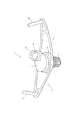
本実施形態におけるセグメント用吊り治具1は、図1に示すように、軸部2と頭部3からなるネジ部4と、連結部8から構成されている。軸部2は鋼製であり、図6に示すように、外周に螺旋状の突部が設けられている。また、この軸部2は円筒状または円錐状である。
(Suspension jig for segment)
As shown in FIG. 1, the segment hanging jig 1 according to this embodiment includes a screw portion 4 including a
頭部3は前記軸部2の上側に設けられ、軸部2を支持する。この頭部3は、軸部2と一体成形しても良いし、別々に製造し、後の製造過程で融着等により強く固着しても良い。この頭部3の径は、軸部2の上端部の径やセグメント注入孔15の径よりも大きい。また、セグメント10に吊り治具1を取り付けたとき、図3に示すように、軸部2はセグメント注入孔15内に収まるが、頭部3はセグメント注入孔15から上方へ突出した状態となる。
The
連結部8は、前記頭部3の上側に設けられ、吊り治具1に吊持連結材7を接続する際に用いられる。この連結部8も、頭部3や軸部2と一体成形で製造しても良いし、頭部3や軸部2と別々に製造し、後の製造過程で融着等により強く固着しても良い。
The connecting
実施例1においては、この連結部8の下端は、頭部3の上端と固着される。すなわち、連結部8を構成する2つの板状部材8A、8Bが、十字状に交差して、頭部3上に配置される。この板状部材8A、8Bの幅方向の長さは、頭部3の径の長さよりも長い。これは、頭部3よりも幅方向外側に、後述する連結孔5が設けられるからである。
In the first embodiment, the lower end of the connecting
また、図4に示すように、実施例1の板状部材8Aを正面から視たとき、七角形状を呈している。より詳しくは、四角形の三つの角部を面取りしたような面取り部8Xを形成している。このように、角部を鈍角にすることで、角部に作業者が触れた際の感触が穏やかなものとなる。
Moreover, as shown in FIG. 4, when the plate-shaped
実施例1において、この2つの板状部材8A、8Bの高さは互いに異なり、一方の板状部材8Aの高さは、他方の板状部材8Bの高さの約二倍となっている。具体的には、K型セグメント(10K)用の連結孔5K及びA型セグメント(10A)用の連結孔5Aを設けた板状部材8Aの高さは、B型セグメント(10B)用の連結孔5Bを設けた板状部材8Bの高さよりも高い。図1に示すように、板状部材8Bが板状部材8Aに設けた連結孔5Aの下方に位置するため、板状部材8Bと板状部材8Aの高さを同じにすると、その連結孔5A内を板状部材8Bが横切る状態となってしまう。このような状態では、板状部材8Aの連結孔5Aに吊持連結材7を接続することが困難となる。そこで、板状部材8Aの高さを板状部材8Bの高さよりも高く設定した。
In Example 1, the heights of the two plate-
板状部材8Aには、K型セグメント(10K)用の連結孔5KとA型セグメント(10A)用の連結孔5Aが設けられている。この連結孔5の直径Zは、4〜5cm程度にすることが好ましい。連結孔5の径Zが小さいと吊持連結材7を挿入しにくくなり、連結孔5の径Zが大きいと連結部8が大型化してしまうからである。第1実施例においては、A型セグメント(10A)の注入孔15が、A型セグメント(10A)の重心位置から5〜10cm程度離れた位置に設けられていると想定し、板状部材8Aに設けるA型セグメント(10A)用の連結孔5Aを、吊り治具1の軸部2の中心軸から5〜10cm程度離れた位置に設けている。すなわち、本実施例1に係るセグメント用吊り治具1をA型セグメント(10A)に取り付けた状態で、A型セグメント(10A)の重心にA型セグメント(10A)用の連結孔5Aを設けるようにする。
The plate-
また、第1実施例において、K型セグメント(10K)の注入孔15が、K型セグメント(10K)の重心位置よりも4〜5cm程度ずれた位置に設けられていると想定し、板状部材8Aに設けられるK型セグメント(10K)用の連結孔5Kを、前記軸部2の中心軸から4〜5cm程度ずれた位置に設けている。この場合もA型セグメント(10A)と同様に、本実施例1に係るセグメント用吊り治具1をK型セグメント(10K)に取り付けた状態で、K型セグメント(10K)の重心にK型セグメント(10K)用の連結孔5Kを設けるようにする。
Further, in the first embodiment, it is assumed that the
実施例1において、板状部材8Bは、板状部材8Aと直交している。詳しくは、板状部材8Bは、板状部材8Aによって左右に分断されている。そして、分断された左右の各板状部材8Bには、B型セグメント(10B)用の連結孔5がそれぞれ設けられる。すなわち、本実施例1に係る吊り治具1を平面から視たとき、図5に示すように、K型セグメント(10K)用の連結孔5Kが図面上側に位置し、図面右側にはB2型セグメント(10B2)用の連結孔5B2が設けられ、図面左側にはB1型セグメント(10B1)用の連結孔5B1が設けられる。B1型セグメント(10B1)とB2型セグメント(10B2)の形状は左右対象であるため、セグメント注入孔15の位置も左右対象となる。
In Example 1, the plate-
(セグメント注入孔)
前記セグメント注入孔15とは、裏込め注入材をテールボイドに注入するためにセグメント10に設けられた孔のことをいう。このセグメント注入孔15は、セグメント10の内周(15M)面と接するように配置されるソケットやニップル23を有する。このソケットやニップル23は、例えば、鋼管製または鋳鉄製である。このソケットやニップル23の地山側には、地山からの水や土砂の噴出を防止するため、逆止弁(図示しない)を設けるようにすると良い。
(Segment injection hole)
The
(ネジロックハンドル)
図8に示すように、吊り治具1の軸部2を、前記ソケットやニップル23に挿入することとなるが、その締結部の上方で、図7に示すようなナット22を軸部2に取り付けると良い。このナット22と、ソケットやニップル23によって、ダブルナットとなる。ダブルナットとすることにより、ネジ部4とソケットやニップル23の間のすべりを減らすことができ、回転ゆるみを防止することができる。
(Screw lock handle)
As shown in FIG. 8, the
ダブルナットの締付け方法は、まず吊り治具1の軸部2の先端側にナット22を取り付け、そのナット22を回転させて、軸部2の頭部3側へ移動させる。次に、吊り治具1の軸部2をソケット等23に挿入して、締め付けを行う。次に、軸部2の頭部3側へ移動させたナット22の締め付けを行う。その後、ナット22を固定した状態で、軸部2をソケット等23に対してゆるめ方向へ回転させて、頭部3側のナット22と先端側のソケット等23がねじ面で圧着される状態まで締め付ける。
As a method of tightening the double nut, first, a
図9や図10に示すように、前記ナット22の外面に、ネジロックハンドル6を取り付けると良い。一般的に、前記ナット22の締め付けは、スパナやメガネレンチ等の工具を用いて強く締め付ける必要がある。しかし、このネジロックハンドル6を設けることで、ナット22の締め付けが容易になるとともに、スパナ等を用いる場合と比べて、より強く締め付けを行うことができる。なお、このネジロックハンドル6を回転させる際には、強い荷重がかかる。そのため、ネジロックハンドル6の素材として、工具鋼等の高い強度を有する素材を用いることが好ましい。
As shown in FIGS. 9 and 10, a screw lock handle 6 may be attached to the outer surface of the
前述のように、セグメント10を水平に吊るためには、セグメント10の重心位置に吊り治具1の連結孔5を位置させる必要がある。そのためには、(1)吊り治具1の連結孔5がセグメント10の種類に応じて偏心していること、(2)セグメント10の種類に応じて、吊り治具1の向きを一定の方向に固定すること、が必要となる。そこで、前記ネジロックハンドル6を設けることで、前記(2)の要請に応えることができる。
As described above, in order to suspend the
詳述すれば、前記ダブルナットの締付け工程の最終段階で、軸部2をソケット等23に対してゆるめ方向へ回転させる。このときの移動量を考慮して、ナット22を一定の強さまで締付ける。このとき、ネジロックハンドル6を設けることにより、ナット22の締め付け量が調整しやすくなる。その結果、ダブルナットの締付けを終えた段階で、吊り治具1の連結孔5をセグメント10の重心位置に確実に位置させることができる。
More specifically, in the final stage of the double nut tightening process, the
前記ネジロックハンドル6は、例えば、図9や図10のように、本体部6Aと把持部6Bから構成される。本体部6Aは、例えば、棒状の部材からなり、全体の形状を環状または多角形状にすることができる。すなわち、本体部6Aの中間部分が、吊り治具1の頭部3を両脇から挟持するように固定される。そして、本体部6Aの中間部から先端側へ向かって、相対する棒状体の距離が次第に狭まるように延在し、本体部6Aの先端付近では、相対する棒状体が一つに結合されている。なお、前記先端部に作業者が接触する可能性を考慮して、前記先端部を尖らせるよりも、半円弧状としたほうが良い。ただし、後述するように、本体部6Aの先端側内縁と接触するように把持部6Bを設けるため、先端部の内角を狭くした方がよい。一方、本体部6Aの先端側において、ネジロックハンドル6の強度を上げるため、相対する棒状体間を橋渡しするように、架橋部6Cを設けると良い。なお、ネジロックハンドル6は、吊り治具1の頭部3を挟んで左右対象にすると良い。
The screw lock handle 6 includes a
また、前記本体部6Aを断面から視たとき、本体部6Aは吊り治具1に対して略水平に取り付けられている。すなわち、本体部6Aの中間部が吊り治具1の頭部3に固定され、そこから本体部6Aの先端側へ向かうに連れて、次第に上方へ傾く傾斜を設けると良い。セグメント10の内面11は、図2に示すように、全体に緩やかに凹んだ形状になっていることが多いため、ネジロックハンドル6の本体部6Aの先端側に高さを設けることにより、図3に示すように、セグメント10の内面11とネジロックハンドル6の先端部との接触を避けることができる。そのため、本体部6Aの前記傾斜角度は、セグメント10の内面11の傾斜角度よりも大きいほうが良い。
Further, when the
また、ネジロックハンドル6には把持部6Bが設けられる。この把持部6Bは、作業者によって把持される部分であり、ネジロックハンドル6を回転させる際に用いられる。この把持部6Bは、例えば、棒状の部材からなり、その下端部が本体部6Aの先端部内縁と固定される。ネジロックハンドル6を回転させた際、この把持部6Bが本体部6Aから外れてしまわないように、本体部6Aと把持部6Bの固定は、融着等によって強固に行われると良い。また、この把持部6Bは、本体部6Aと固定した下端部から、上方へ延在する形態を示す。そして、この把持部6Bには、上端側が内側へ若干傾くような傾斜を設け、作業者が把持しやすいようにすると良い。
The screw lock handle 6 is provided with a
(吊り上げ工程)
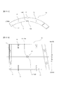
本考案に係る吊り治具1を用いて、コンクリートセグメント10を吊り上げる過程を説明する。なお、セグメント10の種類には、鉄骨コンクリート製、鋼製、ダクタイル製などがあるが、本考案の吊り上げ対象は、主としてコンクリート製のセグメント10である。このコンクリートセグメント10は、図2に示すように、トンネルの内壁と当接する外面13と、この外面13の側方に位置する継手面12と、外面13と反対の位置にある内面11からなる。継手面12には、隣り合うセグメント10を繋げるための継手ボルト16、継手ボルト孔14および継手板17が設けられる。また、セグメント10の内面11の中央付近から外面13へかけて注入孔15が設けられる。このコンクリートセグメント10は全体がコンクリートで形成され、その形態を維持するために、その内部には複数の鉄筋が交差するように配置される。
(Lifting process)
A process of lifting the
本考案に係る吊り治具1を取り付けるセグメント10としては、例えば、図12〜図14に示すように、A1型セグメント(10A1)、A2型セグメント(10A2)、B1型セグメント(10B1)、B2型セグメント(10B2)、頂点付近で最後に組み立てられるK型セグメント(10K)を挙げることができる。これらのセグメント10は、形状と重心位置がそれぞれ異なり、注入孔15の設けられた位置が、セグメント10の重心位置にあるとは限らない。そこで、本考案に係る吊り治具1を用いて、セグメント10の重心位置に吊持連結材7を接続することで、セグメント10運搬時の荷ぶれ発生を抑えることができる。なお、図11に示したA1型セグメント(10A1)とA2型セグメント(10A2)は同じ形状であり、B1型セグメント(10B1)とB2型セグメント(10B2)は左右対称の形状である。
As the
このような各セグメント10は、まず、外面13を下方に向けた状態で台車に積み重ねられ、既設トンネル内に搬入される。次に、搬入されたセグメント10に、本考案に係る吊り治具1を取付ける。すなわち、セグメント10の内面11の中央付近に形成されたセグメント注入孔15に吊り治具1を挿入する。ネジロックハンドル6を有するナット22を用いる場合は、ネジロックハンドル6の把持部6Bを把持し、これを回転させる。ダブルナットにすることにより、ネジの緩みを防止することができる。
Each
セグメント10に吊り治具1を取り付けた状態を図3に示す。図3において、ネジ部4の軸部2が挿入孔と締結され、そこから上方へ向かって順に、ネジロックハンドル6を備えたナット22、ネジ部4の頭部3、吊り治具1の連結部8がセグメント10の内面11から突出している。
A state in which the hanging jig 1 is attached to the
セグメント10に吊り治具1を取り付けた後は、吊り治具1の連結部8に吊持連結材7を繋げる。すなわち、連結部8に空けられた複数の連結孔5のうち、任意の連結孔5に吊持連結材7を挿入する。複数の連結孔5のうち、どの連結孔5に吊持連結材7を挿入するかは、セグメント10に吊り治具1を取り付けた状態で、セグメント10の重心位置を起点として、セグメント10の内面11に対して垂線上の位置にある連結孔5を選択する。
After attaching the suspension jig 1 to the
なお、連結孔5の位置を決める方法は、例えば、各セグメント10に設けられる注入孔15の位置と重心の位置との間の距離や、注入孔15の位置から見た重心のある方向を計算により求める。そして、吊り治具1をセグメント10に装着した状態をシミュレーションにより求め、前記の計算により求めた距離及び方向に連結孔5を設けるようにする。このようにして設けた連結孔5は、そのセグメント10の重心位置を起点として、セグメント10の内面11に対して垂線上に位置する。また、A1型セグメント(10A1)、A2型セグメント(10A2)、B1型セグメント(10B1)、B2型セグメント(10B2)、K型セグメント(10K)等のセグメント10毎に前記の計算を行うことで、連結部8には、各セグメント10の重心位置に対応した複数の連結孔5が形成される。
The method for determining the position of the connecting
なお、吊り治具1の連結部8と吊持連結材7の連結方法は、例えば、吊持連結材7の下端に、U字状の本体21Aとその本体21Aの両端部を橋渡しする棒状体21Bとからなる連結具21を設け、その連結具21の棒状体21Bを吊り治具1の連結孔5に通すことで、連結することができる。
In addition, the connection method of the
このように吊り治具1と吊持連結材7を連結した後、前記吊持連結材7の上端をホイストと結合する。そして、ホイストによってセグメント10を吊り上げ、既設トンネルの上端に敷設したガイドレールに沿って、ホイストを切羽近傍まで移動する。このホイストの移動により、吊り上げられたセグメント10が切羽近傍まで運ばれる。前記のとおり、セグメント10の重心位置の連結孔5に吊持連結材7を連結しているため、セグメント10の運搬の際の荷ぶれの発生を抑えることができ、セグメント10の運搬作業を適切に安定して行うことが可能となる。切羽近傍まで運ばれたセグメント10は任意の位置に荷下ろしされ、吊り治具1がセグメント10から取り外される。その後、シールド掘削機の後方に設けたエレクターにより、図11に示すように、セグメント10がリング状に組み立てられる。
After connecting the suspension jig 1 and the
(実施例2)
本考案に係る吊り治具1の実施例2として、図15に示すような吊り治具1を用いることができる。すなわち、吊り治具1の連結部8が、ネジ部4の頭部3から上方へ突出する複数の突状部材8Cから構成され、各突状部材8Cに連結孔5を設けるようにしても良い。
(Example 2)
As Example 2 of the hanging jig 1 according to the present invention, a hanging jig 1 as shown in FIG. 15 can be used. That is, the connecting
(実施例3)
また、本考案に係る吊り治具1の実施例3として、図16および図17に示すような吊り治具1を用いても良い。すなわち、吊り治具1の連結部8が、ネジ部4の頭部3から上方へ突出する1つの突状部材8Cから構成され、この突状部材8Cに1または2以上の連結孔5が設けられる。前記のように、セグメント10の形状によって重心の位置が異なるため、図16や図17のように、連結孔5の位置が異なる吊り治具1を複数用意し、セグメント10の重心位置によって取り付ける吊り治具1の種類を変えるようにする。なお、実施例3のような吊り治具1を用いても良いが、実施例1や実施例2のような吊り治具1は、全てのセグメント10に取り付けることができるため、利便性が高い。
(Example 3)
Moreover, you may use the hanging jig 1 as shown in FIG. 16 and FIG. 17 as Example 3 of the hanging jig 1 which concerns on this invention. That is, the connecting
以上のように、本考案においては、セグメント10の重心位置に連結孔5を設けるようにすれば良く、このことを満たすその他の種々の変形例も本考案の技術的範囲に包含される。
As described above, in the present invention, the
1 (本考案に係る)吊り治具
2 軸部
2U (軸部の)上部ネジ山
2D (軸部の)下部ネジ山
3 頭部
4 ネジ部
5 連結孔
5A A型セグメント用の連結孔
5B1 B1型セグメント用の連結孔
5B2 B2型セグメント用の連結孔
5K K型セグメント用の連結孔
6 ネジロックハンドル
6A (ネジロックハンドルの)本体部
6B (ネジロックハンドルの)把持部
6C (ネジロックハンドルの)架橋部
7 吊持連結材
8 連結部
8A 板状部材
8B 板状部材
8C 突状部材
8X 連結部の面取り部分
10 セグメント
10A A型セグメント
10A1 A1型セグメント
10A2 A2型セグメント
10B B型セグメント
10B1 B1型セグメント
10B2 B2型セグメント
10K K型セグメント
11 (セグメントの)内面
12 (セグメントの)継手面
13 (セグメントの)外面
14 継手ボルト孔
15 (セグメントの)注入孔
15M (注入孔の)内周
15N (注入孔の)外周
16 継手ボルト
17 継手板
18 シール溝
21 連結具
21A (連結具の)本体
21B (連結具の)棒状体
22 ナット
23 ソケットまたはニップル
101 (従来の)吊り治具
102 軸部
103 頭部
104 ネジ部
105 連結孔
108 連結部
110 セグメント
111 (セグメントの)内面
113 (セグメントの)外面
115 (セグメントの)注入孔
Y 軸部の中心軸線
Z 連結孔の直径
θ セグメントリングの中心を通る垂直線と、
セグメントリングの中心とK型セグメントの中央を結ぶ線との間の角度
DESCRIPTION OF SYMBOLS 1 Suspension jig | tool (according to this invention) 2 Shaft part 2U Upper screw thread 2D (Shaft part) Lower screw thread 3 Head 4 Screw part 5 Connection hole 5A Connection hole for A type segment 5B1 B1 Connecting hole for mold segment 5B2 Connecting hole for B2 type segment 5K Connecting hole for K type segment 6 Screw lock handle 6A Body part of screw lock handle 6B Grasping part of screw lock handle 6C Bridge part of screw lock handle 7 Suspended connecting material 8 Connecting portion 8A Plate member 8B Plate member 8C Protruding member 8X Chamfered portion of connecting portion 10 Segment 10A A type segment 10A1 A1 type segment 10A2 A2 type segment 10B B type segment 10B1 B1 type segment 10B2 B2 type Segment 10K K-type segment 11 (Segment) inner surface 12 (Seg Joint surface 13 (segment) outer surface 14 joint bolt hole 15 (segment) injection hole 15M (injection hole) inner periphery 15N (injection hole) outer periphery 16 joint bolt 17 joint plate 18 seal groove 21 connector 21A (Connector) main body 21B (connector) rod-like body 22 nut 23 socket or nipple 101 (conventional) lifting jig 102 shaft 103 head 104 screw part 105 connecting hole 108 connecting part 110 segment 111 (segment) Inner surface 113 (Segment) Outer surface 115 (Segment) injection hole Y Center axis of axis Z Z Diameter of connecting hole θ Vertical line passing through the center of segment ring,
Angle between the center of the segment ring and the line connecting the center of the K-shaped segment
Claims (4)
前記注入孔に挿入される軸部の外周面に、注入孔と螺合する螺旋突条が設けられ、前記軸部の上側に、軸部を支持する頭部が設けられ、前記軸部が回転することにより注入孔の軸線方向に移動可能とされたネジ部と、
前記ネジ部の上側に、セグメントを吊り上げるための吊持連結材を挿入する連結孔を備えた連結部とを有し、
セグメントの重心の位置と注入孔の位置が異なるセグメントに吊り治具を取り付けた状態で、セグメントの重心の位置に連結孔を設けたことを特徴とするセグメント用吊り治具。 A segment hanging jig that lifts the segment by attaching it to the injection hole of the segment,
A spiral protrusion that is screwed into the injection hole is provided on the outer peripheral surface of the shaft portion that is inserted into the injection hole, and a head portion that supports the shaft portion is provided above the shaft portion, and the shaft portion rotates. A threaded portion that is movable in the axial direction of the injection hole by
On the upper side of the threaded portion, and a connecting portion having a connecting hole for inserting a suspension connecting material for lifting the segment,
A segment suspension jig characterized in that a connecting hole is provided at the position of the center of gravity of a segment in a state where the suspension jig is attached to a segment where the position of the center of gravity of the segment differs from the position of the injection hole.
前記連結部には、複数のセグメントの異なる重心位置に対応して複数の連結孔が設けられ、
セグメントを吊り上げるときに、連結部に設けられた複数の連結孔のうち、吊り上げるセグメントの重心に位置する連結孔に吊持連結材を挿入する請求項1記載のセグメント用吊り治具。 The segment hanging jig can be attached to a plurality of segments having different positions of the center of gravity,
The connecting portion is provided with a plurality of connecting holes corresponding to the positions of the different centers of gravity of the plurality of segments,
The segment lifting jig according to claim 1, wherein when the segment is lifted, the suspension connecting member is inserted into a connecting hole located at the center of gravity of the lifting segment among the plurality of connecting holes provided in the connecting portion.
セグメントを吊り上げるときに、吊り上げるセグメントの重心位置に連結孔を設けた吊り治具が用いられる請求項1記載のセグメント用吊り治具。 Plural types of suspension jigs provided with one insertion hole in the connecting portion are prepared according to the difference in the center of gravity position of the plurality of segments,
The segment lifting jig according to claim 1, wherein when the segment is lifted, a lifting jig provided with a connecting hole at the center of gravity of the lifting segment is used.
前記ナットは、ネジロックハンドルを備え、
前記ネジロックハンドルは、
環状に屈曲または多角形状に屈折させた棒状部材からなり、その中間部分がナットを両側から挟持した状態で固定される本体部と、
下端部が本体部の先端部と固定され、前記下端部から上方へ延在する棒状部材からなる把持部とを有する請求項1〜3のいずれか1項に記載のセグメント用吊り治具。 The shaft portion of the screw portion is screwed with the nut on the upper end side from the position screwed with the injection hole,
The nut includes a screw lock handle;
The screw lock handle is
A main body portion that is formed of a rod-shaped member that is bent in an annular shape or refracted into a polygonal shape, the intermediate portion of which is fixed in a state where the nut is sandwiched from both sides,
The segment suspension jig according to any one of claims 1 to 3, further comprising: a grip portion made of a rod-like member that has a lower end portion fixed to a distal end portion of the main body portion and extends upward from the lower end portion.
Priority Applications (1)
| Application Number | Priority Date | Filing Date | Title |
|---|---|---|---|
| JP2016005138U JP3208742U (en) | 2016-10-25 | 2016-10-25 | Segment hanging jig |
Applications Claiming Priority (1)
| Application Number | Priority Date | Filing Date | Title |
|---|---|---|---|
| JP2016005138U JP3208742U (en) | 2016-10-25 | 2016-10-25 | Segment hanging jig |
Related Parent Applications (1)
| Application Number | Title | Priority Date | Filing Date |
|---|---|---|---|
| JP2013226843A Continuation JP2015086611A (en) | 2013-10-31 | 2013-10-31 | Suspension tool for segment |
Publications (1)
| Publication Number | Publication Date |
|---|---|
| JP3208742U true JP3208742U (en) | 2017-02-16 |
Family
ID=58043377
Family Applications (1)
| Application Number | Title | Priority Date | Filing Date |
|---|---|---|---|
| JP2016005138U Expired - Lifetime JP3208742U (en) | 2016-10-25 | 2016-10-25 | Segment hanging jig |
Country Status (1)
| Country | Link |
|---|---|
| JP (1) | JP3208742U (en) |
-
2016
- 2016-10-25 JP JP2016005138U patent/JP3208742U/en not_active Expired - Lifetime
Similar Documents
| Publication | Publication Date | Title |
|---|---|---|
| US8172289B2 (en) | Releasable lifting link | |
| JP2645646B2 (en) | Lifting and carrying hardware for heavy loads such as concrete parts | |
| US20190031473A1 (en) | Lifting fastener | |
| JP5004144B1 (en) | Tension tool | |
| JP3208742U (en) | Segment hanging jig | |
| JP2015086611A (en) | Suspension tool for segment | |
| US10196250B2 (en) | Bi-pod rescue strut system | |
| US11174133B2 (en) | Transport apparatus for assembly component and method of using transport apparatus | |
| JP6820605B2 (en) | How to transport hanging tools and heavy objects | |
| JP5958622B1 (en) | Self-supporting retaining wall block and retaining wall construction method using the same | |
| KR101310847B1 (en) | Moving device for supporter of mold | |
| JP3109069U (en) | Steel hanger | |
| CN206828926U (en) | A kind of both sides of the road limiting structure of highway engineering construction | |
| CN209479730U (en) | A kind of rickshaw for building | |
| JP2019206313A (en) | Loading trailer | |
| CN205591566U (en) | Reinforcing bar is transported and butt joint installation device | |
| JP6975577B2 (en) | Elevated structure and its construction method | |
| CN212427170U (en) | Fixing device of stake for building | |
| JP7190895B2 (en) | Split type utility pole joining tool and joining method | |
| CN210326949U (en) | Cable and safety device for cable core protection | |
| KR102064291B1 (en) | Mechanical Twin Tongs For Gripping Of The Level Difference Product | |
| KR20170089290A (en) | Apparatus for a clamping of a hoist jig | |
| WO2014080169A1 (en) | Handling member for transporting an elongate article | |
| JP2023167089A (en) | Ring joint | |
| JPH0715920Y2 (en) | Segment grip |
Legal Events
| Date | Code | Title | Description |
|---|---|---|---|
| A521 | Request for written amendment filed |
Free format text: JAPANESE INTERMEDIATE CODE: A821 Effective date: 20161025 |
|
| A521 | Request for written amendment filed |
Free format text: JAPANESE INTERMEDIATE CODE: A523 Effective date: 20161221 |
|
| R150 | Certificate of patent or registration of utility model |
Ref document number: 3208742 Country of ref document: JP Free format text: JAPANESE INTERMEDIATE CODE: R150 |
|
| R250 | Receipt of annual fees |
Free format text: JAPANESE INTERMEDIATE CODE: R250 |
|
| R250 | Receipt of annual fees |
Free format text: JAPANESE INTERMEDIATE CODE: R250 |
|
| R250 | Receipt of annual fees |
Free format text: JAPANESE INTERMEDIATE CODE: R250 |
|
| R250 | Receipt of annual fees |
Free format text: JAPANESE INTERMEDIATE CODE: R250 |
|
| EXPY | Cancellation because of completion of term |