JP7190895B2 - Split type utility pole joining tool and joining method - Google Patents
Split type utility pole joining tool and joining method Download PDFInfo
- Publication number
- JP7190895B2 JP7190895B2 JP2018245310A JP2018245310A JP7190895B2 JP 7190895 B2 JP7190895 B2 JP 7190895B2 JP 2018245310 A JP2018245310 A JP 2018245310A JP 2018245310 A JP2018245310 A JP 2018245310A JP 7190895 B2 JP7190895 B2 JP 7190895B2
- Authority
- JP
- Japan
- Prior art keywords
- joining
- utility pole
- pillar
- utility
- column
- Prior art date
- Legal status (The legal status is an assumption and is not a legal conclusion. Google has not performed a legal analysis and makes no representation as to the accuracy of the status listed.)
- Active
Links
Images


Description
本発明は、分割型電柱をフランジ部同士の突き合わせおよびボルト締めにより接合する分割型電柱の接合工具および接合方法に関する。 TECHNICAL FIELD The present invention relates to a split utility pole joining tool and joining method for joining split utility poles by butting flanges together and bolting.
一般的な電柱はコンクリート製の一本物であるが、この場合、高経年化に伴う電柱の建て替え時や新設時における運搬費用が増加したり、建柱作業で防護範囲が拡大したり、障害物を避け難い。また、電柱の撤去時、運搬規制による電柱切断費用や作業時間が増加したりしている。 A general utility pole is a single piece made of concrete, but in this case, transportation costs increase when the utility pole is rebuilt or newly installed due to aging, the protection range expands during the pole erection work, and obstacles hard to avoid. In addition, when removing utility poles, transportation regulations increase utility pole cutting costs and work hours.
そこで、電柱の建て替え時や新設時における運搬費用、建柱作業での防護範囲の縮小や障害物回避の容易性、また、電柱の撤去時における電柱切断費用や作業時間を削減するため、近年では、一本物の電柱に代わって、分割型電柱が導入されつつある(例えば、特許文献1参照)。 Therefore, in recent years, in order to reduce transportation costs when rebuilding or installing utility poles, reduce the protection range and ease of avoiding obstacles during pole erection work, and reduce utility pole cutting costs and work time when removing utility poles. A segmented utility pole is being introduced instead of a single utility pole (see, for example, Patent Document 1).
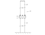
分割型電柱12は、図11に示すように、一端にフランジ部13,14を有する上部柱15および下部柱16からなり、上部柱15のフランジ部13と下部柱16のフランジ部14とを突き合わせてボルト締めすることにより、上部柱15と下部柱16とを接合した構造を具備する。
As shown in FIG. 11, the split-
上部柱15および下部柱16の両フランジ部13,14には、図12に示すように、ボルト締め用のボルト孔17,18が円周方向複数箇所に等間隔で形成されている。
As shown in FIG. 12,
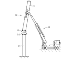
分割型電柱12の建柱作業では、柱上接合工法と地上接合工法の二種類がある。柱上接合工法は、図13に示すように、上部柱15と下部柱16とを柱上で接合する。地上接合工法は、図14に示すように、上部柱15と下部柱16とを地上で接合する。
There are two types of pole erection work for the split-type utility pole 12: a pole top joint method and a ground joint method. As shown in FIG. 13, in the column-top joining method, the
柱上接合工法は、図13に示すように、穴掘り建柱車と称する作業車両19により上部柱15を吊り上げ、地上に予め建柱された下部柱16の上に建柱する。
As shown in FIG. 13, in the pole-top joining method, an
この状態で、下部柱16のフランジ部14に対して上部柱15のフランジ部13を突き合わせて両フランジ部13,14でボルト締めすることにより、下部柱16に対して上部柱15を接合する。
In this state, the
地上接合工法は、図14に示すように、地上に配置された支持台20上に下部柱16を水平状態に載置する。そして、作業車両19により上部柱15を吊り上げて下部柱16の側方に水平状態で配置する。
In the ground joining method, as shown in FIG. 14, the
このように、上部柱15を吊り上げた状態で、下部柱16のフランジ部14に対して上部柱15のフランジ部13を突き合わせてボルト締めすることにより、下部柱16に対して上部柱15を接合する。
In this way, the
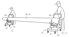
電柱12は、垂直に建柱する以外に、斜めに建柱する場合がある。つまり、図15に示すように、垂直な電柱12を補強する支柱として、垂直な電柱12に対して斜めに電柱12を建柱する。この支柱工事では、電柱12を斜めに建柱するため、上部柱15と下部柱16とを地上で接合する地上接合工法が必須である。
The
上部柱15と下部柱16とを地上で接合する従来の地上接合工法は、図16~図20に示す要領でもって以下のように行われる。
A conventional above-ground joining construction method for joining the
まず、図16に示すように、作業車両19(穴掘り建柱車)により下部柱16を吊り上げて運搬車両から降ろし、作業車両19により下部柱16を吊り上げた状態で、地上に配置された支持台20上に水平状態で載置する。
First, as shown in FIG. 16, the
一方、図17に示すように、作業車両19により上部柱15を吊り上げ、地上に予め配置された下部柱16の側方に水平状態で配置する。上部柱15の吊り上げ状態で、下部柱16のフランジ部14に対して上部柱15のフランジ部13を突き合わせる。
On the other hand, as shown in FIG. 17, the
その上で、図18に示すように、上部柱15の吊り上げ状態で、下部柱16に対して上部柱15を上下動させて高さ調整すると共に、下部柱16に対して上部柱15を軸中心で回転させる。
Then, as shown in FIG. 18, in the lifted state of the
上部柱15の高さ調整により、下部柱16のフランジ部14に対して上部柱15のフランジ部13を上下方向で位置合わせする。上部柱15の回転により、下部柱16のフランジ部14に対して上部柱15のフランジ部13を周方向で位置合わせする。
By adjusting the height of the
この位置合わせにより、下部柱16のフランジ部14のボルト孔18と上部柱15のフランジ部13のボルト孔17を一致させる(図12参照)。両フランジ部13,14のボルト孔17,18を一致させた状態で、両フランジ部13,14をボルト締めする。このボルト締めにより、下部柱16に対して上部柱15を接合する。
By this alignment, the
この時、吊り上げ状態にある上部柱15という重量物の直下作業となることから、作業の安全性を確保するため、フランジ部13,14の下方に位置するボルト孔17,18についてはボルト締めしないようにしている。
At this time, since the work is performed directly under the heavy object of the
両フランジ部13,14をボルト締めした後、図19に示すように、上部柱15と地上との間に支持台21を挿入配置する。その上で、作業車両19のワイヤによる吊り上げ状態を一旦緩める。
After both the
その後、図20に示すように、作業車両19のワイヤ操作により上部柱15を吊り上げて軸中心で回転させる。上部柱15および下部柱16の回転により、フランジ部13,14の下方に位置する残りのボルト孔17,18を上方に位置させる。
Thereafter, as shown in FIG. 20, the
このようにして、残りのボルト孔17,18をフランジ部13,14の上方に配置した状態でボルト締めする。これにより、上部柱15と下部柱16との接合を完了する。
In this manner, the bolts are tightened while the
ところで、従来の地上接合工法では、作業車両19により上部柱15を一点吊りで吊り上げた状態で、下部柱16に対して上部柱15を近接させて突き合わせ、上部柱15を上下動させて高さ調整すると共に軸中心で回転させ、フランジ部13,14のボルト孔17,18を位置合わせしている。
By the way, in the conventional ground joint construction method, the
この地上接合工法において、上部柱15を一点吊りで吊り上げた状態は不安定となり易い。また、作業車両19のワイヤによる吊り上げ位置を回転操作に必要な位置に調整するのに手間がかかる。
In this ground joining construction method, the state in which the
そのため、下部柱16に対する上部柱15の上下動および回転による位置合わせを実施することは非常に難しく、作業車両19において慎重な操作が必要で、作業員は作業車両19の操作にかなりの熟練度を要する。
Therefore, it is very difficult to align the
また、吊り上げ状態での作業車両19における操作回数が6回程度と多いことから、作業時間の短縮化が困難であり、吊り上げ作業中は常に作業車両19が必要で長時間占有されてしまう。その結果、吊り上げ作業の間、作業車両19により建柱のための穴掘り作業を実施することができず、全体の作業時間が増加することになる。
In addition, since the
さらに、図19に示すように、上部柱15と地上との間に支持台21を挿入配置してその支持台21上に上部柱15を載置した上で作業車両19による吊り上げ状態を緩めた時、接合前の重心位置Mと接合後の重心位置Nとが大幅に変わる。
Further, as shown in FIG. 19, a
そのため、上部柱15の支持台21の配置位置によっては、上部柱15および下部柱16が予想外の動きをするおそれがあり、作業上の安全性を確保することが困難となる。
Therefore, depending on the arrangement position of the
そこで、本発明は前述の課題に鑑みて提案されたもので、その目的とするところは、作業時間の短縮化および作業内容の簡易化を図り、作業上の安全性を確保し得る分割型電柱の接合工具および接合方法を提供することにある。 SUMMARY OF THE INVENTION Accordingly, the present invention has been proposed in view of the above-mentioned problems, and its object is to shorten the working time, simplify the work content, and secure the work safety. The object of the present invention is to provide a joining tool and a joining method.
本発明は、一端にフランジ部を有する二本の電柱を地上において水平に支持した状態で、電柱のフランジ部同士を突き合わせてボルト締めすることにより二本の電柱を接合する分割型電柱の接合工具および接合方法である。 The present invention is a split-type utility pole jointing tool that joins two utility poles having flanges at one end thereof by holding the two utility poles horizontally on the ground, butting the flanges of the utility poles against each other and tightening the bolts. and joining method.
前述の目的を達成するための技術的手段として、本発明の接合工具は、地上に配置された一方の電柱に対して、他方の電柱を軸中心で回転可能に支持する受け部がベース部に設けられていることを特徴とする。 As a technical means for achieving the above-mentioned object, the welding tool of the present invention is provided with a base portion having a receiving portion for supporting one of the utility poles placed on the ground so as to be rotatable about the axis of the other utility pole. is provided.
本発明の接合方法は、一方の電柱を支持台上に配置すると共に、他方の電柱を接合工具上に軸中心で回転可能に載置し、一方の電柱のフランジ部と他方の電柱のフランジ部とを突き合わせた状態で、一方の電柱に対して他方の電柱を接合工具上で回転させ、フランジ部同士を周方向で位置合わせすることを特徴とする。 In the joining method of the present invention, one of the utility poles is placed on a support base, the other utility pole is placed on a joining tool so as to be rotatable about an axis, and the flange portion of one utility pole and the flange portion of the other utility pole are The flange portions are aligned in the circumferential direction by rotating one of the utility poles against the other utility pole on the joining tool while the two poles are butted against each other.
本発明では、地上に配置(載置)された一方の電柱に対して、他方の電柱を軸中心で回転可能に支持する接合工具を採用している。 In the present invention, a joining tool is employed that supports one of the utility poles placed (placed) on the ground so that the other utility pole is rotatable about its axis.
これにより、一方の電柱のフランジ部と他方の電柱のフランジ部とを突き合わせる際に、一方の電柱に対して他方の電柱を接合工具上で回転させる作業が簡易に行える。その結果、両フランジ部同士の回転方向での位置合わせおよびボルト締めを迅速かつ容易に行うことができる。 As a result, when the flange portion of one utility pole and the flange portion of the other utility pole are butted against each other, the operation of rotating one utility pole with respect to the other utility pole on the joining tool can be easily performed. As a result, it is possible to quickly and easily align both flanges in the rotational direction and bolt them.
本発明の接合工具において、一方の電柱のフランジ部に対して他方の電柱のフランジ部を高さ調整するための昇降機構が受け部とベース部との間に設けられた構造が望ましい。 In the welding tool of the present invention, it is preferable that a lifting mechanism for adjusting the height of the flange portion of one utility pole with respect to the flange portion of the other utility pole is provided between the receiving portion and the base portion.
本発明の接合方法において、一方の電柱のフランジ部と他方の電柱のフランジ部とを突き合わせた状態で、接合工具の昇降機構により、一方の電柱に対して他方の電柱を上下動させ、両フランジ部同士を高さ方向で位置合わせすることが望ましい。 In the joining method of the present invention, in a state in which the flange portion of one utility pole and the flange portion of the other utility pole are butted against each other, the lifting mechanism of the joining tool moves the other utility pole up and down with respect to one utility pole, thereby It is desirable to align the parts in the height direction.
この接合工具および接合方法では、地上に配置された一方の電柱に対して、他方の電柱を高さ調整するための昇降機構を採用している。 This joining tool and joining method employ an elevating mechanism for adjusting the height of one utility pole placed on the ground with respect to the other utility pole.
これにより、一方の電柱のフランジ部と他方の電柱のフランジ部とを突き合わせる際に、一方の電柱に対して他方の電柱を接合工具上で上下動させる作業が簡易に行える。その結果、両フランジ部同士の高さ方向での位置合わせおよびボルト締めを迅速かつ容易に行うことができる。 As a result, when the flange portion of one utility pole and the flange portion of the other utility pole are butted against each other, the operation of vertically moving one utility pole with respect to the other utility pole on the joining tool can be easily performed. As a result, it is possible to quickly and easily align both flange portions in the height direction and bolt them.
本発明によれば、地上に配置された一方の電柱に対して、他方の電柱を軸中心で回転可能に支持した接合工具を採用することにより、一方の電柱のフランジ部と他方の電柱のフランジ部とを突き合わせる際に、一方の電柱に対して他方の電柱を接合工具上で回転させる作業が簡易に行える。 According to the present invention, with respect to one utility pole placed on the ground, by adopting a joining tool that supports the other utility pole so as to be rotatable about its axis, the flange portion of one utility pole and the flange of the other utility pole are installed. When the parts are butted against each other, the work of rotating one utility pole with respect to the other utility pole on the joining tool can be easily performed.
その結果、両フランジ部同士の回転方向での位置合わせおよびボルト締めを迅速かつ容易に行うことができるので、分割型電柱を建柱するに際して、作業時間の短縮化および作業内容の簡易化が図れ、作業上の安全性を確保することができる。 As a result, it is possible to quickly and easily align the two flange portions in the rotational direction and to tighten the bolts, so that when erecting the split-type utility pole, the work time can be shortened and the work content can be simplified. , work safety can be ensured.
本発明に係る分割型電柱の接合工具および接合方法の実施形態を図面に基づいて以下に詳述する。 BEST MODE FOR CARRYING OUT THE INVENTION An embodiment of a split-type utility pole joining tool and a joining method according to the present invention will be described in detail below with reference to the drawings.
分割型電柱12は、一端にフランジ部13,14を有するコンクリート製の上部柱15および下部柱16からなり、上部柱15のフランジ部13と下部柱16のフランジ部14とを突き合わせてボルト締めすることにより、上部柱15と下部柱16とを接合した構造を具備する(図11参照)。
The split-
上部柱15および下部柱16の両フランジ部13,14には、ボルト締め用のボルト孔17,18が円周方向複数箇所に等間隔で形成されている(図12参照)。
Both
分割型電柱12の建柱作業には、柱上接合工法および地上接合工法の二種類があり、以下の実施形態で説明する地上接合工法は、垂直な電柱12を補強する支柱として、垂直な電柱12に対して斜めに電柱12を建柱する場合に必須である(図15参照)。
There are two types of pole erection work for the split utility pole 12: a pole joint method and a ground joint method. It is essential when erecting the
なお、以下の実施形態では、地上接合工法が必須である支柱工事、つまり、電柱12を斜めに建柱する場合について例示するが、地上接合工法により電柱12を垂直に建柱する場合にも適用可能である。
In the following embodiment, the ground joint construction method is essential, that is, the case where the
この実施形態における地上接合工法を説明する前に、この実施形態で採用する接合工具を以下に詳述する。 Before describing the ground joining method in this embodiment, the joining tool employed in this embodiment will be described in detail below.
接合工具31は、図1~図3に示すように、上部柱15あるいは下部柱16を軸中心で回転可能に支持する受け部32と、その受け部32を上下動自在に搭載するベース部33とで主要部が構成されている。
As shown in FIGS. 1 to 3, the
受け部32は、上部柱15あるいは下部柱16の軸方向から見て略V字状をなす。受け部32のV字状両側部位には、二つのローラ34が回転自在に軸支されている。ローラ34は、上部柱15あるいは下部柱16を二点で安定して下方支持する。
The receiving
ベース部33の中央部位には、受け部32を上下動させる昇降機構であるジャッキ35が設けられている。ジャッキ35の昇降ロッドは、受け部32のV字状中央部位に取り付けられている。
A
ベース部33の両側部位には、受け部32の上下動を案内するガイド棒36が立設されている。ガイド棒36は、受け部32のV字状両端部位に挿通されている。
ベース部33の中央部位と両側部位との間には空洞部37が設けられている。このように、空洞部37を設けることにより、ベース部33を中抜き構造とし、接合工具31の軽量化を図っている。
A
ベース部33の底部には、接合工具31が搬送可能なようにロック付きキャスタ38が設けられている。キャスタ38をロック付きとすることにより、接合工具31の搬送時にブレーキ機能を発揮させて逸走防止を図っている。
ベース部33は、上方から見て長方形状をなす。ベース部33の辺部には、接合工具31の搬送時に作業員が把持するための取っ手39が設けられている。取っ手39は、ベース部33の短辺部40および長辺部41の二箇所に着脱自在に取り付けられる。
The
取っ手39をベース部33に取り付けるに際して、ベース部33の短辺部40あるいは長辺部41のいずれかを選択することにより、接合工具31の搬送方向に向けて作業員が常に押すように取っ手39を把持できるようにしている。
When attaching the
以上の構成からなる接合工具31を使用するに際しては、穴掘り建柱車と称する作業車両19により上部柱15および下部柱16をワイヤで吊り上げて中型運搬車などの運搬車両から降ろす。
When using the joining
この運搬車両から接合工具31へ移載された上部柱15および下部柱16は、図4に示すように、両端部が二台の接合工具31の受け部32で支持される。
The
この状態で、二人の作業員が接合工具31の取っ手39を把持した状態で押すことにより、上部柱15および下部柱16を所定の位置まで運搬することが可能となる。
In this state, two workers hold the
このようにして、接合工具31を利用することにより、運搬車両が進入できない箇所へ、上部柱15および下部柱16を運搬することができる。
In this way, by utilizing the joining
この実施形態における接合工具31の構成は前述のとおりであるが、この接合工具31を採用した実施形態の地上接合工法は、図5~図10に示す要領でもって以下のように行われる。
The configuration of the joining
まず、前述したように、作業車両19により下部柱16を吊り上げて運搬車両から降ろす。図5に示すように、作業車両19のワイヤで下部柱16を吊り上げた状態で、地上に配置された支持台20上に水平状態で載置する。
First, as described above, the
運搬車両から支持台20への下部柱16の移載は、運搬車両から直接的に行われるか、あるいは、前述したように接合工具31を介して間接的に行われる。
The transfer of the
一方、作業車両19により上部柱15を吊り上げて運搬車両から降ろす。図6に示すように、作業車両19のワイヤで上部柱15を吊り上げて二台の接合工具31上に載置する。上部柱15は、接合工具31の受け部32に支持された状態で、地上に支持台20で予め固定配置された下部柱16の側方に水平状態で配置される。
On the other hand, the
この状態で、図7に示すように、作業員が二台の接合工具31を前後左右に移動させる。接合工具31の前後左右移動により、上部柱15の水平方向位置を調整することができる。これにより、固定配置された下部柱16のフランジ部14に対して上部柱15のフランジ部13を近接させて突き合わせる。
In this state, as shown in FIG. 7, the worker moves the two
なお、接合工具31の前後左右移動は、ベース部33に設けられたキャスタ38で実現されるが、このキャスタ38以外に、ベース部33をXYテーブルとした構造であっても実現可能である。
Note that the front, back, left, and right movement of the
接合工具31上に上部柱15を載置した状態で、接合工具31により、下部柱16に対して上部柱15を高さ調整すると共に、下部柱16に対して上部柱15を軸中心で回転させる。
With the
高さ調整は、接合工具31のジャッキ35の昇降ロッドを伸縮させることにより行う。これにより、下部柱16のフランジ部14に対して上部柱15のフランジ部13を上下動させて高さ方向で位置合わせする。
Height adjustment is performed by extending and retracting the elevating rod of the
上部柱15の回転は、上部柱15が接合工具31の受け部32にローラ34で回転可能に載置されていることから、作業員が手で直接的に行うことができる。上部柱15の回転により、下部柱16のフランジ部14に対して上部柱15のフランジ部13を周方向で位置合わせする。
Since the
この位置合わせは、両フランジ部13,14に付された目印を目視することにより行われる。この位置合わせにより、下部柱16のフランジ部14のボルト孔18と上部柱15のフランジ部13のボルト孔17を一致させる。
This alignment is performed by visually observing the marks provided on both
このようにして、両フランジ部13,14のボルト孔17,18が一致した状態で、下部柱16のフランジ部14に対して上部柱15のフランジ部13を規定のトルクでボルト締めする。このボルト締めにより、下部柱16に対して上部柱15を接合する。
In this manner, the
ここで、従来の場合、接合前は、上部柱15が作業車両19のワイヤにより吊り上げ状態であり、接合後は、作業車両19のワイヤを緩めて支持台21で下方から支持された状態である(図19参照)。これに対して、この実施形態の場合、接合前および接合後の両方で、常に接合工具31により上部柱15が下方から支持されている。
Here, in the conventional case, before joining, the
これにより、接合前の重心位置Mと接合後の重心位置Nとが大幅に変わっても、上部柱15および下部柱16が予想外の動きをすることなく、接合工具31および支持台20に安定して支持されているので、作業上の安全性を確保することが容易である。
As a result, even if the center-of-gravity position M before joining and the center-of-gravity position N after joining change significantly, the joining
下部柱16に対する上部柱15の接合時、上部柱15という重量物の直下作業となることから、作業の安全性を確保するため、フランジ部13,14の下方に位置するボルト孔17,18についてはボルト締めしないようにしている。
When joining the
両フランジ部13,14のボルト締め後、図8に示すように、支持台20上に載置された下部柱16を作業車両19のワイヤ操作により吊り上げて軸中心で回転させる。この時、下部柱16に接合された上部柱15は、接合工具31の受け部32のローラ34で回転可能に支持された状態であることから、下部柱16と一体的に回転する。
After both the
上部柱15および下部柱16の回転により、フランジ部13,14の下方に位置する残りのボルト孔17,18を上方に位置させる。このようにして、残りのボルト孔17,18をフランジ部13,14の上方に配置した状態でボルト締めする。これにより、上部柱15と下部柱16との接合を完了する。
Rotation of the
この実施形態では、地上に固定配置された下部柱16に対して、上部柱15を軸中心で回転可能に支持する接合工具31を採用している。なお、この実施形態では、下部柱16を支持台20に非回転状態に載置した場合を例示しているが、下部柱16を支持台20に回転可能に載置するようにしてもよい。
In this embodiment, a joining
この接合工具31を採用したことにより、下部柱16のフランジ部14と上部柱15のフランジ部13とを突き合わせる際に、下部柱16に対して上部柱15を接合工具31上で回転させると共に上下動させる作業が簡易に行える。
By adopting this joining
このように、作業車両19での操作が不要となり、作業員に熟練度が要求されないので、両フランジ部13,14同士の回転方向および高さ方向での位置合わせおよびボルト締めを迅速かつ容易に行うことができる。
In this way, the
また、従来の場合、吊り上げ状態での作業車両19における操作回数が6回程度と多いのに対して、この実施形態では、吊り上げ状態での作業車両19における操作回数が3回程度と少なくて済む。
In addition, in the conventional case, the number of operations in the
このことから、作業時間の短縮化が容易であり、吊り上げ作業を削減できる。吊り上げ作業を削減した分、作業車両19により建柱のための穴掘り作業を実施することができるので、全体の作業時間の短縮化が図れて作業効率が向上する。
As a result, the work time can be easily shortened, and the lifting work can be reduced. Since the excavation work for erecting the pole can be carried out by the working
なお、前述の実施形態では、下部柱16に対する上部柱15の接合後、フランジ部13,14の下方に位置する残りのボルト孔17,18をボルト締めするため、図8に示すように、支持台20上に載置された下部柱16を作業車両19のワイヤ操作により吊り上げて回転させている。
In the above-described embodiment, after the
これに対して、図9および図10に示すように、支持台20上に載置された下部柱16を作業車両19のワイヤ操作により吊り上げることなく、上部柱15および下部柱16を回転させることができる。
On the other hand, as shown in FIGS. 9 and 10, the
つまり、図9に示すように、上部柱15を支持する二台の接合工具31のうち、下部柱16側(図示右側)に位置する一方の接合工具31のジャッキ35を操作して受け部32を降下させる。これにより、一方の接合工具31の受け部32から上部柱15が浮いた状態となる。
That is, as shown in FIG. 9, of the two joining
逆に、下部柱16と反対側(図示左側)に位置する他方の接合工具31のジャッキ35を操作して受け部32を上昇させるようにしてもよい。これによっても、一方の接合工具31の受け部32から上部柱15が浮いた状態となる。
Conversely, the
あるいは、二台の接合工具31の両方について、一方の接合工具31のジャッキ35を操作して受け部32を降下させると共に、他方の接合工具31のジャッキ35を操作して受け部32を上昇させるようにしてもよい。これによっても、一方の接合工具31の受け部32から上部柱15が浮いた状態となる。
Alternatively, for both of the two joining
以上のようにして、一方の接合工具31の受け部32から上部柱15を浮いた状態とした後、図10に示すように、その一方の接合工具31を下部柱16の側へ移動させる。この下部柱16の側に配置された一方の接合工具31のジャッキ35を操作して受け部32を上昇させる。
After the
一方の接合工具31では、受け部32の上昇によりその受け部32で下部柱16を下方から支持する。その上で、下部柱16を支持していた支持台20を取り外す。これにより、下部柱16を一方の接合工具31で支持すると共に上部柱15を他方の接合工具31で支持する。
In one joining
このように、上部柱15および下部柱16が二台の接合工具31のみで支持されることにより、上部柱15および下部柱16は作業員の手で回転可能となる。
Since the
この上部柱15および下部柱16の回転により、フランジ部13,14の下方に位置する残りのボルト孔17,18を上方に配置した状態でボルト締めすることができる。
By rotating the
この場合、作業車両19のワイヤによる上部柱15の吊り上げ作業(図8参照)が不要となるので、吊り上げ状態での作業車両19における操作回数は2回程度とさらに少なくて済む。
In this case, the operation of lifting the
以上の実施形態では、二本の上部柱15および下部柱16を接合する場合について例示したが、既設の電柱を撤去するに際して、運搬車両で運搬可能なように、一本の電柱を切断により分離する場合にも適用可能である。
In the above embodiment, the case where the two
本発明は前述した実施形態に何ら限定されるものではなく、本発明の要旨を逸脱しない範囲内において、さらに種々なる形態で実施し得ることは勿論のことであり、本発明の範囲は、特許請求の範囲によって示され、さらに特許請求の範囲に記載の均等の意味、および範囲内のすべての変更を含む。 The present invention is by no means limited to the above-described embodiments, and can of course be embodied in various forms without departing from the gist of the present invention. It is defined by the claims, and includes all changes within the meaning of equivalents and the scope of the claims.
12 分割型電柱
13,14 フランジ部
15 電柱(上部柱)
16 電柱(下部柱)
20 支持台
31 接合工具
32 受け部
33 ベース部
35 昇降機構(ジャッキ)
12 split
16 utility pole (lower pole)
20
Claims (2)
地上に配置された一方の電柱に対して、他方の電柱を軸中心で回転可能に支持する受け部がベース部に設けられており、
前記一方の電柱のフランジ部に対して前記他方の電柱のフランジ部を高さ調整するための昇降機構が、前記受け部と前記ベース部との間に設けられていることを特徴とする分割型電柱の接合工具。 A split-type utility pole jointing tool for joining two utility poles having flanges at one end thereof by horizontally supporting the utility poles on the ground, and by butting the flanges of the utility poles against each other and tightening the bolts. ,
The base portion is provided with a receiving portion that supports one of the utility poles placed on the ground so as to be rotatable about the axis of the other utility pole ,
A split type characterized in that a lifting mechanism for adjusting the height of the flange portion of the other utility pole with respect to the flange portion of the one utility pole is provided between the receiving portion and the base portion. Joining tool for utility poles.
一方の電柱を支持台上に載置すると共に、他方の電柱を接合工具上に軸中心で回転可能に載置し、一方の電柱のフランジ部と他方の電柱のフランジ部とを突き合わせた状態で、前記接合工具の昇降機構により、一方の電柱に対して他方の電柱を上下動させ、前記フランジ部同士を高さ方向で位置合わせすると共に、一方の電柱に対して他方の電柱を接合工具上で回転させ、前記フランジ部同士を周方向で位置合わせすることを特徴とする分割型電柱の接合方法。 A split-type utility pole joining method in which two utility poles each having a flange portion at one end are horizontally supported on the ground, and the flange portions of the utility poles are butted against each other and bolted to join the two utility poles. ,
One of the utility poles is placed on the support base, the other utility pole is placed on the joining tool so as to be rotatable about the axis, and the flange portion of one utility pole and the flange portion of the other utility pole are butted against each other. a lifting mechanism of the welding tool to vertically move the other utility pole with respect to one utility pole to align the flange portions with each other in the height direction ; A method for joining split-type utility poles, characterized in that the flanges are aligned in the circumferential direction by rotating the flanges with each other.
Priority Applications (1)
| Application Number | Priority Date | Filing Date | Title |
|---|---|---|---|
| JP2018245310A JP7190895B2 (en) | 2018-12-27 | 2018-12-27 | Split type utility pole joining tool and joining method |
Applications Claiming Priority (1)
| Application Number | Priority Date | Filing Date | Title |
|---|---|---|---|
| JP2018245310A JP7190895B2 (en) | 2018-12-27 | 2018-12-27 | Split type utility pole joining tool and joining method |
Publications (2)
| Publication Number | Publication Date |
|---|---|
| JP2020108271A JP2020108271A (en) | 2020-07-09 |
| JP7190895B2 true JP7190895B2 (en) | 2022-12-16 |
Family
ID=71449638
Family Applications (1)
| Application Number | Title | Priority Date | Filing Date |
|---|---|---|---|
| JP2018245310A Active JP7190895B2 (en) | 2018-12-27 | 2018-12-27 | Split type utility pole joining tool and joining method |
Country Status (1)
| Country | Link |
|---|---|
| JP (1) | JP7190895B2 (en) |
Citations (2)
| Publication number | Priority date | Publication date | Assignee | Title |
|---|---|---|---|---|
| JP2008101325A (en) | 2006-10-17 | 2008-05-01 | Tokyo Electric Power Co Inc:The | Connected concrete column |
| JP2009132175A (en) | 2007-11-28 | 2009-06-18 | Kandenko Co Ltd | Method for loading, carrying and unloading separation column to truck, and vehicle mounting base used therefor |
Family Cites Families (5)
| Publication number | Priority date | Publication date | Assignee | Title |
|---|---|---|---|---|
| JPS4912455A (en) * | 1972-05-17 | 1974-02-02 | ||
| JPS6137380A (en) * | 1984-07-27 | 1986-02-22 | Oshima Kogyo:Kk | Automatic flange welding device of steel pipe |
| JPH0718278B2 (en) * | 1991-09-18 | 1995-03-01 | 東海コンクリート工業株式会社 | Concrete cylinder and its connection method |
| JPH10168875A (en) * | 1996-12-13 | 1998-06-23 | Maeda Corp | Joining device for steel sheet pile and spline pile |
| JPH1177382A (en) * | 1997-09-01 | 1999-03-23 | Ishikawajima Harima Heavy Ind Co Ltd | Welding equipment for large diameter steel pipe |
-
2018
- 2018-12-27 JP JP2018245310A patent/JP7190895B2/en active Active
Patent Citations (2)
| Publication number | Priority date | Publication date | Assignee | Title |
|---|---|---|---|---|
| JP2008101325A (en) | 2006-10-17 | 2008-05-01 | Tokyo Electric Power Co Inc:The | Connected concrete column |
| JP2009132175A (en) | 2007-11-28 | 2009-06-18 | Kandenko Co Ltd | Method for loading, carrying and unloading separation column to truck, and vehicle mounting base used therefor |
Also Published As
| Publication number | Publication date |
|---|---|
| JP2020108271A (en) | 2020-07-09 |
Similar Documents
| Publication | Publication Date | Title |
|---|---|---|
| US9969525B2 (en) | Stand for machine components | |
| CN107191676B (en) | Buried pipeline construction method | |
| US11680411B2 (en) | System and method of assembling and installing commercial roofing | |
| CN114560385A (en) | Industrial factory building steel structure hoisting device and construction method thereof | |
| JP7190895B2 (en) | Split type utility pole joining tool and joining method | |
| JP4099491B2 (en) | Steel tower assembly method and work jig by helicopter | |
| JP2019128034A (en) | Work bench and construction method using the same | |
| CN109625048B (en) | Adjustable transportation device for electrical equipment | |
| JP2659170B2 (en) | Pole column ground assembly equipment | |
| JP2020200593A (en) | Gripping device, gripping transportation device, and transportation/installation method using gripping device | |
| CN111005383A (en) | Subway steel pipe pile position correcting assembly | |
| JP2020089192A (en) | Temporary support pole, telephone pole rebuilding support device, and telephone pole rebuilding method | |
| CN107254890A (en) | A kind of stopping means that rectification is blocked for precast square pile | |
| TWI740251B (en) | Low-headroom excavator and assembly method thereof | |
| JP2018123608A (en) | Hanging-down removal device of tunnel ceiling part concrete matter | |
| JP6226180B2 (en) | Hanging jig for transporting dismantled material and method for transporting dismantled material | |
| JP3717910B2 (en) | Steel tower assembly method by helicopter | |
| JP4414806B2 (en) | Bridge member suspension jig, bridge member transportation and installation device, and bridge member transportation and installation method | |
| CN214116305U (en) | Steel box tied arch bridge steel structure construction system | |
| CN207192614U (en) | Pipe trench pipeline transfer carriage | |
| JP2024019777A (en) | Drilling rig main frame rotation mechanism and rotation method | |
| JP2849377B2 (en) | Heavy object transfer device | |
| CN113464177A (en) | Tunnel arch centering machine and arch centering construction method | |
| JP4073474B1 (en) | Foundation pile welding method, foundation pile welding apparatus, and foundation pile holder for foundation pile welding work | |
| CN117359145A (en) | Cement pole welding device and application method thereof |
Legal Events
| Date | Code | Title | Description |
|---|---|---|---|
| A621 | Written request for application examination |
Free format text: JAPANESE INTERMEDIATE CODE: A621 Effective date: 20211130 |
|
| A977 | Report on retrieval |
Free format text: JAPANESE INTERMEDIATE CODE: A971007 Effective date: 20221019 |
|
| A131 | Notification of reasons for refusal |
Free format text: JAPANESE INTERMEDIATE CODE: A131 Effective date: 20221021 |
|
| A521 | Request for written amendment filed |
Free format text: JAPANESE INTERMEDIATE CODE: A523 Effective date: 20221108 |
|
| TRDD | Decision of grant or rejection written | ||
| A01 | Written decision to grant a patent or to grant a registration (utility model) |
Free format text: JAPANESE INTERMEDIATE CODE: A01 Effective date: 20221117 |
|
| A61 | First payment of annual fees (during grant procedure) |
Free format text: JAPANESE INTERMEDIATE CODE: A61 Effective date: 20221206 |
|
| R150 | Certificate of patent or registration of utility model |
Ref document number: 7190895 Country of ref document: JP Free format text: JAPANESE INTERMEDIATE CODE: R150 |