JP3207976U - OPTICAL RECEIVER HAVING LENS ADJUSTMENT ARRANGEMENT - Google Patents
OPTICAL RECEIVER HAVING LENS ADJUSTMENT ARRANGEMENT Download PDFInfo
- Publication number
- JP3207976U JP3207976U JP2016004684U JP2016004684U JP3207976U JP 3207976 U JP3207976 U JP 3207976U JP 2016004684 U JP2016004684 U JP 2016004684U JP 2016004684 U JP2016004684 U JP 2016004684U JP 3207976 U JP3207976 U JP 3207976U
- Authority
- JP
- Japan
- Prior art keywords
- lens
- holder
- optical receiver
- optical
- axis
- Prior art date
- Legal status (The legal status is an assumption and is not a legal conclusion. Google has not performed a legal analysis and makes no representation as to the accuracy of the status listed.)
- Active
Links
- 230000003287 optical effect Effects 0.000 title claims abstract description 106
- NJPPVKZQTLUDBO-UHFFFAOYSA-N novaluron Chemical compound C1=C(Cl)C(OC(F)(F)C(OC(F)(F)F)F)=CC=C1NC(=O)NC(=O)C1=C(F)C=CC=C1F NJPPVKZQTLUDBO-UHFFFAOYSA-N 0.000 claims description 13
- 235000013361 beverage Nutrition 0.000 claims description 4
- 239000013013 elastic material Substances 0.000 claims description 2
- 230000002093 peripheral effect Effects 0.000 description 7
- 230000009471 action Effects 0.000 description 5
- 239000000463 material Substances 0.000 description 5
- 239000004033 plastic Substances 0.000 description 5
- 230000008901 benefit Effects 0.000 description 3
- 230000007246 mechanism Effects 0.000 description 3
- 238000001514 detection method Methods 0.000 description 2
- 239000011521 glass Substances 0.000 description 2
- 238000004519 manufacturing process Methods 0.000 description 2
- 239000002184 metal Substances 0.000 description 2
- 239000013307 optical fiber Substances 0.000 description 2
- 238000005452 bending Methods 0.000 description 1
- 230000000295 complement effect Effects 0.000 description 1
- 230000002950 deficient Effects 0.000 description 1
- 238000000034 method Methods 0.000 description 1
- 238000012986 modification Methods 0.000 description 1
- 230000004048 modification Effects 0.000 description 1
- 230000032258 transport Effects 0.000 description 1
Images


Landscapes
- Lens Barrels (AREA)
Abstract
【課題】レンズの向きを調整する配置の光受信器を提供する。【解決手段】光受信器は、外側の輪郭を形成するハウジング2を有する。ハウジング2内には、反射器8およびレンズ9が配置される。反射器8は、光透過性部分7を通ってハウジング2に入った光ビームをレンズ9の方へ向け直すように配置される。レンズ9は、向け直された光ビームを焦点面へ透過させるように適用される。レンズ9は、光軸Oを画成する。レンズ9は凸レンズであるが、適した方法で光を屈折させる任意のレンズを使用することもできる。ホルダ10が、レンズ9を支持する。ホルダ10は、反射器8に近位の第1の部分と、反射器8に遠位の第2の部分とを有する。第1の部分は、レンズ9が取り付けられる孔を有する。第2の部分は、アーチ状の形状を有し、アーチの頂部部分の中央は、光軸Oとほぼ一直線に並んでいる。【選択図】図2An optical receiver having an arrangement for adjusting the direction of a lens is provided. The optical receiver has a housing that forms an outer contour. A reflector 8 and a lens 9 are arranged in the housing 2. The reflector 8 is arranged to redirect the light beam that has entered the housing 2 through the light transmissive portion 7 toward the lens 9. The lens 9 is applied to transmit the redirected light beam to the focal plane. The lens 9 defines the optical axis O. The lens 9 is a convex lens, but any lens that refracts light in a suitable manner can be used. The holder 10 supports the lens 9. The holder 10 has a first portion proximal to the reflector 8 and a second portion distal to the reflector 8. The first part has a hole to which the lens 9 is attached. The second portion has an arch-like shape, and the center of the top portion of the arch is substantially aligned with the optical axis O. [Selection] Figure 2
Description
本考案は、レンズと、レンズの向きを調整する配置とを有する光受信器、ならびにそのような光受信器を含む光学系に関する。 The present invention relates to an optical receiver having a lens and an arrangement for adjusting the orientation of the lens, and an optical system including such an optical receiver.
入ってくる光ビームを検出のためにセンサへ伝達するためにレンズ、鏡、および他のタイプの光学構成要素を使用する光受信器は、典型的には、様々な構成要素の相対的な位置に非常に影響されやすい。通常、満足のいく技術的性能を確実にするには、光学構成要素の位置の較正および再較正が必要であり、この目的で、多くの光学デバイスには、これらの構成要素の位置を調整する機構が設けられる。そのような機構を設計するときは、複数の技術的な難題に対処しなければならず、これらの技術的難題に対する革新的な解決策を見出すことを目的とするさらなる努力の根拠となっている。特に、光学構成要素の位置の正確、容易、かつ迅速な調整を可能にする解決策が必要とされている。また、小型で機械的に簡単な解決策が必要とされている。 Optical receivers that use lenses, mirrors, and other types of optical components to transmit an incoming light beam to a sensor for detection are typically relative positions of the various components. Very susceptible to. To ensure satisfactory technical performance, it is usually necessary to calibrate and recalibrate the position of the optical components, and for this purpose many optical devices adjust the position of these components. A mechanism is provided. When designing such a mechanism, multiple technical challenges must be addressed and are the basis for further efforts aimed at finding innovative solutions to these technical challenges. . In particular, there is a need for a solution that allows precise, easy and quick adjustment of the position of the optical components. There is also a need for a small and mechanically simple solution.
上記の観点から、第1の態様によれば、光受信器が提供される。光受信器は:台座を有するハウジングと;ハウジング内に配置されたレンズであって、光軸および焦点面を画成するレンズと;レンズの焦点面に配置され、レンズを透過した光ビームを受けるように配置された受光領域と;第1の軸および第1の軸に直交する第2の軸の周りで回転可能なホルダであって、ホルダが基準位置に配置されたとき、第1および第2の軸がレンズの光軸に直交しかつレンズの中心で互いに交差し、ホルダが、レンズがホルダの回転に追従するようにレンズを支持するホルダと;ホルダを第1の軸の周りで第1の向きから第2の向きへ回転させる第1の調整手段、およびホルダを第2の軸の周りで第3の向きから第4の向きへ回転させる第2の調整手段であって、第1の調整手段、第2の調整手段、および受光領域が、光軸に沿って見るとレンズの同じ側に配置される、第1の調整手段および第2の調整手段と;ホルダの円周の周りでハウジングの台座内に配置されたばね作用部材(spring−action menber)であって、ホルダが第1および第2の軸の周りで回転するときに圧縮され、それによってホルダに力を及ぼし、ホルダを第1および第3の向きの方へ回転させようとするように適用されたばね作用部材とを含む。 From the above viewpoint, according to the first aspect, an optical receiver is provided. An optical receiver includes: a housing having a pedestal; a lens disposed in the housing, the lens defining an optical axis and a focal plane; and a light beam disposed at the focal plane of the lens and transmitted through the lens A light receiving region arranged in a manner; a holder rotatable about a first axis and a second axis perpendicular to the first axis, wherein the first and first are arranged when the holder is arranged at a reference position A holder for supporting the lens such that the two axes are orthogonal to the optical axis of the lens and intersect each other at the center of the lens, and the lens follows the rotation of the holder; First adjusting means for rotating from one orientation to a second orientation, and second adjusting means for rotating the holder from a third orientation to a fourth orientation about a second axis, Adjusting means, second adjusting means, and light receiving area First and second adjustment means disposed on the same side of the lens as viewed along the optical axis; a spring-action disposed within the housing pedestal about the circumference of the holder a member) that is compressed as the holder rotates about the first and second axes, thereby exerting a force on the holder and attempting to rotate the holder in the first and third orientations. And a spring acting member applied in such a manner.
第2の態様によれば、光学系が提供され、光学系は、第1の態様による光受信器を含む自立型ユニットと、光受信器へ光ビームを放出するように配置された光放出器を含む自立型ユニットと、互いに光学的に位置合わせされるように自立型ユニットを取り付け可能な枠とを含み、枠および自立型ユニットは、自立型ユニットを互いに対して空間的にロックする相互整合式位置決め手段(mutually matching positioning means)を含む。 According to a second aspect, an optical system is provided, the optical system comprising a self-supporting unit comprising an optical receiver according to the first aspect and a light emitter arranged to emit a light beam to the optical receiver. A self-supporting unit and a frame to which the self-supporting unit can be mounted so as to be optically aligned with each other, the frame and the self-supporting unit being mutually aligned to spatially lock the self-supporting unit relative to each other It includes a fully matching positioning means.
受光領域が焦点面「に」配置されるとは、受光領域が焦点面と一致または焦点面とほぼ一致することを意味する。ユニットが「自立型」であるとは、これらのユニットが、互いに独立して枠から取り外したり枠に取り付けたりすることができる別個のユニットであることを示唆する。 The arrangement of the light receiving area “on” the focal plane means that the light receiving area coincides with or substantially coincides with the focal plane. The units are “self-supporting”, suggesting that these units are separate units that can be detached from and attached to the frame independently of each other.
第1および第2の調整手段は、受光領域上に入る光の量を最適化するようにレンズの向きを容易かつ迅速に較正することを可能にする。2軸回転能力(dual−axis rotation capability)は、レンズの位置の正確な調整を可能にし、ばね作用部材は、ホルダとその支持構造との間のあらゆる遊びが低減されるようにホルダに及ぼされる回転力を打ち消すことによって、精度をさらに改善する。したがって、ばね作用部材は、ホルダの回転運動を平滑かつ正確に制御可能に保つのに役立ち、ならびにホルダが回転されないときはホルダの振動を低減させる。 The first and second adjustment means allow the lens orientation to be easily and quickly calibrated to optimize the amount of light entering the light receiving area. Dual-axis rotation capability allows precise adjustment of the position of the lens and the spring action member is exerted on the holder so that any play between the holder and its support structure is reduced. The accuracy is further improved by canceling the rotational force. Thus, the spring acting member helps to keep the rotational movement of the holder smooth and accurately controllable and reduces the vibration of the holder when the holder is not rotated.
この光受信器は、レンズ調整配置の構成要素の数が非常に少なく、第1および第2の調整手段を光軸に沿ってレンズから距離をあけて位置することができる結果、極めて小型にすることができる。実際には、レンズおよびレンズの位置を調整する機構が互いに同じ高さにある従来技術の光受信器と比較すると、サイズの違いは特に重要である。 This optical receiver has a very small number of components in the lens adjustment arrangement, and the first and second adjustment means can be located at a distance from the lens along the optical axis, resulting in a very small size. be able to. In practice, the difference in size is particularly important when compared to prior art optical receivers where the lens and the mechanism for adjusting the position of the lens are at the same height.
この光受信器はまた、技術的性能の利益に加えてコスト上の利益も提供する。光学デバイスの構成要素の数が非常に少ないことで、構成要素の総コストが低減され、ならびに組立て方法が簡略化かつ短縮化される。さらなるコスト上の利益は、この光受信器が光学系の他の構成要素の不正確さを補償することができることから得られる。したがって、それらの構成要素の製造要件を緩くすることができ、しばしば製造コストの主な推進要因になるものを低減させることができる。実際には、光受信器を容易に独立して調整可能であることは、多くの状況で有利である。たとえば、この光受信器は、古い光放出器と交換される新しい光放出器がその光受信器に対してよく較正されていない状況で、再較正を容易にする。それによって、光受信器はまた、システムのダウンタイムを低減させるのに役立つ。 This optical receiver also offers cost benefits in addition to technical performance benefits. The very small number of components of the optical device reduces the total cost of the components and simplifies and shortens the assembly method. A further cost benefit comes from the fact that this optical receiver can compensate for inaccuracies in other components of the optical system. Thus, the manufacturing requirements of those components can be relaxed and often reduce the main drivers of manufacturing costs. In practice, the ability to easily and independently tune the optical receiver is advantageous in many situations. For example, the optical receiver facilitates recalibration in situations where a new optical emitter that is replaced with an old optical emitter is not well calibrated to the optical receiver. Thereby, the optical receiver also helps to reduce system downtime.
レンズは、凸レンズとすることができる。そのようなレンズは、特定用途向けの要件に容易に適用することができる。 The lens can be a convex lens. Such lenses can be easily applied to application specific requirements.
第1および第2の調整手段の少なくとも1つは、ねじとすることができる。これは、高価な工具を使用することなくやはり較正を可能にする機械的に簡単で小型の解決策である。 At least one of the first and second adjustment means may be a screw. This is a mechanically simple and compact solution that still allows calibration without the use of expensive tools.
ばね作用部材は、弾性材料から作ることができる。そのようなばね作用部材は、技術的に簡単で信頼性が高いがそれでもなお比較的安価なものとすることができる。 The spring acting member can be made of an elastic material. Such a spring acting member can be technically simple and reliable, but still relatively inexpensive.
ばね作用部材は、連続する要素とすることができ、または別法として、いくつかの個別の要素によって形成することができる。そのようなばね作用部材は、ホルダとその支持構造との間のあらゆる遊びが実際上低減され、ホルダがしっかりと定位置に保たれるように、ばね作用力を複数の方向に提供することができる。 The spring acting member can be a continuous element or alternatively can be formed by several individual elements. Such a spring acting member can provide a spring acting force in multiple directions so that any play between the holder and its support structure is practically reduced and the holder is held firmly in place. it can.
台座は、ハウジング内に1つまたはそれ以上の溝によって形成することができる。ハウジングには、比較的安価な工具を使用して、高精度の溝を設けることができる。 The pedestal can be formed by one or more grooves in the housing. The housing can be provided with a highly accurate groove using a relatively inexpensive tool.
溝は、ホルダが基準位置に配置されたときに光軸に対して傾斜している平面内に配置することができる。そのように溝を配置することで、各軸に対して単一の調整手段だけを使用して、第1および第2の軸の各々の周りでホルダを2方向に回転させることが可能になる。 The groove can be disposed in a plane that is inclined with respect to the optical axis when the holder is disposed at the reference position. Such a groove arrangement allows the holder to be rotated in two directions around each of the first and second axes using only a single adjustment means for each axis. .
光受信器は、光ビームを受け、受けた光ビームをレンズの方へ向け直すように配置された少なくとも1つの反射器を含むことができる。反射器は、たとえば、鏡とすることができる。1つまたはそれ以上の反射器を使用することで、入ってくる光ビームに対してレンズを位置決めする上でより大きい自由が与えられる。 The optical receiver can include at least one reflector arranged to receive the light beam and redirect the received light beam toward the lens. The reflector can be, for example, a mirror. The use of one or more reflectors gives greater freedom in positioning the lens with respect to the incoming light beam.
相互整合式位置決め手段は、自立型ユニット内のそれぞれの孔に整合する1組の孔を枠内に含むことができ、その結果、自立型ユニットは、互いに対して空間的にロックされるようにねじによって枠に取り付け可能である。追加または別法として、相互整合式位置決め手段は、枠内の孔に整合する1組のねじ付ピンをハウジング内に含むことができる。追加または別法として、相互整合式位置決め手段は、ハウジング内の孔に整合する1組のねじ付ピンを枠内に含むことができる。そのような位置決め手段は、ユニットが互いに対して確実かつ正確に位置することを可能にし、また欠陥のあるユニットの迅速かつ容易な交換も可能にする。 The mutual alignment positioning means may include a set of holes in the frame that align with the respective holes in the freestanding unit so that the freestanding units are spatially locked relative to each other. It can be attached to the frame with screws. Additionally or alternatively, the mutual alignment positioning means can include a set of threaded pins in the housing that align with holes in the frame. Additionally or alternatively, the mutual alignment positioning means can include a set of threaded pins within the frame that align with holes in the housing. Such positioning means allow the units to be positioned reliably and accurately relative to each other and also allows for quick and easy replacement of defective units.
本考案について、添付の図面を参照して、さらに詳細に次に説明する: The invention will now be described in more detail with reference to the accompanying drawings:
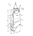
以下、図1〜4を参照して、光受信器1について説明する。光受信器1は、光受信器1の外側の輪郭を形成するハウジング2を有する。ハウジング2の形状およびサイズは、その応用例に依存する。図示の例では、ハウジング2の形状は、略方形である。ハウジング2の高さhは、たとえば、20mm〜500mm;または50mm〜300mm、または100mm〜200mmの範囲内とすることができる。ハウジング2の長さlは、たとえば、5mm〜300mm;または10mm〜200mm;または30mm〜100mm;または40mm〜75mmの範囲内とすることができる。ハウジング2の幅wは、たとえば、5mm〜200mm;または10mm〜100mm;または20mm〜75mm;または30mm〜60mmの範囲内とすることができる。高さh、長さl、および幅wは、応用例に応じて拡大および縮小することができる。ハウジング2は、典型的には、プラスチック材料または金属から作られる。
Hereinafter, the optical receiver 1 will be described with reference to FIGS. The optical receiver 1 has a
ハウジング2は、側壁3と、側壁3の円周の周りに配置された周壁4とを含む。側壁3および周壁4は、単一の部品、または互いに取り付けられた2つの別個の部品とすることができ、したがって2つの壁3、4は互いに一体化される。図示の例では、側壁3は、実質上平面であり、周壁4は、側壁3に直交して延びる。ハウジング2は、側壁3の反対側に配置された蓋5をさらに含む。蓋5は、ねじ6によって周壁4に取り付けられる。当然ながら、蓋5は、何らかの他の方法で、たとえば周壁4にスナップロックされることによって、周壁4に取り付けることができる。
The
ハウジング2には、ねじなどによって光受信器1を枠または何らかの他のタイプの外部構造に取り付けるために、孔15の形で位置決め手段が設けられる。さらに、ハウジング2は、光透過性部分(light−transmissive portion)7を有し、光ビームは、光透過性部分を通ってハウジング2の外側から内側へ進むことができる。光透過性部分7は、周壁4内に配置された光透過性材料の円形の部品である。他の例では、光透過性部分7は、側壁3または蓋5の中など、別の場所に配置することができ、光透過性部分7の形状は、異なることができ、たとえば方形とすることができる。また、光透過性部分7は、たとえばガラスもしくはプラスチックから作ることができ、または単にハウジング2内の開口部とすることができる。
The
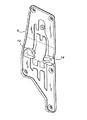
ハウジング2内には、反射器8およびレンズ9が配置される。反射器8は、光透過性部分7を通ってハウジング2に入った光ビームをレンズ9の方へ向け直すように配置される。レンズ9は、向け直された光ビームを焦点面へ透過させるように適用される。レンズ9は、光軸Oを画成する。レンズ9は凸レンズであるが、適した方法で光を屈折させる任意のレンズを使用することもできる。図示の例では、反射器8は、光軸Oに対してほぼ45°の角度で配置された平面鏡である。他の実施形態では、反射器8と光軸Oとの間の角度は、35°〜55°の範囲内とすることもできることに留意されたい。さらに、反射器8は、好ましくは、光がレンズ9の光軸Oに沿って反射されるように配置され、これは、光透過性部分7およびレンズ9の他の相対的な位置によって実現することもできる。場合により、いくつかの実施形態では、たとえば光透過性部分7および光軸Oが位置合わせされるとき、反射器8を必要としない。
A reflector 8 and a lens 9 are arranged in the
ホルダ10が、レンズ9を支持する。ホルダ10は、反射器8に近位の第1の部分と、反射器8に遠位の第2の部分とを有する。第1の部分は、レンズ9が取り付けられる孔を有する。第2の部分は、アーチ状の形状を有し、アーチの頂部部分の中央は、光軸Oとほぼ一直線に並んでいる。
The
ホルダ10は回転可能であり、光受信器1は第1および第2の調整手段11、12を有し、第1および第2の調整手段11、12の使用によって、ホルダ10を回転させることが可能である。図示の例では、第1および第2の調整手段11、12の各々はねじである。使用することができる他のタイプの第1および第2の調整手段11、12は、たとえば、ロック作用、たとえば摩擦に基づくプッシュプル式またはスナップフック式のロックによる円筒形のピンである。第1の調整手段11は、第1の軸A1の周りでホルダ10を回転させるように適用され、第2の調整手段12は、第1の軸A1に直交する第2の軸A2の周りでホルダ10を回転させるように適用される。図示の例では、第1および第2の軸A1、A2は、図2に示すデカルト座標系のz軸に直交する水平面内に位置する。第1の軸A1は、x軸に平行であり、第2の軸A2は、y軸に平行である。第1および第2の軸A1、A2は、ホルダ10が基準位置に配置されたとき、レンズ9の中心またはレンズ9のほぼ中心で互いに交差する。ホルダ10の基準位置は、光軸Oが第1および第2の軸A1、A2に直交するようなホルダ10の位置である。別の言い方をすると、ホルダ10が基準位置にあるとき、光軸Oはz軸に平行である。
The
図示の例では、第1の調整手段/ねじ11は、第2の軸A2に平行に配置され、第2の調整手段/ねじ12は、第1の軸A1に平行に配置される。第1および第2の調整手段11、12は、ホルダ10がその基準位置にあるとき、光軸Oに沿って第1および第2の軸A1、A2の平面から距離dをあけて同じ平面内に配置される。距離dは、応用例に依存するが、典型的には、35mm〜40mmの範囲、たとえば38mmである。異なる例では、第1および第2の調整手段11、12は、第1および第2の軸A1、A2の平面から異なる距離をあけて配置することができることに留意されたい。これは、第1および第2の調整手段11、12が同じ平面内に配置されないことを意味するはずである。
In the illustrated example, the first adjusting means / the
第1の調整手段11は、ホルダ10を第1の軸A1の周りで第1の向きから第2の向きへ回転させるために使用することができ、第2の調整手段12は、ホルダ10を第2の軸A2の周りで第3の向きから第4の向きへ回転させるために使用することができる。第1、第2、第3、および第4の向きは、レンズ9/ホルダ10の調整範囲の終点に対応することができる。ホルダ10は、第1の軸A1の周りで第1の向きと第2の向きとの間の第5の向き、および第2の軸A2の周りで第3の向きと第4の向きとの間の第6の向きに、ホルダ10を配置することによって、基準位置に位置することができる。第5の向きは、好ましくは、第1の向きと第2の向きとの間の実質上中間に配置される。第6の向きは、好ましくは、第3の向きと第4の向きとの間の実質上中間に配置される。
The first adjusting means 11 can be used to rotate the
ホルダ10の第1の部分の周りには、ばね作用部材13が円周方向に配置される。この例では、ばね作用部材13は、弾性部材であり、より正確にはゴムのOリングである。したがって、ばね作用部材13は、単一の連続する要素であるが、他の例では、ばね作用部材13は、いくつかの個別の要素によって形成することができる。Oリングは、円形の横断面を有する。Oリングの内径は、レンズ9のサイズに依存し、レンズ9のサイズは、応用例に依存するが、典型的には、25mm〜30mmの範囲内、たとえば28mmである。ばね作用部材13は、Oリングでなくてもよいことに留意されたい。他のばね作用部材13の例には、円形のリップおよびリブリングが含まれる。ばね作用部材13のさらなる例には、リングが含まれ、リングの横断面は、矩形などの方形、または長円形である。ばね作用部材13は、レンズホルダ10およびハウジング2がそれに応じて作製される限り、任意の断面を有することができる。さらに、Oリングは、切抜き、たとえば円形または方形の切抜きを有するゴム、プラスチック、またはさらには薄い金属の部品によって交換することもできる。このとき、円形の切抜きは、Oリングと同じ目的を果たすはずであり、この材料シートの剛性/可撓性が、ばね力を提供するはずである。
Around the first portion of the
ばね作用部材13は、台座14によって支持される。この例では、台座14は、ハウジング2内に溝によって形成される。溝は、ばね作用部材13とは逆の幾何形状を有する限り、任意の幾何形状を有することができる。ばね作用部材13および溝は、好ましくは、ともに嵌るはずである。図示の例では合計4つの溝が存在するが、当然ながら別の例では、この数は異なるものとすることができる。台座14の形状は、ばね作用部材13の形状に対して相補型であり、その結果、ばね作用部材13は台座14内に確実に嵌る。具体的には、溝は、ばね作用部材13、すなわちOリングの横断プロファイルに対して負または逆の半円形の横断プロファイルを有する。
The
場合により、溝は、ホルダ10が基準位置にあるとき、光軸Oに対して傾斜している平面内に配置することができる。別の言い方をすると、溝は、図2のデカルト座標系のz軸に直交しない平面内に配置することができる。より正確には、溝は、x軸およびy軸の周りで回転させた平面内に配置することができる。このように溝を配置することによって、調整範囲全体にわたってばね作用部材/Oリング13がねじ11、12からの力とは逆方向の力をホルダ10に及ぼすことが可能になる。それによって、逆方向に配置された2つのねじの代わりに、軸A1、A2の各々に対して1つのねじのみを使用して、ホルダ10を第1および第2の軸A1、A2の各々の周りで時計回りと反時計回りの両方に回転させることができる。ねじをホルダ10の方へ動かすと、ねじがホルダ10を押すため、ホルダ10が回転する。同じねじをホルダ10から離れる方へ動かすと、ばね作用部材13は後退するねじに追従するようにホルダ10を押すため、ホルダ10が(逆方向に)回転する。
In some cases, the groove can be arranged in a plane inclined with respect to the optical axis O when the
図1および図2に示す例では、光受信器1は:第1のねじ11をホルダ10の方へ動かすと、ホルダ10が正のx方向に見て反時計回りに回転し、第1のねじ11をホルダ10から離れる方へ動かすと、ホルダ10が正のx方向に見て時計回りに回転し、第2のねじ12をホルダ10の方へ動かすと、ホルダ10が正のy方向に見て時計回りに回転し、第2のねじ12をホルダ10から離れる方へ動かすと、ホルダ10が正のy方向に見て反時計回りに回転するように適用される。
In the example shown in FIGS. 1 and 2, the optical receiver 1: When the
図示の例では、溝の平面は、x軸およびy軸の周りで同じ角度だけ回転させられるが、他の例では、この通りであってもなくてもよい。回転角度は、たとえば、5°、3°、または2°など、7°以下とすることができる。一例として、x軸の周りのレンズ9/ホルダ10の調整範囲がz軸に対して−3°〜+3°であることが望ましい場合を考慮されたい。このとき、x軸の周りの平面の回転角度は、典型的には、3°になるように選択される。ホルダ10の第1の向きは、光軸Oがz軸に対して−3°の角度をなすことに対応することができ、ホルダ10の第2の向きは、光軸Oがz軸に対して+3°の角度をなすことに対応することができ、または逆も同様である。
In the example shown, the plane of the groove is rotated by the same angle around the x and y axes, but in other examples this may or may not be the case. The rotation angle can be 7 ° or less, such as 5 °, 3 °, or 2 °, for example. As an example, consider the case where it is desirable that the adjustment range of the lens 9 /
光受信器1は、焦点面に一致またはほぼ一致する受光領域16をさらに含む。受光領域16は、レンズ9に面する。第1の調整手段11、第2の調整手段12、および受光領域16は、光軸Oに沿って見るとレンズ9の同じ側に配置される。図示の例では、受光領域16は、ホルダ10の第2の部分の頂部に配置される。受光領域16は、ホルダ10に取り付けられた光検出器の一部を形成することができる。別法として、受光領域16は、光ビームが通過することができる表面とすることができ、次いで光ビームは、たとえばホルダ10内の孔の中に部分的に配置された光ファイバを介して、光受信器1の外側に配置されたセンサへ進むことができる。したがって、センサおよび光受信器1は、別個のユニットを形成することができる。
The optical receiver 1 further includes a
ホルダ10が基準位置にあるとき、光軸Oに沿ってレンズ9と第1および第2の調整手段A1、A2との間の距離は、レンズ9と受光領域16との間の距離の少なくとも50%、別法として少なくとも70%、少なくとも80%、少なくとも90%、または少なくとも100%とすることができる。追加または別法として、ホルダ10が基準位置にあるとき、光軸Oに沿ってレンズ9と第1および第2の調整手段A1、A2との間の距離は、150%以下、130%以下、120%以下、110%以下、または105%以下とすることができる。
When the
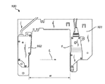
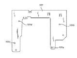
光学系100について、図5および図6を参照して次に説明する。光学系100は、図1〜4を参照して説明した光受信器1を装備する。光受信器1は、枠101上に取り付けられた自立型ユニットを形成する。枠101は、孔の形で位置決め手段101a、101b、101c、101dを有する。光受信器1は、ハウジング2内の孔15を通過して枠101内の孔に整合するねじによって、枠101に取り付けられる。自立型ユニットを形成する光放出器102が、光受信器1に対して空間的にロックされるように枠101に取り付けられる。光放出器102には、孔の形で位置決め手段が設けられる。光放出器102は、光放出器102の孔を通過して枠101内の孔に整合するねじによって、枠101に取り付けられる。
Next, the
光受信器1と光放出器102との間には間隙が存在する。間隙の幅Wは、特定用途向けの要件に依存するが、たとえば50mm〜300mm、または100mm〜250mm、または150mm〜200mmの範囲内とすることができる。光受信器1および光放出器102は、間隙の異なる側で互いに光学的に位置合わせされる。したがって、光受信器1は、光放出器102によって放出された光ビームを受けるように配置され、光受信器1の光透過性部分7は光放出器102に面する。光放出器102の光源は、典型的には、発光ダイオードまたはレーザダイオードである。光放出器102によって放出される光ビームの波長は、たとえば、400〜2000nm;または400nm〜700nm;または700〜2000nmの範囲内とすることができる。
There is a gap between the optical receiver 1 and the
使用の際には、光放出器102は、ほぼ幅Wの方向である放出方向に光ビームLを放出する。光ビームLは、光透過性部分7を通って入り、反射器8によってレンズ9の方へ反射される。レンズ9は、光ビームLを受光領域16へ透過させる。受光領域16に当たる光は、たとえば、光ファイバ内へ結合することができ、光ファイバは、光を検出のためにセンサへ透過させる。
In use, the
典型的には、受光領域16上に入る光を可能な限り多くしたいと考える。レンズ9の向きならびに光ビームLの方向および/または位置が整合しておらず、その結果、光のすべてまたは一部が受光領域16に当たっていない場合、より多くの光が受光領域16上に入るようにレンズ9の向きを調整することができる。レンズ9はホルダ10とともに動き、したがって、第1および第2の調整手段11、12を使用してホルダ10を回転させることによって、レンズ9の向きを調整することができる。
Typically, it is desired to increase the amount of light entering the
光学系100は、たとえば、光受信器1と光放出器102との間の間隙を通って光放出器102の放出方向に実質上直交する方向に使用済み飲料ボトルを輸送するコンベアを有する自動回収機(reverse vending machine)の一部とすることができる。光受信器1は、間隙内に存在する食品または飲料容器を透過した光を受け、それにより、たとえば間隙内にボトルが存在するか否かを判定し、またボトルの異なる特性も判定することが可能になる。判定することができる他の特性の例には、プラスチック材料のタイプ、およびボトルまたは食品トレーなどの空の食品容器の色がある。たとえばプラスチックでない半透明の物体が存在することを識別することによって、ガラスを識別することもできる。
The
本考案は上記の実施形態に一切限定されないことが、当業者には理解される。逆に、添付の特許請求の範囲の範囲内で、多くの修正形態および変形形態が可能である。たとえば、光学系100は、分類、収集、および/または識別に使用される装置内などで物体の色、材料、または他の特性を識別することに関心があるとき、自動回収機以外の他のタイプの装置にも適している。追加として、開示する実施形態に対する変形形態は、クレームされる本考案を実施する際、図面、開示、および添付の特許請求の範囲を検討することによって、当業者には理解および実行することができる。特許請求の範囲では、「含む(comprising)」という単語は、他の要素または工程を除外するものではなく、不定冠詞「a」または「an」は複数を除外するものではない。
It will be understood by those skilled in the art that the present invention is not limited to the above-described embodiments. On the contrary, many modifications and variations are possible within the scope of the appended claims. For example, when the
1 光受信器
2 ハウジング
3 側壁
4 周壁
5 蓋
6 ねじ
7 光透過性部分
8 反射器
9 レンズ
10 ホルダ
11 第1の調整手段、第1のねじ
12 第2の調整手段、第2のねじ
13 ばね作用部材、Oリング
14 台座
15 孔
16 受光領域
100 光学系
101 枠
101a 位置決め手段
101b 位置決め手段
101c 位置決め手段
101d 位置決め手段
102 光放出器
d 距離
h 高さ
l 長さ
w 幅
A1 第1の軸
A2 第2の軸
L 光ビーム
O 光軸
W 幅
DESCRIPTION OF SYMBOLS 1
Claims (13)
台座(14)を有するハウジング(2)と;
該ハウジング(2)内に配置されたレンズ(9)であって、光軸(O)および焦点面を画成するレンズ(9)と;
該レンズ(9)の該焦点面に配置され、該レンズ(9)を透過した光ビームを受けるように配置された受光領域(16)と;
第1の軸(A1)および該第1の軸(A1)に直交する第2の軸(A2)の周りで回転可能なホルダ(10)であって、該ホルダ(10)が基準位置に配置されたとき、第1および第2の軸(A1、A2)がレンズ(9)の光軸(O)に直交しかつ該レンズ(9)の中心で互いに交差し、該ホルダ(10)が、レンズ(9)がホルダ(10)の回転に追従するように該レンズ(9)を支持する、ホルダと;
該ホルダ(10)を第1の軸(A1)の周りで第1の向きから第2の向きへ回転させる第1の調整手段(11)、および該ホルダ(10)を第2の軸(A2)の周りで第3の向きから第4の向きへ回転させる第2の調整手段(12)であって、第1の調整手段(11)、第2の調整手段(12)、および受光領域(16)が、光軸(O)に沿って見るとレンズ(9)の同じ側に配置される、第1の調整手段および第2の調整手段と;
ホルダ(10)の円周の周りでハウジング(2)の台座(14)内に配置されたばね作用部材(13)であって、ホルダ(10)が第1および第2の軸(A1、A2)の周りで回転するときに圧縮され、それによってホルダ(10)に力を及ぼし、ホルダ(10)を第1および第3の向きの方へ回転させようとするように適用されたばね作用部材(13)とを含む前記光受信器。 An optical receiver (1):
A housing (2) having a pedestal (14);
A lens (9) disposed within the housing (2), the lens (9) defining an optical axis (O) and a focal plane;
A light receiving region (16) disposed at the focal plane of the lens (9) and disposed to receive a light beam transmitted through the lens (9);
A first axis (A 1) and rotatable holder about a second axis orthogonal to said first axis (A 1) (A 2) (10), the holder (10) is a reference When placed in position, the first and second axes (A 1 , A 2 ) are perpendicular to the optical axis (O) of the lens (9) and intersect each other at the center of the lens (9), and the holder A holder that supports the lens (9) such that the lens (9) follows the rotation of the holder (10);
First adjusting means (11) for rotating the holder (10) around the first axis (A 1 ) from the first direction to the second direction, and the holder (10) with the second axis ( A second adjusting means (12) that rotates from the third direction to the fourth direction around A 2 ), the first adjusting means (11), the second adjusting means (12), and the light receiving First and second adjustment means, wherein the region (16) is arranged on the same side of the lens (9) when viewed along the optical axis (O);
A spring acting member (13) disposed in the pedestal (14) of the housing (2) around the circumference of the holder (10), wherein the holder (10) is connected to the first and second shafts (A 1 , A 2 ) a spring acting member adapted to compress when rotating about, thereby exerting a force on the holder (10) and to attempt to rotate the holder (10) in the first and third orientations The optical receiver comprising (13).
請求項1〜10のいずれか1項に記載の光受信器(1)を含む自立型ユニットと、
光受信器(1)へ光ビームを放出するように配置された光放出器(102)を含む自立型ユニットと、
互いに光学的に位置合わせされるように該自立型ユニットを取り付け可能な枠(101)とを含み、
ここで、該枠(101)ならびに該第1および第2の自立型ユニットは、該自立型ユニットを互いに対して空間的にロックする相互整合式位置決め手段を含む、前記光学系。 An optical system (100) comprising:
A self-supporting unit comprising the optical receiver (1) according to any one of claims 1 to 10;
A free-standing unit comprising a light emitter (102) arranged to emit a light beam to a light receiver (1);
A frame (101) to which the freestanding unit can be mounted so as to be optically aligned with each other;
Wherein the frame (101) and the first and second freestanding units comprise mutual alignment positioning means for spatially locking the freestanding units relative to each other.
請求項11または12に記載のシステムと、
輸送手段とを含み、該輸送手段は、前記使用済み飲料または食品容器が、光放出器を含む前記自立型ユニットと光受信器を含む前記自立型ユニットとの間を通ることを可能にし、光放出器を含む前記自立型ユニットから放出された光によって照射されるように構成され、該放出された光は、光受信器を含む前記自立型ユニットによって少なくとも部分的に受光される、前記自動回収機。 Automatic collection machine for handling used beverage or food containers:
A system according to claim 11 or 12,
Means for allowing said used beverage or food container to pass between said free-standing unit comprising a light emitter and said free-standing unit comprising a light receiver; The automatic collection configured to be illuminated by light emitted from the freestanding unit including an emitter, the emitted light being at least partially received by the freestanding unit including an optical receiver; Machine.
Applications Claiming Priority (2)
| Application Number | Priority Date | Filing Date | Title |
|---|---|---|---|
| CN201620768826.7 | 2016-07-19 | ||
| CN201620768826.7U CN206178201U (en) | 2016-07-19 | 2016-07-19 | Optical receiver, and relevant photosystem and waste recovery machine |
Publications (1)
| Publication Number | Publication Date |
|---|---|
| JP3207976U true JP3207976U (en) | 2016-12-15 |
Family
ID=57544032
Family Applications (1)
| Application Number | Title | Priority Date | Filing Date |
|---|---|---|---|
| JP2016004684U Active JP3207976U (en) | 2016-07-19 | 2016-09-27 | OPTICAL RECEIVER HAVING LENS ADJUSTMENT ARRANGEMENT |
Country Status (2)
| Country | Link |
|---|---|
| JP (1) | JP3207976U (en) |
| CN (1) | CN206178201U (en) |
-
2016
- 2016-07-19 CN CN201620768826.7U patent/CN206178201U/en active Active
- 2016-09-27 JP JP2016004684U patent/JP3207976U/en active Active
Also Published As
| Publication number | Publication date |
|---|---|
| CN206178201U (en) | 2017-05-17 |
Similar Documents
| Publication | Publication Date | Title |
|---|---|---|
| JP5915222B2 (en) | Inner diameter measuring device | |
| US10816665B2 (en) | Surveying system | |
| US9612109B2 (en) | Inner diameter measuring device | |
| US7562999B2 (en) | Operating lamp with adjustable light sources capable of generating a light field of a Gaussian distribution | |
| US7679844B2 (en) | Lens holder | |
| US11656435B2 (en) | Imaging lens and camera module | |
| US7424184B2 (en) | Optical member and optical communication module with easy height adjustment | |
| KR20030081118A (en) | Anti-thief security sensor assembly | |
| JP3207976U (en) | OPTICAL RECEIVER HAVING LENS ADJUSTMENT ARRANGEMENT | |
| JP4019995B2 (en) | Line indicator | |
| US7572021B2 (en) | LED unit with annular mounting structure and mounting method thereof | |
| US10146047B1 (en) | Optical base station | |
| JP2001264453A (en) | Optical device | |
| US20030156409A1 (en) | Variable incidence oblique illuminator device | |
| US5724181A (en) | Sight scope | |
| JP2019021602A (en) | Lens unit and vehicular lighting fixture | |
| JP2011085655A (en) | Mirau type interference objective lens and microscope | |
| US10725262B2 (en) | Lens holding mechanism and optical emitter | |
| CN110726092A (en) | Annular light source device | |
| US11029510B2 (en) | Optical module | |
| CN214375602U (en) | Frame member for aligning optical axis and laser focusing instrument | |
| US10557975B2 (en) | Reflecting mirror and mirror holding mechanism | |
| CN110927916A (en) | Adjusting device for rear intercept of lens and camera | |
| JP2020190495A (en) | Distance measurement device | |
| JP2006048937A (en) | Mounting structure of multiple-optical-axis photoelectric sensor, mounting method, and mounting fixture used for it |
Legal Events
| Date | Code | Title | Description |
|---|---|---|---|
| A521 | Request for written amendment filed |
Free format text: JAPANESE INTERMEDIATE CODE: A523 Effective date: 20161111 |
|
| R150 | Certificate of patent or registration of utility model |
Ref document number: 3207976 Country of ref document: JP Free format text: JAPANESE INTERMEDIATE CODE: R150 |
|
| R250 | Receipt of annual fees |
Free format text: JAPANESE INTERMEDIATE CODE: R250 |
|
| R250 | Receipt of annual fees |
Free format text: JAPANESE INTERMEDIATE CODE: R250 |
|
| R250 | Receipt of annual fees |
Free format text: JAPANESE INTERMEDIATE CODE: R250 |
|
| R250 | Receipt of annual fees |
Free format text: JAPANESE INTERMEDIATE CODE: R250 |
|
| R250 | Receipt of annual fees |
Free format text: JAPANESE INTERMEDIATE CODE: R250 |