JP3205938U - Systems that use consumables in consumables and hot wire systems - Google Patents
Systems that use consumables in consumables and hot wire systems Download PDFInfo
- Publication number
- JP3205938U JP3205938U JP2015600148U JP2015600148U JP3205938U JP 3205938 U JP3205938 U JP 3205938U JP 2015600148 U JP2015600148 U JP 2015600148U JP 2015600148 U JP2015600148 U JP 2015600148U JP 3205938 U JP3205938 U JP 3205938U
- Authority
- JP
- Japan
- Prior art keywords
- substrate
- consumable
- range
- metal core
- wire
- Prior art date
- Legal status (The legal status is an assumption and is not a legal conclusion. Google has not performed a legal analysis and makes no representation as to the accuracy of the status listed.)
- Expired - Fee Related
Links
Images


Classifications
-
- B—PERFORMING OPERATIONS; TRANSPORTING
- B23—MACHINE TOOLS; METAL-WORKING NOT OTHERWISE PROVIDED FOR
- B23K—SOLDERING OR UNSOLDERING; WELDING; CLADDING OR PLATING BY SOLDERING OR WELDING; CUTTING BY APPLYING HEAT LOCALLY, e.g. FLAME CUTTING; WORKING BY LASER BEAM
- B23K35/00—Rods, electrodes, materials, or media, for use in soldering, welding, or cutting
- B23K35/02—Rods, electrodes, materials, or media, for use in soldering, welding, or cutting characterised by mechanical features, e.g. shape
- B23K35/0255—Rods, electrodes, materials, or media, for use in soldering, welding, or cutting characterised by mechanical features, e.g. shape for use in welding
- B23K35/0261—Rods, electrodes, wires
-
- B—PERFORMING OPERATIONS; TRANSPORTING
- B23—MACHINE TOOLS; METAL-WORKING NOT OTHERWISE PROVIDED FOR
- B23K—SOLDERING OR UNSOLDERING; WELDING; CLADDING OR PLATING BY SOLDERING OR WELDING; CUTTING BY APPLYING HEAT LOCALLY, e.g. FLAME CUTTING; WORKING BY LASER BEAM
- B23K26/00—Working by laser beam, e.g. welding, cutting or boring
- B23K26/14—Working by laser beam, e.g. welding, cutting or boring using a fluid stream, e.g. a jet of gas, in conjunction with the laser beam; Nozzles therefor
- B23K26/1423—Working by laser beam, e.g. welding, cutting or boring using a fluid stream, e.g. a jet of gas, in conjunction with the laser beam; Nozzles therefor the flow carrying an electric current
-
- B—PERFORMING OPERATIONS; TRANSPORTING
- B23—MACHINE TOOLS; METAL-WORKING NOT OTHERWISE PROVIDED FOR
- B23K—SOLDERING OR UNSOLDERING; WELDING; CLADDING OR PLATING BY SOLDERING OR WELDING; CUTTING BY APPLYING HEAT LOCALLY, e.g. FLAME CUTTING; WORKING BY LASER BEAM
- B23K26/00—Working by laser beam, e.g. welding, cutting or boring
- B23K26/20—Bonding
- B23K26/21—Bonding by welding
- B23K26/211—Bonding by welding with interposition of special material to facilitate connection of the parts
-
- B—PERFORMING OPERATIONS; TRANSPORTING
- B23—MACHINE TOOLS; METAL-WORKING NOT OTHERWISE PROVIDED FOR
- B23K—SOLDERING OR UNSOLDERING; WELDING; CLADDING OR PLATING BY SOLDERING OR WELDING; CUTTING BY APPLYING HEAT LOCALLY, e.g. FLAME CUTTING; WORKING BY LASER BEAM
- B23K35/00—Rods, electrodes, materials, or media, for use in soldering, welding, or cutting
- B23K35/02—Rods, electrodes, materials, or media, for use in soldering, welding, or cutting characterised by mechanical features, e.g. shape
- B23K35/0222—Rods, electrodes, materials, or media, for use in soldering, welding, or cutting characterised by mechanical features, e.g. shape for use in soldering, brazing
- B23K35/0227—Rods, wires
-
- B—PERFORMING OPERATIONS; TRANSPORTING
- B23—MACHINE TOOLS; METAL-WORKING NOT OTHERWISE PROVIDED FOR
- B23K—SOLDERING OR UNSOLDERING; WELDING; CLADDING OR PLATING BY SOLDERING OR WELDING; CUTTING BY APPLYING HEAT LOCALLY, e.g. FLAME CUTTING; WORKING BY LASER BEAM
- B23K35/00—Rods, electrodes, materials, or media, for use in soldering, welding, or cutting
- B23K35/02—Rods, electrodes, materials, or media, for use in soldering, welding, or cutting characterised by mechanical features, e.g. shape
- B23K35/0222—Rods, electrodes, materials, or media, for use in soldering, welding, or cutting characterised by mechanical features, e.g. shape for use in soldering, brazing
- B23K35/0244—Powders, particles or spheres; Preforms made therefrom
- B23K35/025—Pastes, creams, slurries
-
- B—PERFORMING OPERATIONS; TRANSPORTING
- B23—MACHINE TOOLS; METAL-WORKING NOT OTHERWISE PROVIDED FOR
- B23K—SOLDERING OR UNSOLDERING; WELDING; CLADDING OR PLATING BY SOLDERING OR WELDING; CUTTING BY APPLYING HEAT LOCALLY, e.g. FLAME CUTTING; WORKING BY LASER BEAM
- B23K35/00—Rods, electrodes, materials, or media, for use in soldering, welding, or cutting
- B23K35/02—Rods, electrodes, materials, or media, for use in soldering, welding, or cutting characterised by mechanical features, e.g. shape
- B23K35/0255—Rods, electrodes, materials, or media, for use in soldering, welding, or cutting characterised by mechanical features, e.g. shape for use in welding
- B23K35/0261—Rods, electrodes, wires
- B23K35/0277—Rods, electrodes, wires of non-circular cross-section
-
- B—PERFORMING OPERATIONS; TRANSPORTING
- B23—MACHINE TOOLS; METAL-WORKING NOT OTHERWISE PROVIDED FOR
- B23K—SOLDERING OR UNSOLDERING; WELDING; CLADDING OR PLATING BY SOLDERING OR WELDING; CUTTING BY APPLYING HEAT LOCALLY, e.g. FLAME CUTTING; WORKING BY LASER BEAM
- B23K35/00—Rods, electrodes, materials, or media, for use in soldering, welding, or cutting
- B23K35/22—Rods, electrodes, materials, or media, for use in soldering, welding, or cutting characterised by the composition or nature of the material
- B23K35/24—Selection of soldering or welding materials proper
- B23K35/32—Selection of soldering or welding materials proper with the principal constituent melting at more than 1550 degrees C
- B23K35/327—Selection of soldering or welding materials proper with the principal constituent melting at more than 1550 degrees C comprising refractory compounds, e.g. carbides
-
- B—PERFORMING OPERATIONS; TRANSPORTING
- B23—MACHINE TOOLS; METAL-WORKING NOT OTHERWISE PROVIDED FOR
- B23K—SOLDERING OR UNSOLDERING; WELDING; CLADDING OR PLATING BY SOLDERING OR WELDING; CUTTING BY APPLYING HEAT LOCALLY, e.g. FLAME CUTTING; WORKING BY LASER BEAM
- B23K35/00—Rods, electrodes, materials, or media, for use in soldering, welding, or cutting
- B23K35/22—Rods, electrodes, materials, or media, for use in soldering, welding, or cutting characterised by the composition or nature of the material
- B23K35/36—Selection of non-metallic compositions, e.g. coatings, fluxes; Selection of soldering or welding materials, conjoint with selection of non-metallic compositions, both selections being of interest
- B23K35/3612—Selection of non-metallic compositions, e.g. coatings, fluxes; Selection of soldering or welding materials, conjoint with selection of non-metallic compositions, both selections being of interest with organic compounds as principal constituents
- B23K35/3613—Polymers, e.g. resins
-
- B—PERFORMING OPERATIONS; TRANSPORTING
- B23—MACHINE TOOLS; METAL-WORKING NOT OTHERWISE PROVIDED FOR
- B23K—SOLDERING OR UNSOLDERING; WELDING; CLADDING OR PLATING BY SOLDERING OR WELDING; CUTTING BY APPLYING HEAT LOCALLY, e.g. FLAME CUTTING; WORKING BY LASER BEAM
- B23K35/00—Rods, electrodes, materials, or media, for use in soldering, welding, or cutting
- B23K35/40—Making wire or rods for soldering or welding
-
- B—PERFORMING OPERATIONS; TRANSPORTING
- B23—MACHINE TOOLS; METAL-WORKING NOT OTHERWISE PROVIDED FOR
- B23K—SOLDERING OR UNSOLDERING; WELDING; CLADDING OR PLATING BY SOLDERING OR WELDING; CUTTING BY APPLYING HEAT LOCALLY, e.g. FLAME CUTTING; WORKING BY LASER BEAM
- B23K9/00—Arc welding or cutting
- B23K9/10—Other electric circuits therefor; Protective circuits; Remote controls
- B23K9/1093—Consumable electrode or filler wire preheat circuits
Landscapes
- Engineering & Computer Science (AREA)
- Mechanical Engineering (AREA)
- Physics & Mathematics (AREA)
- Optics & Photonics (AREA)
- Plasma & Fusion (AREA)
- Arc Welding In General (AREA)
- Polishing Bodies And Polishing Tools (AREA)
Abstract
【課題】パッドルを創り出す強力エネルギ源と、その融解温度又はその融解温度付近まで加熱され且つ溶接パッドル上に溶着されるホットワイヤ溶接プロセスのための消耗品を提供する。【解決手段】溶接ワイヤであって、外表面を有する中実な金属コアと、金属コアの外表面に溶着される基質とを含み、基質は、結合剤と、粒子とを含む。結合剤は、有機結合剤又は重合結合剤のいずれかであり、粒子は導電性であり、0.05mm〜0.5mmの範囲内の、0.125mm〜0.3mmの範囲内の、又は0.3mm〜0.5mmの範囲内の公称直径を有する。【選択図】図1A high energy source for creating a puddle and a consumable for a hot wire welding process that is heated to or near its melting temperature and deposited on a weld puddle. A welding wire includes a solid metal core having an outer surface and a substrate welded to the outer surface of the metal core, the substrate including a binder and particles. The binder is either an organic binder or a polymeric binder and the particles are electrically conductive and in the range of 0.05 mm to 0.5 mm, in the range of 0.125 mm to 0.3 mm, or 0. Have a nominal diameter in the range of 3 mm to 0.5 mm. [Selection] Figure 1
Description
特定の実施態様は、コンシューマブルと、接合、オーバーレイ(overlay)及びクラッディング作業においてコンシューマブルを用いる方法及びシステムとに関する。より具体的には、特定の実施態様は、特別な構成を有するコンシューマブルと、鑞接、クラッディング、肉盛(building-up)、充填(filling)、表面硬化オーバーレイ(hard-facing overlay)、接合及び溶接用途のいずれかのためにホットワイヤシステムにおいてそれらを用いる方法及びシステムとに関する。 Particular embodiments relate to consumables and methods and systems that use consumables in splicing, overlay, and cladding operations. More specifically, certain embodiments include consumables having a special configuration, as well as welding, cladding, building-up, filling, hard-facing overlay, It relates to methods and systems for using them in hot wire systems for either joining and welding applications.
(関連出願の参照)
本考案は2012年7月12日に出願された米国特許出願第13/547,649号に記載される改良方法及びシステムに関し、その全文をここに参照として援用する。
(Refer to related applications)
The present invention relates to an improved method and system described in US patent application Ser. No. 13 / 547,649, filed Jul. 12, 2012, which is hereby incorporated by reference in its entirety.
多くの場合には、所望の化学的性質又は物理的特性を達成するために溶接又はオーバーレイプロセスにおいて特別な材料を用いることが望ましい。しかしながら、材料は分解したり酸化したり等するので、時には、(従来的なアーク溶接又はアークオーバーレイ作業においては)高温アークを通じて十分に移行しない材料を用いることが望ましい。更に、時には、適切な粒子サイズ及び密度において所望の材料を利用するコンシューマブルを創り出すことは困難であり得る。従って、所与の溶接又はオーバーレイ作業において所望の材料及び粒子サイズを与える柔軟性を備えるコンシューマブルを有することが望ましい。 In many cases, it is desirable to use special materials in the welding or overlay process to achieve the desired chemical or physical properties. However, it is sometimes desirable to use materials that do not migrate well through high temperature arcs (in conventional arc welding or arc overlay operations) because the materials decompose, oxidize, and the like. Further, sometimes it can be difficult to create a consumable that utilizes the desired material at the appropriate particle size and density. Therefore, it is desirable to have a consumable with the flexibility to give the desired material and particle size in a given welding or overlay operation.
従来的なアプローチ、伝統的なアプローチ、及び提案のアプローチの更なる制約及び不利点は、図面を参照して本明細書の残余に示す本考案の実施態様とのそのようなアプローチの比較を通じて、当業者に明らかになるであろう。 Further limitations and disadvantages of the traditional approach, traditional approach, and proposed approach will be discussed through comparison of such approaches with embodiments of the present invention shown in the remainder of this specification with reference to the drawings. It will be apparent to those skilled in the art.
この考案は、請求項1に従ったコンシューマブルによって、上述の制約及び不利点を少なくとも部分的に取り除く。従属項から好適実施態様を引き出してもよい。更に、請求項1のコンシューマブル内に含められる導電性粒子は、基質が、基質が導電性であることを可能にする粒子密度を有するよう、基質を通じて分配されるならば、好ましいことがある。本考案の実施態様は、少なくとも1つの強力エネルギ源を用いて溶融パッドルを創り出し、アークが起こるときを検出し或いは上方閾値を決定してワイヤとパッドルとの間にアークが形成されるのを防止するための、システム及び方法を含む。コアとコアの外表面に付着させられる溶接基質とを有する溶接ワイヤが溶融パッドルに向けられ、溶接基質及びコアの両方が導電性である。溶接ワイヤは、溶接ワイヤが溶融パッドルと接触するときに、溶接ワイヤがパッドル内で溶解するような温度まで、電源からの溶接ワイヤ加熱信号で加熱される。溶接ワイヤの溶着中、溶接ワイヤと溶融パッドルとの間で接触が維持され、プロセス中、溶接ワイヤとパッドルとの間にアークが生成されないよう、溶接ワイヤ加熱信号が上方閾値に達するときに、溶接ワイヤ加熱信号が停止される(或いはアーク放電を防止するよう変更される)ように、溶接ワイヤ加熱信号からのフィードバックが監視される。次に、溶接ワイヤ加熱信号は元に戻されて、溶接ワイヤを加熱することを続ける。溶接基質は、溶融パッドル内に蒸着させられるべき導電性の粒子を有する。 The invention at least partially removes the above-mentioned limitations and disadvantages by a consumable according to claim 1. Preferred embodiments may be derived from the dependent claims. Furthermore, the conductive particles included within the consumable of claim 1 may be preferred if the substrate is distributed through the substrate to have a particle density that allows the substrate to be conductive. Embodiments of the present invention use at least one strong energy source to create a melt puddle and detect when an arc occurs or determine an upper threshold to prevent an arc from forming between the wire and the puddle. Systems and methods for doing so. A welding wire having a core and a welding substrate attached to the outer surface of the core is directed to the melt puddle, and both the welding substrate and the core are conductive. The welding wire is heated with a welding wire heating signal from the power source to a temperature such that when the welding wire contacts the molten puddle, the welding wire melts within the puddle. During welding of the welding wire, contact is maintained between the welding wire and the melted puddle, and welding is performed when the welding wire heating signal reaches the upper threshold so that no arc is generated between the welding wire and the puddle during the process. The feedback from the welding wire heating signal is monitored so that the wire heating signal is stopped (or modified to prevent arcing). The welding wire heating signal is then reinstated to continue heating the welding wire. The welding substrate has conductive particles to be deposited in the molten puddle.
請求される考案のこれらの及び他の構造(features)、並びにその例示の実施態様の詳細は、以下の記載及び図面からより十分に理解されるであろう。 These and other features of the claimed device, as well as details of exemplary embodiments thereof, will be more fully understood from the following description and drawings.
本考案の上記の及び/又は他の特徴(aspects)は、添付の図面を参照して本考案の例示的な実施態様を詳細に記載することによってより明らかになるであろう。 The above and / or other aspects of the present invention will become more apparent by describing in detail exemplary embodiments of the present invention with reference to the accompanying drawings.
「オーバーレイ」という用語は、ここでは広義において用いられ、鑞接、クラッディング、肉盛(building-up)、充填(filling)、及び表面硬化(hard-facing)を含む、あらゆる用途を指し得る。例えば、鑞接用途において、溶接金属は毛管作用を介して継手の緊密に適合する表面に分配される。それに対して、「鑞付け溶接」用途において、溶接金属は間隙内に流入させられる。しかしながら、ここで用いられるときには、両方の技法がオーバーレイ用途として広く言及される。 The term “overlay” is used herein in a broad sense and may refer to any application, including scuffing, cladding, building-up, filling, and hard-facing. For example, in brazing applications, the weld metal is distributed to the tightly fitting surface of the joint via capillary action. In contrast, in “brass welding” applications, the weld metal is allowed to flow into the gap. However, as used herein, both techniques are widely referred to as overlay applications.
図1は、鑞接、クラッディング、肉盛、充填、表面硬化オーバーレイ、及び接合/溶接用途のいずれかを行うための、溶接ワイヤフィーダ及びエネルギ源システム100の組み合わせの例示的な実施態様の機能的なブロック図である。システム100は、レーザビーム110をワークピース115の上に集中させてワークピースを加熱し得るレーザサブシステムを含む。レーザサブシステムは、強力エネルギ源である。レーザサブシステムは、二酸化炭素、Nd:YAG、Ybディスク、Ybファイバ、ファイバ伝送(fiber delivered)又はダイレクトダイオード(direct diode)レーザシステムを非限定的に含む、任意の種類の高エネルギレーザ源であり得る。更に、十分なエネルギを有するならば、白色光又は石英レーザ型のシステムも用い得る。システムの他の実施態様は、強力エネルギ源として働く電子ビーム、プラズマアーク溶接サブシステム、ガスタングステンアーク溶接サブシステム、ガスメタルアーク溶接サブシステム、有芯アーク溶接サブシステム、及びサブマージドアーク溶接サブシステムのうちの少なくとも1つを含んでよい。以下の明細書は、レーザシステム、ビーム及び電源に繰返し言及するが、如何なる強力エネルギ源をも用い得るので、この言及は例示的であることが理解されなければならない。例えば、強力エネルギ源は、少なくとも500W/cm2をもたらし得る。レーザサブシステムは、互いに動作的に接続されるレーザ装置120及びレーザ電源130を含む。レーザ電源130はレーザ装置120を作動させる電力をもたらす。
FIG. 1 illustrates the function of an exemplary embodiment of a combination of a welding wire feeder and
システム100は、レーザビーム110の近傍においてワークピース115と接触する少なくとも1つの抵抗溶接ワイヤ140も含む。もちろん、ここにおいてワークピース115への言及により、溶融パッドルはワークピース115の部分と考えられ、よって、ワークピース115との接触への言及は、パッドルとの接触を含む。高温溶接ワイヤフィーダサブシステムは、溶接ワイヤフィーダ150と、コンタクトチューブ160と、ホットワイヤ電源170とを含む。動作中、レーザビーム110に先導する溶接ワイヤ140は、コンタクトチューブ160とワークピース115との間に動作的に接続されるホットワイヤ溶接電源170からの電流によって抵抗加熱される。本考案の実施態様によれば、ホットワイヤ溶接電源170は直流(DC)電源であるが、交流(AC)又は他の種類の電源も可能である。溶接ワイヤ140は、溶接ワイヤフィーダ150からコンタクトチューブ160を通じてワークピース115に送られ、コンタクトチューブ160を越えて延びる。溶接ワイヤ140の延長部分は、ワークピース上の溶接パッドルとの接触時又は接触前に延長部分が融点に接近するか或いは達するように抵抗加熱される。レーザビーム110は、ワークピース115のベース金属(基材)の一部を溶解させて、ワークピース115上に溶融パッドルを形成し且つワークピース115上で溶接ワイヤ140も溶解させる働きをする。電源170は、溶接ワイヤ140を抵抗加熱するのに必要とされるエネルギの大部分をもたらす。フィーダシステムは、本考案の特定の他の実施態様に従って、1つ又はそれよりも多くのワイヤを同時に提供し得てもよい。例えば、ワークピースを表面硬化し且つ/或いはワークピースに耐食性をもたらすために第1のワイヤを用い、ワークピースに構造(structure)を加えるために第2のワイヤを用いてよい。
システム100は、レーザビーム110及び抵抗溶接ワイヤ140が互いに対して一定の関係に留まるよう、レーザビーム110(エネルギ源)及び抵抗溶接ワイヤ140を(少なくとも相対的な意味において)ワークピース115に沿って同じ方向に動かし得る運動制御サブシステムを更に含む。様々な実施態様によれば、ワークピース115を実際に動かすことによって或いはレーザ装置120及びホットワイヤフィーダサブシステムを動かすことによって、ワークピース115とレーザ/ワイヤの組み合わせとの間の相対的な運動を達成し得る。図1において、運動制御サブシステムは、ロボット190に動作的に接続される運動コントローラ180を含む。運動コントローラ180は、ロボット190の動きを制御する。レーザビーム110及び溶接ワイヤ140がワークピース115に沿って効果的に進行するよう、ロボット190はワークピース115に動作的に接続されて(例えば、機械的に固定されて)、ワークピース115を方向125に動かす。本考案の代替的な実施態様によれば、レーザ装置120及びコンタクトチューブ160を単一のヘッドに統合してよい。ヘッドに動作的に接続される運動制御サブシステムを介して、ヘッドをワークピースに沿って移動させてよい。
The
一般的には、強力エネルギ源/ホットワイヤをワークピースに対して移動させる得る幾つかの方法がある。例えば、ワークピースが丸いならば、強力エネルギ源/ホットワイヤは静止的であり、ワークピースは強力エネルギ源/ホットワイヤの下で回転してよい。代替的に、ロボットアーム又は線形トラクタが丸いワークピースと平行に動き、ワークピースが回転させられると、強力エネルギ源/ホットワイヤは連続的に動き或いは一回転毎に割り出して、例えば、丸いワークピースの表面をオーバーレイしてよい。ワークピースが平坦であるか或いは少なくとも丸くないならば、図1に示すように、強力エネルギ源/ホットワイヤの下でワークピースを動かしてよい。しかしながら、ロボットアーム又は線形トラクタを用いて或いはビーム取り付けキャリッジさえも用いて、強力エネルギ源/ホットワイヤをワークピースに対して動かしてよい。 In general, there are several ways in which the strong energy source / hot wire can be moved relative to the workpiece. For example, if the workpiece is round, the high energy source / hot wire may be stationary and the workpiece may rotate under the high energy source / hot wire. Alternatively, when the robot arm or linear tractor moves in parallel with the round workpiece and the workpiece is rotated, the strong energy source / hot wire is continuously moved or indexed every revolution, eg, round workpiece You may overlay the surface. If the workpiece is flat or at least not round, the workpiece may be moved under a strong energy source / hot wire as shown in FIG. However, the high energy source / hot wire may be moved relative to the workpiece using a robot arm or linear tractor or even a beam mounting carriage.
システム100は、感知及び電流制御サブシステム195を更に含み、感知及び電流制御サブシステム195は、ワークピース115及びコンタクトチューブ160に動作的に接続され(即ち、ホットワイヤ電源170の出力に効果的に接続され)、ワークピース115とホットワイヤ140との間の電位差(即ち、電圧V)と、ワークピース及びホットワイヤ140を通じる電流(I)とを測定し得る。感知及び電流制御サブシステム195は、更に、測定される電圧及び電流から抵抗値(R=V/I)及び/又は電力値(P=V*I)を計算し得てもよい。一般的には、ホットワイヤ140がワークピース115と接触するとき、ホットワイヤ140とワークピース115との間の電位差はゼロボルトであるか或いはゼロボルトに極めて近い。結果的に、感知及び電流制御サブシステム195は、ここに参照としてその全文を援用する出願中により詳細に記載されるように、感知することに応答して抵抗溶接ワイヤ140を通じる電流の流れを更に制御し得るよう、抵抗溶接ワイヤ140がワークピース115と接触し且つホットワイヤ電源170と動作的に接続されるときを感知し得る。具体的には、加熱電流は、ワイヤ140とパッドルとの間にアークが生成されないように制御され、加熱電流は、アークが検出されるときに或いは閾値(電圧、電流及び/又は電力)に達するときに、アークが生成されないように加熱電流が停止されるか或いは変更されるように制御される。本考案の他の実施態様によれば、感知及び電流制御サブシステム195は、ホットワイヤ電源170の一体的な部分であってよい。
The
本考案の実施態様によれば、運動コントローラ180は、更に、レーザ電源130及び/又は感知及び電流制御サブシステム195に動作的に接続されてよい。このようにして、ワークピース115が動いているときをレーザ電源130が知るように並びにレーザ装置120が作動しているか否かを運動コントローラ180が知るように、運動コントローラ180及びレーザ電源130は互いに通信してよい。同様に、このようにして、ワークピース115が動いているときを感知及び電流制御サブシステム195が知るように並びに高温溶接ワイヤフィーダサブシステムが作動しているか否かを運動コントローラ180が知るように、運動コントローラ180及び感知及び電流制御サブシステム195は互いに通信してよい。そのような通信を用いてシステム100の様々なサブシステムの間の活動(activities)を調整してよい。
According to embodiments of the present invention,
もちろん、上の議論は本質的に一般的であり、システム100は、ここに参照としてその全文を援用する2012年7月12日に出願された米国特許出願第13/547,649号に記載されるような様々の他の機能及び構成を有し得る。具体的には、本出願は、ホットワイヤシステムの動作及び構造の詳細な議論を援用し、より具体的には、ワイヤとワークピース上のパッドルとの間にアークが形成されないよう、図1−5、11A−15、及び20−27の各々に開示される、ワイヤ140のための加熱電流を制御する方法及びシステムを援用する。
Of course, the above discussion is general in nature and the
図2A−2Eを今や参照すると、上で参照したシステム100と共に用い得るコンシューマブルの様々な実施態様が示されている。具体的には、図2Aは、中実な金属コア141と、コア141を取り囲む溶接材料基質143(溶接材料マトリクス)とを有する、ワイヤ140の実施態様を例示している。ワイヤ140の外径は、典型的には、既知の溶接コンシューマブルと類似し、例えば、0.89mm〜1.65mm(0.035〜0.065インチ)の範囲内にあるので、既存の溶接ワイヤ送りシステムを利用し得る。もちろん、本考案の実施態様は、必要に応じて、より大きい直径のコンシューマブルを利用し得る。
Referring now to FIGS. 2A-2E, various embodiments of consumables that can be used with the
コア141は、所望のクラッディング又は接合の化学的性質と調和する化学的性質及び組成を有する導電性金属で作製される。例えば、コア141を軟鋼、ステンレス鋼、アルミニウム等で作製し得る。典型的には、コア141は、ワイヤ140の全断面積の5〜40%の範囲内にある最大断面積を有する。他の例示的な実施態様において、コアの最大断面積は、ワイヤ140の断面積の5〜25%の範囲内にある。もちろん、他の断面積比を利用し得るが、5〜45%の範囲内の比率に維持することによって、コア141は基質143のための所要の支持をもたらしながら、コア141が占めるワイヤの全容積の消費を最小限化し得る。
The
溶接材料基質143はコアの上に配置され、所望の接合又はクラッディングの化学的性質と調和する組成を有する。例えば、本考案の幾つかの例示的な実施態様において、基質143は、溶融パッドル中に溶着させられるのが望ましい金属粒子144と結合剤(バインダ)とで構成される。典型的には、結合剤は、スティック電極の製造において一般的に用いられる如何なる結合材料であり得るし、重合又は有機材料を含み得る。そのような材料は一般的に知られているので、それらをここで詳細に記載する必要はない。
A
金属粒子144は、溶接ビード又はクラッディング層を形成するよう溶接パッドル内に所望に溶着させられるのが望ましい組成を有する金属材料を有する。上述のようなホットワイヤシステムを用いる様々な利点の故に、粒子144は、通常はアーク溶接プロセス中に溶接アークを通じて移行しない組成であり得る。例えば、ワークピースを表面硬化するためのタングステンカーバイドのような、カーバイド材料で粒子144を作製し得る。粒子144は、上述のシステム100の利用中に創り出されるパッドル内に溶着させられるのが望ましい任意の他の種類の材料であり得る。粒子144のために用いられる材料の他の実施例は、クラムカーバイドのような他のカーバイドを含む。
The
本考案の更なる例示的な実施態様は、異なる組成を有する粒子144の混合物を利用するワイヤ140を含む。例えば、実施態様は、所望の比率の量において−2つ、3つ、又はそれよりも多くの異なる粒子組成の任意の組み合わせを備える粒子を有し得る。これは、溶着のためにアークプロセスを用いることに通常伴う懸念に関係なく、本考案のコンシューマブルが特定の用途に合わせてカスタマイズされるのを可能にする。
A further exemplary embodiment of the present invention includes a
本考案の利点は、従来的なコンシューマブル構造と共に通常用い得ない大きさを有する粒子144の利用を可能にする。例えば、本考案の実施態様では、0.05mm〜0.5mmの範囲内の公称直径の粒子である。他の例示的な実施態様において、粒子144は、0.125mm〜0.3mmの範囲内の公称直径を有し得る。幾つかの実施態様において、より大きい粒子サイズが望ましいとき、粒子サイズは0.3〜0.5mmの範囲内にあり得る。よって、本考案の実施態様は、有芯ワイヤにおいて用い得るよりもずっと大きい大きさを有する粒子144の利用を可能にする。幾つかの実施態様では、基質内の粒子144の全てが、それぞれの範囲について、上に示す範囲内にある。しかしながら、他の例示的な実施態様において、基質143は、所望の溶着特性に依存して、上で特定した範囲に亘って広がる、異なる公称直径の粒子144を含み得る。
The advantages of the present invention allow the use of
システム100は、上述のように電流でワイヤ140を加熱するので、粒子144は導電性であり、基質143は、システム100で溶融パッドル内の適切な消費のためにワイヤ140を十分に加熱するよう、加熱電流が基質内の内部にある粒子144に並びにコア141に十分に移転されるのを可能にするように、十分な粒子密度を有すべきである。即ち、粒子144は、適切な溶解のためにワイヤ140内に加熱電流を移転するために、十分な数の粒子144が互いに接触するよう−基質143内で−ある密度を有さなければならない。実施態様は、密度を最大限化するために、異なる公称直径の粒子を用い得る。本考案の例示的な実施態様において、基質は5〜80%の範囲内の容積粒子密度を有する。即ち、溶着物内の所望の粒子の使用に基づき、様々な粒子密度を用い得る。低い容積百分率が溶着物内で必要とされるとき、容積粒子密度は、5〜30%の範囲内のように低くあり得る。他の例示的な実施態様において、溶着物中に多量の粒子を有するのが望ましいとき、基質内の容積粒子密度は、50〜75%の範囲内にある。
Since the
幾つかの例示的な実施態様において、基質143は、基質内に十分なレベルの導電性をもたらして十分な電流の流れを保証する容積粒子密度を有する。幾つかの例示的な実施態様において、基質143の容積粒子密度は、基質が、基質内の最小の導電性粒子144の材料の導電性の少なくとも45%である導電率値を有するような容積粒子密度である。(もちろん、粒子144が全て同じ組成を有するならば、基質導電性は粒子144の材料の導電性の少なくとも45%であるべきである)。即ち、粒子144の材料組成の導電率が「XX」シーメンス/メートルであるならば、基質143の容積粒子密度は、基質143の導電性が少なくとも0.45XXであるような容積粒子密度である。他の例示的な実施態様において、基質143の導電率値は、最小の導電性粒子144の材料の導電率値の55〜90%の範囲内にある。
In some exemplary embodiments, the
本考案の更なる例示的な実施態様において、ワイヤ140のコア141は、基質143の抵抗よりも少ない抵抗を有する。そのような実施態様において、より低い抵抗レベルのコア141は、その加熱/溶解に役立つよう、基質143からコア141に電流を引く。本考案の例示的な実施態様において、コアは、基質143の抵抗の25〜95%の範囲何ある抵抗(オーム)を有する。他の例示的な実施態様において、コア141の抵抗は、基質の65〜90%の範囲内にある。
In a further exemplary embodiment of the present invention, the
本考案の例示的な実施態様において、基質143の結合剤も導電性であり、導電性成分を有し得る。例えば、基質143の導電性をもたらすのに役立つよう、導電性の金属粉末で結合剤を構成し得る。例えば、幾つかの例示的な実施態様において、基質は鉄粉末を有し得る。もちろん、他の導電性金属粉末を所望に用い得る。金属粉末は基質の導電性に寄与して、適切な溶解のためにワイヤ140内の十分な電流の流れを保証する。基質143の結合剤において用い得る金属粉末の他の実施例は、ニッケル、クロム、及び/又はモリブデンであり得る。所望の接合/クラッド化学的性質に依存して、鉄、ニッケル、クロム、及び/又はモリブデンのうちの任意の2つ(又はそれよりも多く)の混合物を含む、異なる粉末の混合物でも結合剤を構成し得るのはもちろんである。
In an exemplary embodiment of the invention, the binder of
前記に基づき、本考案の1つの例示的な実施態様は、ニッケル−クロム粉末ベースの基質143内にタングステンカーバイド粒子144を備えるワイヤ140であるのに対し、他の例示的な実施態様において、ワイヤ140は、ステンレス鋼粉末ベースの基質143内のクロムカーバイド粒子144を用いる。幾つかの実施態様において、粒子は酸化鉄又はセメンタイト(炭化鉄)でもあり得る。
Based on the foregoing, one exemplary embodiment of the present invention is a
図2Bは、本考案のワイヤ140の他の例示的な実施態様を描写している。この実施態様において、コア141は、基質143内に延びる少なくとも1つの突起部分145を有する。突起部分143は基質143内に延びて基質143との間の接着を増大させ、基質143との接触表面積を増大させて基質143とコア141との間の電気接触を増大させる。電気接触を増大させることは、システム100を用いたホットワイヤプロセスにおいてコアのより効率的な溶解を可能にし得る。突起は任意の所望の形状及び長さであってよく、本考案の実施態様はこの点において限定されない。幾つかの例示的な実施態様において、突起はコア141の長さを走り、コア141の外表面Sとワイヤ140の外側縁Eとの間の距離の35〜55%の範囲内に延びる。更に、本考案の実施態様はコア141の形状によって制約されないことを記す。例えば、コアは、本考案の精神及び範囲から逸脱せずに、正方形、長方形、多角形等であり得る。
FIG. 2B depicts another exemplary embodiment of the
図2Cは、本考案の他の例示的な実施態様を描写しており、コア141がワイヤ140の外径に少なくとも1つの露出した縁142’及び142”を有するよう、コア141はワイヤ140を通じて延びるバーとして形取られている。(図2Cにおいて、実施態様は2つの露出した縁142’及び142”を有するが、実施態様は1つだけを利用し得るし、或いは必要であるならば、2つよりも多くを有し得ることを記す)。本考案の幾つかの例示的な実施態様では、コア141とコンタクトチューブ160との間で直接的な電気接触を有するのが好ましいことがある。そのような実施態様において、基質143の導電率は低いことがあり、或いはコア141をより効率的に加熱することが望ましいことがある。図2Cに示す種類の実施態様において、縁142’及び142”のうちの少なくとも1つは、送り中にコンタクトチューブ160と電気接触し、よって、コア141内に電流を直接的に移転する。(図示のような)バー形状以外の他の形状を利用し得るのはもちろんである。
FIG. 2C depicts another exemplary embodiment of the present invention where the core 141 passes through the
更に、図2Cの例示的な実施態様は、2つの異なる基質組成が利用されるのを可能にする。具体的には、コア141がワイヤ140を2つの部分に分割するとき、基質の1つの部分143’は、第1の組成を有し得るのに対し、第2の部分143”は、第2の組成を有し得る。即ち、部分143’及び143”の各々は、異なる粒子144’及び144”(異なる大きさ及び/又は組成)、異なる容積粒子密度等を有し得る。これはワイヤ140の利用柔軟性の増大を可能にする。この実施態様はコンタクトチューブ160とコア141との間の電流路を直接的にもたらすので、基質143は減少された或いは僅かの導電性を有し得る。そのような実施態様では、コンタクトチューブ160との接触を介してコア141を直接的に加熱することができ、よって、基質143の導電性はコア141への直接的な電流路のない実施態様よりも少なくあり得る。実際には、そのような実施態様において、基質143は僅かの導電性を有し得るか或いは導電性を有し得ない。コア141がコンタクトチューブ160への直接的な電流路を有する幾つかの例示的な実施態様において、基質143の導電率は、基質143内の最小の導電性粒子144の導電率の0〜20%の範囲内にある。
Furthermore, the exemplary embodiment of FIG. 2C allows two different substrate compositions to be utilized. Specifically, when the
図2Dは、図2Cに示すのと類似する実施態様を描写しているが、この実施態様において、コア141は、コア140の外径を越えて延びる少なくとも1つの突起部分141Aを有する。ワイヤが所望の向きでコンタクトチューブ160から出るよう、突起部分141Aを用いてコンタクトチューブ160を通じてワイヤ140を案内し得る。具体的には、特に基質143’の組成が基質143”と異なるならば−ワイヤ140が特定の向きでパッドルに入ることを保証するのが望ましいことがある。更に、突起141Aは、コア141とコンタクトチューブ160との間の適切で一貫した電気接触も保証し得る。
FIG. 2D depicts an embodiment similar to that shown in FIG. 2C, but in this embodiment, the
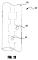
図2Eは、本考案のワイヤ140の他の例示的な実施態様を描写している。この実施態様は図2Bに記載した実施態様と類似するが、この実施態様において、突起147はコア141の全長に沿って延びず、コア141の長さに沿って断続的である。更に、一部の例示的な実施態様において、突起147はコア141の全直径の周りに径方向に延び得るか或いは径方向においてコアの周りに部分的にのみ延び得る。やはり、そのような突起を用いて基質接着及びコア141と基質との間の導電性を向上させ得る。その上、突起147を用いてコアの長さに沿うコア141の断面積を変更し得る。これはワイヤ140とワークピースとの間にアークが創り出されるのを防止するのに役立つ。断面積の変化は、ワイヤの長さに沿うワイヤ140の抵抗の変化をもたらし、よって、ワイヤ140がその融解温度又はその融解温度付近まで加熱されるときのアーク放電(アーキング)を防止するのに役立つ。
FIG. 2E depicts another exemplary embodiment of the
図3は、ワイヤ140を所望の向きに維持するよう突起141Aを受け入れる溝161を有するコンタクトチューブ160を通じる図2Dからのワイヤ140の例示的な実施態様を例示している。具体的には、コア141が垂直に又は(図示のように)水平に向けられた状態でワイヤ140をパッドルに入らせ、それにより、突起141A及び溝161がその所望の向きを維持するのが望ましいことがある。コンタクトチューブ160の構造及び材料は、図3に示す実施態様のための溝161の存在を除き、既知の溶接コンタクトチップの構造及び材料と類似し得る。
FIG. 3 illustrates an exemplary embodiment of the
特定の実施態様を参照して本考案を記載したが、当業者は本考案の範囲から逸脱することなく様々な変更を行い得ること及び均等物を置換し得ることを理解するであろう。加えて、特定の状況又は材料を本考案の教示に適合させるよう、その範囲から逸脱せずに多くの変更を行い得る。従って、本考案は開示の特定の実施態様に限定されず、本考案は付属の請求項の範囲に入る全ての実施態様を含むことが意図される。 Although the present invention has been described with reference to particular embodiments, those skilled in the art will recognize that various changes can be made and equivalents can be substituted without departing from the scope of the invention. In addition, many modifications may be made to adapt a particular situation or material to the teachings of the invention without departing from the scope thereof. Accordingly, the invention is not limited to the specific embodiments disclosed, and the invention is intended to include all embodiments falling within the scope of the appended claims.
100 エネルギ源
110 レーザビーム
115 ワークピース
120 レーザ装置
125 方向
130 レーザ電源
140 抵抗溶接ワイヤ
141 中実な金属コア
141A 突起部分
142’ 露出した縁
142” 露出した縁
143 材料基質
143’ 基質
143” 基質
144 金属粒子
144’ 粒子
144” 粒子
145 突起(複数の突起)
147 突起
150 溶接ワイヤフィーダ
160 コンタクトチューブ
170 ホットワイヤ電源
180 運動コントローラ
190 ロボット
195 コントローラ
DC 直接接触
E 外側縁
S 外表面
100
147
特定の実施態様は、コンシューマブル(消耗品)と、接合、オーバーレイ(overlay)及びクラッディング作業においてコンシューマブルを用いる方法及びシステムとに関する。より具体的には、特定の実施態様は、特別な構成を有するコンシューマブルと、鑞接、クラッディング、肉盛(building-up)、充填(filling)、表面硬化オーバーレイ(hard-facing overlay)、接合及び溶接用途のいずれかのためにホットワイヤシステムにおいてそれらを用いる方法及びシステムとに関する。 Particular embodiments relate to consumables and methods and systems that use consumables in bonding, overlay, and cladding operations. More specifically, certain embodiments include consumables having a special configuration, as well as welding, cladding, building-up, filling, hard-facing overlay, It relates to methods and systems for using them in hot wire systems for either joining and welding applications.
図2A−2Eを今や参照すると、上で参照したシステム100と共に用い得るコンシューマブル(消耗品)の様々な実施態様が示されている。具体的には、図2Aは、中実な金属コア141と、コア141を取り囲む溶接材料基質143(溶接材料マトリクス)とを有する、ワイヤ140の実施態様を例示している。ワイヤ140の外径は、典型的には、既知の溶接コンシューマブルと類似し、例えば、0.89mm〜1.65mm(0.035〜0.065インチ)の範囲内にあるので、既存の溶接ワイヤ送りシステムを利用し得る。もちろん、本考案の実施態様は、必要に応じて、より大きい直径のコンシューマブルを利用し得る。
Referring now to FIGS. 2A-2E, various embodiments of consumables that can be used with the
Claims (15)
外表面を有する中実な金属コアと、
該金属コアの前記外表面に溶着される基質とを含み、該基質は、結合剤と、粒子とを含み、
前記結合剤は、有機結合剤又は重合結合剤のいずれかであり、
前記粒子は導電性であり、0.05mm〜0.5mmの範囲内の公称直径を有し、好ましくは、前記粒子は、0.125mm〜0.3mmの範囲内の又は0.3mm〜0.5mmの範囲内の公称直径を有する、
コンシューマブル。 Consumable for hot wire welding process,
A solid metal core having an outer surface;
A substrate welded to the outer surface of the metal core, the substrate including a binder and particles;
The binder is either an organic binder or a polymeric binder,
The particles are electrically conductive and have a nominal diameter in the range of 0.05 mm to 0.5 mm, preferably the particles are in the range of 0.125 mm to 0.3 mm or from 0.3 mm to 0.3 mm. Having a nominal diameter in the range of 5 mm;
Consumable.
Applications Claiming Priority (3)
| Application Number | Priority Date | Filing Date | Title |
|---|---|---|---|
| US13/835,224 US20140263193A1 (en) | 2013-03-15 | 2013-03-15 | Consumable and method and system to utilize consumable in a hot-wire system |
| US13/835,224 | 2013-03-15 | ||
| PCT/IB2014/000335 WO2014140757A2 (en) | 2013-03-15 | 2014-03-14 | Consumable and method and system to utilize consumable in a hot-wire system |
Publications (1)
| Publication Number | Publication Date |
|---|---|
| JP3205938U true JP3205938U (en) | 2016-08-25 |
Family
ID=50976987
Family Applications (1)
| Application Number | Title | Priority Date | Filing Date |
|---|---|---|---|
| JP2015600148U Expired - Fee Related JP3205938U (en) | 2013-03-15 | 2014-03-14 | Systems that use consumables in consumables and hot wire systems |
Country Status (5)
| Country | Link |
|---|---|
| US (1) | US20140263193A1 (en) |
| JP (1) | JP3205938U (en) |
| CN (1) | CN105263662A (en) |
| DE (1) | DE212014000083U1 (en) |
| WO (1) | WO2014140757A2 (en) |
Cited By (1)
| Publication number | Priority date | Publication date | Assignee | Title |
|---|---|---|---|---|
| JP2016179500A (en) * | 2015-03-23 | 2016-10-13 | リンカーン グローバル, インコーポレイテッドLincoln Global, Inc. | Method and system for additive manufacture using high energy source and hot wire |
Families Citing this family (17)
| Publication number | Priority date | Publication date | Assignee | Title |
|---|---|---|---|---|
| US11344975B2 (en) * | 2015-04-09 | 2022-05-31 | Siemens Energy, Inc. | Optically conductive filler for laser processing |
| US10766091B2 (en) | 2015-04-27 | 2020-09-08 | Lincoln Global, Inc. | Low manganese fume welding process |
| US10675699B2 (en) | 2015-12-10 | 2020-06-09 | Illinois Tool Works Inc. | Systems, methods, and apparatus to preheat welding wire |
| CN106256473B (en) * | 2016-10-20 | 2018-08-03 | 中国科学院重庆绿色智能技术研究院 | A kind of Laser Rapid Prototyping System and method for aluminium wire |
| US10766092B2 (en) | 2017-04-18 | 2020-09-08 | Illinois Tool Works Inc. | Systems, methods, and apparatus to provide preheat voltage feedback loss protection |
| US10870164B2 (en) | 2017-05-16 | 2020-12-22 | Illinois Tool Works Inc. | Systems, methods, and apparatus to preheat welding wire |
| CA3066666A1 (en) | 2017-06-09 | 2018-12-13 | Illinois Tool Works Inc. | Contact tips with screw threads and head to enable unthreading of the screw threads comprising longitudinal slots for gas flow; welding torch with contact tips |
| US11524354B2 (en) | 2017-06-09 | 2022-12-13 | Illinois Tool Works Inc. | Systems, methods, and apparatus to control weld current in a preheating system |
| CN111372711A (en) | 2017-06-09 | 2020-07-03 | 伊利诺斯工具制品有限公司 | Welding torch with first and second contact tips for preheating a welding wire |
| EP3634685B1 (en) | 2017-06-09 | 2022-04-06 | Illinois Tool Works, Inc. | Welding torch, with two contact tips and a plurality of liquid cooling assemblies for conducting current to the contact tips |
| US11590597B2 (en) | 2017-06-09 | 2023-02-28 | Illinois Tool Works Inc. | Systems, methods, and apparatus to preheat welding wire |
| US11020813B2 (en) | 2017-09-13 | 2021-06-01 | Illinois Tool Works Inc. | Systems, methods, and apparatus to reduce cast in a welding wire |
| US20190366480A1 (en) * | 2018-06-04 | 2019-12-05 | Abram Kotliar | Additive manufacturing with metal wire |
| EP3843933A1 (en) | 2018-08-31 | 2021-07-07 | Illinois Tool Works, Inc. | Submerged arc welding systems and submerged arc welding torches to resistively preheat electrode wire |
| US11014185B2 (en) | 2018-09-27 | 2021-05-25 | Illinois Tool Works Inc. | Systems, methods, and apparatus for control of wire preheating in welding-type systems |
| US11897062B2 (en) | 2018-12-19 | 2024-02-13 | Illinois Tool Works Inc. | Systems, methods, and apparatus to preheat welding wire |
| US11772182B2 (en) | 2019-12-20 | 2023-10-03 | Illinois Tool Works Inc. | Systems and methods for gas control during welding wire pretreatments |
Family Cites Families (53)
| Publication number | Priority date | Publication date | Assignee | Title |
|---|---|---|---|---|
| US2180813A (en) * | 1938-02-03 | 1939-11-21 | Gen Motors Corp | Welding electrode |
| US2280223A (en) * | 1939-03-10 | 1942-04-21 | Dumpelmann Richard | Coated electrode and welding rod |
| US2806129A (en) * | 1956-04-24 | 1957-09-10 | Coast Metals Inc | Tungsten carbide weld rods |
| US3023130A (en) * | 1959-08-06 | 1962-02-27 | Eutectic Welding Alloys | Hard surfacing material |
| US3252828A (en) * | 1963-07-30 | 1966-05-24 | Eutectic Welding Alloys | Carbide welding rod |
| US3329487A (en) * | 1965-02-15 | 1967-07-04 | Firth Sterling Inc | Sintered three-phase welding alloy of fe3w3c, wc, and fe |
| US3620830A (en) * | 1968-01-17 | 1971-11-16 | Lincoln Electric Co | Automatic arc welding electrode with an electrically conductive flux coating |
| US3691340A (en) * | 1970-01-13 | 1972-09-12 | Lincoln Electric Co | Welding electrode with lithium shielding metal |
| GB1332506A (en) * | 1970-10-19 | 1973-10-03 | Sumikin Welding Electrode Co | Method of fire cracker arc welding |
| US3766354A (en) * | 1972-03-29 | 1973-10-16 | Great Canadian Oil Sands | Method of manufacturing laminated teeth for bucketwheel excavator using electroslag coating |
| US4055742A (en) * | 1974-05-21 | 1977-10-25 | Union Carbide Corporation | Hard facing rod |
| US4060709A (en) * | 1976-04-28 | 1977-11-29 | Hanson Charles G | Power supply control |
| SU764902A1 (en) * | 1977-06-06 | 1980-10-02 | Ордена Ленина И Ордена Трудового Красного Знамени Институт Электросварки Им. Е.О.Патона | Method of electroslag welding of light metals |
| US4286026A (en) * | 1978-06-08 | 1981-08-25 | Massachusetts Institute Of Technology | Article for implanting radioactive metal on a substrate |
| JPS6011600B2 (en) * | 1978-12-06 | 1985-03-27 | 新日本製鐵株式会社 | Electro gas arc welding method |
| US4650722A (en) * | 1980-06-13 | 1987-03-17 | Union Carbide Corporation | Hard faced article |
| JPS5768296A (en) * | 1980-10-16 | 1982-04-26 | Nissan Motor Co Ltd | Automatic welding wire for surface hardening and overlaying |
| JPS58119464A (en) * | 1982-01-08 | 1983-07-15 | Mitsubishi Electric Corp | Protecting circuit of tig welding power source |
| JPH0679781B2 (en) * | 1984-07-02 | 1994-10-12 | バブコツク日立株式会社 | Hot wire TIG welding equipment |
| US4590358A (en) * | 1984-10-04 | 1986-05-20 | Unimation, Inc. | Apparatus for electrically isolated hot wire surfacing processes |
| CN86101294B (en) * | 1985-02-13 | 1988-11-23 | 巴布考克日立株式会社 | Tungsten arc semiautomatic welding apparatus with inert atmosphere |
| JPS61262469A (en) * | 1985-05-16 | 1986-11-20 | Toyota Motor Corp | Pulse arc welding machine |
| US4683368A (en) * | 1985-06-10 | 1987-07-28 | The Boeing Company | Weld rod |
| FR2590192B1 (en) * | 1985-11-21 | 1991-08-02 | Maybon Guy | FLEXIBLE WELDING STICK WITH COATED METAL CORE, METHOD AND DEVICE FOR PRODUCING THE SAME |
| KR900007264B1 (en) * | 1986-05-30 | 1990-10-06 | 바브콕크-히다찌 가부시기가이샤 | Method of control and apparatus for hot-wire welding |
| US4803334A (en) * | 1987-11-16 | 1989-02-07 | Westinghouse Electric Corp. | Method for laser beam welding metal matrix composite components |
| US5219425A (en) * | 1989-08-25 | 1993-06-15 | Kabushiki Kaisha Kobe Seiko Sho | Flux containing wire for use in stainless steel welding |
| EP0443703B1 (en) * | 1990-02-21 | 1995-03-22 | Kyodo Oxygen Co., Ltd. | Consumable electrode arc welding method and apparatus |
| US5250355A (en) * | 1991-12-17 | 1993-10-05 | Kennametal Inc. | Arc hardfacing rod |
| JPH06235057A (en) * | 1992-12-07 | 1994-08-23 | Ford Motor Co | Combined metallizing line and method for use thereof |
| US6031203A (en) * | 1997-10-22 | 2000-02-29 | Central Motor Wheel Co., Ltd. | Method and apparatus for determining stability of arc welding |
| TW464582B (en) * | 1998-02-17 | 2001-11-21 | Lincoln Global Inc | Welding wire and method of making same |
| US6426483B1 (en) * | 1998-02-17 | 2002-07-30 | Lincoln Global, Inc. | Electrode and method of making same |
| US6127644A (en) * | 1999-04-27 | 2000-10-03 | Stoody Company | Electroslag surfacing using wire electrodes |
| AT410067B (en) * | 2000-11-16 | 2003-01-27 | Fronius Schweissmasch Prod | DEVICE FOR A LASER HYBRID WELDING PROCESS |
| US6521861B2 (en) * | 2000-02-07 | 2003-02-18 | General Electric Company | Method and apparatus for increasing welding rate for high aspect ratio welds |
| US6513728B1 (en) * | 2000-11-13 | 2003-02-04 | Concept Alloys, L.L.C. | Thermal spray apparatus and method having a wire electrode with core of multiplex composite powder its method of manufacture and use |
| SE525658C2 (en) * | 2002-09-16 | 2005-03-29 | Esab Ab | Welding electrode for manual metal arc welding and device in manufacture thereof |
| US7087859B2 (en) * | 2004-05-06 | 2006-08-08 | Lincoln Global, Inc. | Stick electrode |
| AT413667B (en) * | 2004-05-10 | 2006-04-15 | Fronius Int Gmbh | WELDING PROCESS AND LASER HYBRID WELDING BURNER |
| US7271365B2 (en) * | 2005-04-11 | 2007-09-18 | Lincoln Global, Inc. | System and method for pulse welding |
| US20070194087A1 (en) * | 2006-02-23 | 2007-08-23 | Ogborn Jonathan S | Welding electrode rating method using double cap pass test |
| CN101323057A (en) * | 2007-06-13 | 2008-12-17 | 中国船舶重工集团公司第七二五研究所 | High intensity metallic core type seamless flux-cored wire |
| US8063340B2 (en) * | 2008-01-24 | 2011-11-22 | GM Global Technology Operations LLC | Method for controlling the consistency of an arc welding process by monitoring welding voltage to determine weld droplet detachment |
| WO2010021094A1 (en) * | 2008-08-19 | 2010-02-25 | パナソニック株式会社 | Composite welding method and composite welding device |
| US10086461B2 (en) * | 2009-01-13 | 2018-10-02 | Lincoln Global, Inc. | Method and system to start and use combination filler wire feed and high intensity energy source for welding |
| JP5381221B2 (en) * | 2009-03-26 | 2014-01-08 | 株式会社Ihi | Laser welding apparatus and laser welding method |
| US20120325779A1 (en) * | 2011-06-22 | 2012-12-27 | Caterpillar, Inc. | Alloy Depositing Machine And Method Of Depositing An Alloy Onto A Workpiece |
| CN102689106B (en) * | 2012-06-12 | 2014-07-02 | 中冶焊接科技有限公司 | Vertical electro-gas welding metal-cored flux-cored welding wire for petroleum storage tank |
| US20140021187A1 (en) * | 2012-07-19 | 2014-01-23 | Lincoln Global, Inc. | Hot-wire consumable to provide weld with increased wear resistance |
| US9409250B2 (en) * | 2012-08-09 | 2016-08-09 | Lincoln Global, Inc. | Method and system of controlling heating current for hot wire processes |
| US9393644B2 (en) * | 2013-01-31 | 2016-07-19 | Siemens Energy, Inc. | Cladding of alloys using flux and metal powder cored feed material |
| US9203893B2 (en) * | 2013-03-08 | 2015-12-01 | Lincoln Global, Inc. | System and method for installing device drivers on welding equipment |
-
2013
- 2013-03-15 US US13/835,224 patent/US20140263193A1/en not_active Abandoned
-
2014
- 2014-03-14 DE DE212014000083.1U patent/DE212014000083U1/en not_active Expired - Lifetime
- 2014-03-14 JP JP2015600148U patent/JP3205938U/en not_active Expired - Fee Related
- 2014-03-14 CN CN201480028115.XA patent/CN105263662A/en active Pending
- 2014-03-14 WO PCT/IB2014/000335 patent/WO2014140757A2/en active Application Filing
Cited By (1)
| Publication number | Priority date | Publication date | Assignee | Title |
|---|---|---|---|---|
| JP2016179500A (en) * | 2015-03-23 | 2016-10-13 | リンカーン グローバル, インコーポレイテッドLincoln Global, Inc. | Method and system for additive manufacture using high energy source and hot wire |
Also Published As
| Publication number | Publication date |
|---|---|
| DE212014000083U1 (en) | 2015-10-30 |
| CN105263662A (en) | 2016-01-20 |
| WO2014140757A3 (en) | 2014-12-11 |
| WO2014140757A2 (en) | 2014-09-18 |
| US20140263193A1 (en) | 2014-09-18 |
Similar Documents
| Publication | Publication Date | Title |
|---|---|---|
| JP3205938U (en) | Systems that use consumables in consumables and hot wire systems | |
| JP3200613U (en) | System for induction heating of consumables during the laser arc hybrid process | |
| CN106466758B (en) | Additive manufacturing system and method | |
| JP3198728U (en) | Hot wire consumables that provide self-lubricating welds or cladding | |
| US9937580B2 (en) | Method and system for additive manufacturing using high energy source and hot-wire | |
| US10046419B2 (en) | Method and system for additive manufacturing using high energy source and hot-wire | |
| US9833862B2 (en) | Method and system for additive manufacturing using high energy source and hot-wire | |
| CN102271856B (en) | Method and system to start and use a combination filler wire feed and high intensity energy source | |
| JP6750953B2 (en) | Method and system for additive manufacturing using high energy sources and hot wires | |
| US20140008331A1 (en) | Hot-wire consumable incapable of sustaining an arc | |
| JP3204737U (en) | Cored non-arc consumables for bonding or overlay and systems and methods using cored non-arc consumables | |
| CN111050967B (en) | System and method for adaptively controlling preheating of welding wire | |
| US20150209908A1 (en) | Method and system for additive manufacturing using high energy source and hot-wire | |
| US20150209907A1 (en) | Method and system for additive manufacturing using high energy source and hot-wire | |
| US20140021187A1 (en) | Hot-wire consumable to provide weld with increased wear resistance | |
| KR20150037984A (en) | Method of and system for heating consumable during hot wire process using two laser beams | |
| JP2007237225A (en) | High-speed hot wire multi-electrode tig welding method of thin steel plate | |
| JP2007237224A (en) | Tig welding method of thin steel plate | |
| CN114101856A (en) | Welding method of current-carrying hot-fill wire | |
| US10035213B2 (en) | Welding method and welding apparatus | |
| KR101075921B1 (en) | A resistance welding apparutus for welding a resin covered steel plate | |
| Dwivedi et al. | Physics of Welding Arc: Arc Efficiency, Metal Transfer and Melting Rate | |
| JP7238418B2 (en) | Wire feeding tip and wire torch | |
| JPH11104830A (en) | Welding arc length control method and arc welding equipment |
Legal Events
| Date | Code | Title | Description |
|---|---|---|---|
| R150 | Certificate of patent or registration of utility model |
Ref document number: 3205938 Country of ref document: JP Free format text: JAPANESE INTERMEDIATE CODE: R150 |
|
| R250 | Receipt of annual fees |
Free format text: JAPANESE INTERMEDIATE CODE: R250 |
|
| LAPS | Cancellation because of no payment of annual fees |