JP3204973U - Electric rotary tool with screw tightening state judgment function - Google Patents
Electric rotary tool with screw tightening state judgment function Download PDFInfo
- Publication number
- JP3204973U JP3204973U JP2016001299U JP2016001299U JP3204973U JP 3204973 U JP3204973 U JP 3204973U JP 2016001299 U JP2016001299 U JP 2016001299U JP 2016001299 U JP2016001299 U JP 2016001299U JP 3204973 U JP3204973 U JP 3204973U
- Authority
- JP
- Japan
- Prior art keywords
- screw tightening
- electric motor
- rotation amount
- load current
- screw
- Prior art date
- Legal status (The legal status is an assumption and is not a legal conclusion. Google has not performed a legal analysis and makes no representation as to the accuracy of the status listed.)
- Active
Links
Images


Abstract
【課題】ねじ締め作業における適正なねじ締め状態および種々の不適正となるねじ締め状態の判定を行うためのねじ締め状態の目標値の設定を、簡単な操作により行うことができる取扱いの簡便なねじ締め状態判定機能を備えた電動回転工具を提供する。【解決手段】電動モータ12の駆動出力軸にクラッチ機構18を介してドライバービット20を結合し、ドライバービット20の回転に基づくねじ締め回転量を検出する回転量検出手段24を設けて、最初の複数回によるねじ締め操作により、ねじ締めの目標回転量の設定を自動的に行い、その後のねじ締め作業に際して適正なねじ締め状態の良否判定を行うことができるように構成する。【選択図】図1[PROBLEMS] To set a target value of a screw tightening state for determining an appropriate screw tightening state and various unsuitable screw tightening states in screw tightening operations, which can be performed with a simple operation. An electric rotary tool having a screw tightening state determination function is provided. A driver bit 20 is coupled to a drive output shaft of an electric motor 12 via a clutch mechanism 18, and a rotation amount detecting means 24 for detecting a screw tightening rotation amount based on the rotation of the driver bit 20 is provided. A target rotation amount for screw tightening is automatically set by a plurality of screw tightening operations, and an appropriate screw tightening state can be determined in subsequent screw tightening operations. [Selection] Figure 1
Description
本考案は、電動モータの駆動出力軸にクラッチ機構を介してドライバービットを結合し、ねじ締め作業を行うように構成した電動回転工具において、ねじ締め作業における適正なねじ締め状態および種々の不適正となるねじ締め状態について、簡便にして確実に確認および判定することができるように設定することができるねじ締め状態判定機能を備えた電動回転工具に関するものである。 The present invention relates to an electric rotating tool configured to perform screw tightening work by connecting a driver bit to a drive output shaft of an electric motor via a clutch mechanism, and in an appropriate screw tightening state and various inappropriateness It is related with the electric rotary tool provided with the screwing state determination function which can be set so that it can confirm and determine easily and reliably about the screwing state which becomes.
従来において、電動モータ等の駆動手段によりドライバービットを回転駆動してねじ締め作業をするねじ締め装置として、ねじ締め作業を適正にかつ円滑にして迅速に達成することができる種々の機能を備えたねじ締め装置が提案され、実用化されている。 Conventionally, as a screw tightening device that performs screw tightening work by rotationally driving a driver bit by a driving means such as an electric motor, etc., it has various functions that can achieve screw tightening work properly and smoothly and quickly. Screw fastening devices have been proposed and put into practical use.
例えば、電動モータの駆動出力軸にクラッチ機構を介してドライバービットを結合し、ねじ締め作業を行うように構成した電動ドライバーにおいて、所要のねじ取付け対象物に設けられたねじ孔に対し、ねじ締め装置によりねじの締付けを行う場合に、ねじが完全にねじ込まれない状態のままで、所定のねじ締めトルク値に到達して、前記クラッチ機構が作動してねじ締め作業を完了してしまうことがある。 For example, in an electric screwdriver configured to couple a screwdriver bit to a drive output shaft of an electric motor via a clutch mechanism and perform a screw tightening operation, screw tightening is performed with respect to a screw hole provided in a required screw mounting object. When the screw is tightened by the device, the predetermined screw tightening torque value is reached in a state where the screw is not completely screwed, and the clutch mechanism is operated to complete the screw tightening operation. is there.
本出願人は、先に、ねじ孔に対するねじのカジリやねじ浮き等のねじの締付け不良を、容易かつ簡便にして比較的簡単な構成により、低コストで適正かつ確実に検出することができるねじ締め装置を開発し、特許出願を行った(特許文献1参照)。 First, the applicant of the present invention can detect a screw tightening failure such as a screw galling or screw floating in a screw hole easily and simply with a relatively simple configuration at a low cost in an appropriate and reliable manner. A fastening device was developed and a patent application was filed (see Patent Document 1).
すなわち、前記特許文献1に記載のねじ締め装置は、電動モータ等の駆動手段によりドライバービット等の回転工具を回転駆動してねじ締め作業を行うと共に、所要のねじ取付け対象物に対するねじの締め付け完了に伴い前記回転工具に生じる負荷トルクを検出して、前記負荷トルクが予め設定したトルク値に達した際に、前記回転工具の回転駆動を停止制御するように構成してなるねじ締め装置において、(1) 前記回転工具の回転駆動に伴う回転数や回転時間に基づく回転量を検出するために前記回転工具または駆動手段に回転量検出手段を設け、(2) 回転工具の先端部にねじ頭部を嵌合させたねじのねじ軸先端をねじ取付け対象物のねじ孔に位置決め当接した時点において、前記回転工具を軸方向に押圧することによりねじ締め基準時点(t1)をねじ締め基準時点設定手段により設定するように構成したものである。
That is, the screw tightening device described in
そして、(3) 前記ねじ締め基準時点設定手段によりねじ締め基準時点が設定された後において、前記回転工具の駆動手段を始動させてねじ締め始動時点(t2)をねじ締め始動時点設定手段により設定し、(4) 前記回転工具の回転駆動により前記ねじ孔に位置決め当接したねじを回動させて前記回転工具に生じる負荷トルクが予め設定したトルク値に達した際のねじ締め完了時点(t3)をねじ締め完了時点検出手段により検出し、(5) 前記ねじ締め基準時点設定手段によるねじ締め基準時点(t1)の設定後において、前記ねじ締め始動時点設定手段により回転工具の駆動手段を始動させるねじ締め始動時点(t2)から、前記ねじ締め完了時点検出手段により検出されるねじ締め完了時点(t3)まで、前記回転量検出手段により検出される回転工具の回転量が、予め設定した基準値と比較してその許容範囲内にあるか否かを判定してねじ締めの良否をねじ締め良否判定手段により判定するように構成したものである。 (3) After the screw tightening reference time is set by the screw tightening reference time setting means, the driving means of the rotary tool is started and the screw tightening start time (t2) is set by the screw tightening start time setting means. (4) A screw tightening completion time (t3) when a load torque generated in the rotary tool reaches a preset torque value by rotating the screw positioned and abutting on the screw hole by the rotational drive of the rotary tool. ) Is detected by the screw tightening completion time detection means, and (5) after setting the screw tightening reference time (t1) by the screw tightening reference time setting means, the screw tightening start time setting means starts the driving means of the rotary tool. From the screw tightening start time (t2) to be detected to the screw tightening completion time (t3) detected by the screw tightening completion time detecting means, the rotation amount detecting means detects Rotation of the rolling tool, is obtained by constituting the quality of screw tightening by determining whether compared with a preset reference value is within the allowable range to determine the screwing quality determining means.
また、前記特許文献1に記載のねじ締め装置において、前記ねじ締め完了時点検出手段として、回転工具を回転駆動する駆動手段の駆動軸と回転工具との軸結合部に設けたトルク設定クラッチ機構により、予め設定したトルク設定値に到達した際にクラッチ動作した際のねじ締め完了時点検出信号とすること、または回転工具を回転駆動する電動モータの負荷電流を検出する負荷電流検出手段により、予め設定した負荷電流値に到達した際のねじ締め完了時点検出信号とすることが、それぞれ開示されている。
Further, in the screw tightening device described in
前述したように、前記特許文献1に記載のねじ締め装置においては、ねじ締め基準時点(t1)を設定すると共に、ねじ締め始動時点(t2)からねじ締め完了時点(t3)まで、回転量検出手段により検出される回転工具の回転量が、予め設定した基準値と比較してその許容範囲内にあるか否かを判定して、ねじ孔に対するねじのカジリやねじ浮き等のねじの締付け不良を、容易かつ簡便にして比較的簡単な構成により、低コストで適正かつ確実に検出することができるものである。
As described above, in the screw tightening device described in
しかしながら、前記ねじ締め装置においては、それぞれのねじ締め作業において、ねじ締め基準時点(t1)を設定し、そしてねじ締め始動時点(t2)からねじ締め完了時点(t3)まで、回転量検出手段により検出される回転工具の回転量を検出することから、常にねじ締め基準時点(t1)の設定を行う作業に注意を払う必要があり、熟練作業者においては特に問題はないが、不慣れな作業者においてのねじ締め作業においては、前記発明において発揮される適正な作業効果および作業能率を得られなくなる場合が考えられる。
However, in the screw tightening device, in each screw tightening operation, the screw tightening reference time (t1) is set, and from the screw tightening start time (t2) to the screw tightening complete time (t3), the rotation amount detecting means Since the detected amount of rotation of the rotating tool is detected, it is necessary to always pay attention to the work of setting the screw tightening reference time point (t1), and there is no particular problem for skilled workers, but unskilled workers In the screw tightening work in
そこで、本考案者は、前述した従来において種々提案されているクラッチ機構を採用した電動ドライバーにおいて、ドライバービットを回転駆動する電動モータの制御回路に対して電動モータの回転量を検出する回転量検出手段を設けて、ねじ締め作業において、前記電動モータの回転量を検出記録するように設定し、ねじ締めの完了する状態を前記クラッチ機構のクラッチ動作により検出して、このクラッチ動作時点での電動モータのねじ締め開始時点からの回転量を逐次検出ないし記録する制御部を設けた電動ドライバーを構成することに着目した。 Therefore, the inventor of the present invention, in the electric driver employing the above-described variously proposed clutch mechanisms, detects the amount of rotation of the electric motor with respect to the control circuit of the electric motor that rotates the driver bit. Means for detecting and recording the amount of rotation of the electric motor in the screw tightening operation, detecting the completion of screw tightening by the clutch operation of the clutch mechanism, and We paid attention to the construction of an electric driver provided with a control unit for sequentially detecting or recording the rotation amount from the start of the screw tightening of the motor.
すなわち、本考案においては、前記構成からなる電動ドライバーを使用して、所定のねじ締め作業を行う開始に際して、最初に複数回の予備的なねじ締め操作を行って、それぞれねじ締め開始時点から回転量検出手段により電動モータの回転量の検出を開始し、次いでねじ締めの完了する状態を前記クラッチ機構のクラッチ動作により検出して、このクラッチ動作時点での電動モータのねじ締め開始時点からの回転量をそれぞれ検出記録し、これらの検出記録した複数回のねじ締め回転量状態が全て適正であったことを条件として、前記検出記録した回転量に基づいて目標回転量を自動的に設定する。そして、その後における所定のねじ締め作業において、それぞれねじ締め作業の開始時点からねじ締めを完了して前記クラッチ機構のクラッチ動作時点に至るまでの電動モータの回転量を逐次検出し、前記クラッチ動作時点に検出された回転量を前記目標回転量と比較することにより、ねじ締め状態の適否を適正に判定することができることを突き止めた。 In other words, in the present invention, when the predetermined screw tightening operation is started using the electric screwdriver having the above-described configuration, first, a plurality of preliminary screw tightening operations are performed, and the rotation is started from the start of each screw tightening. The detection of the amount of rotation of the electric motor is started by the amount detection means, and then the completion of screw tightening is detected by the clutch operation of the clutch mechanism, and the rotation of the electric motor from the start of screw tightening at the time of the clutch operation is detected. Each amount is detected and recorded, and the target rotation amount is automatically set based on the detected and recorded rotation amount on condition that all of the detected and recorded screw tightening rotation amount states are all appropriate. Then, in a predetermined screw tightening operation thereafter, the rotation amount of the electric motor from the start of the screw tightening operation to the clutch operation time of the clutch mechanism is sequentially detected, and the clutch operation time It was found that the appropriateness of the screw tightening state can be properly determined by comparing the detected rotation amount with the target rotation amount.
なお、本考案において、前記最初に複数回の予備的なねじ締め操作を行うに際して、前記クラッチ機構においては、予め標準的なトルク調整を施して置くものとし、また、その後に設定された前記目標回転量(許容範囲を含む)に基づいて、所定のねじ締め作業において検出されたねじ締め回転量につき、それぞれねじ締め状態を判定することにより、前記目標回転量(許容範囲を含む)に適合することにより適正なねじ締め状態とすることを容易かつ確実に判定することができる。 In the present invention, when the preliminary screw tightening operation is performed a plurality of times for the first time, the clutch mechanism is preliminarily subjected to standard torque adjustment, and the target set thereafter is set. Based on the rotation amount (including the allowable range), the screw tightening state is determined for each screw tightening rotation amount detected in the predetermined screw tightening operation, so that the target rotation amount (including the allowable range) is satisfied. Therefore, it can be easily and reliably determined that the screw is properly tightened.
また、本考案においては、電動モータに設定された停動トルクに基づいて、ねじ締めの完了に伴い電動モータの回転駆動が停動トルクに達することにより、その回転停止状態となることを、エンコーダ等によって検出することができることから、前記クラッチ機構によるクラッチ動作時点の検出を行うことに代えて、電動モータの停動トルクに基づく回転停止時点の検出を行うことによっても、ねじ締め開始時点からねじ締めの完了に伴う電動モータの回転量の検出を適正に行うことも可能である。 Further, in the present invention, based on the stationary torque set for the electric motor, the rotation stop of the electric motor reaches the stationary torque when the screw tightening is completed, and the rotation is stopped. Therefore, instead of detecting the clutch operation time by the clutch mechanism, it is also possible to detect the rotation stop time based on the stopping torque of the electric motor, and to It is also possible to appropriately detect the amount of rotation of the electric motor accompanying the completion of tightening.
なお、前記のように予め設定される目標回転量に対し、それぞれ所定のねじ締め作業において前記クラッチ動作時点または前記電動モータの停動トルクに基づく回転停止時点までに、逐次検出される電動モータの回転量を比較する場合において、前記目標回転量の設定値から所定のねじ締め作業においてクラッチ動作時点または電動モータの回転停止時点までに検出される電動モータの回転量を、逐次加算または逐次減算するように演算し、最終的な回転量の検出値を前記目標回転量(許容範囲を含む)の設定値と比較するように構成することができる。 In addition, with respect to the target rotation amount set in advance as described above, each of the electric motors sequentially detected by the predetermined screw tightening operation until the clutch operation time or the rotation stop time based on the stop torque of the electric motor. When comparing the rotation amount, the rotation amount of the electric motor detected from the set value of the target rotation amount to the clutch operation time or the electric motor rotation stop time in a predetermined screw tightening operation is sequentially added or subtracted. The final rotation amount detection value can be compared with the set value of the target rotation amount (including the allowable range).
本考案においては、前記構成からなる電動回転工具において、負荷電流検出手段を設けてねじ締めトルク値に比例する負荷電流値を、前記ねじ締め回転量と同様のタイミングで検出記録するように設定し、前記電動モータの回転量を検出記録する回転量検出手段と共に、前記電動モータの回転量と負荷電流値とを検出して、予め設定した目標回転量(許容範囲を含む)と比較すると共に、予め設定した目標負荷電流値(許容範囲を含む)とも比較することにより、ねじ締め状態の良否を判定し、さらにクラッチ動作時の負荷電流値を検出して、前記判定結果を表示するように設定することができる。 In the present invention, in the electric rotary tool having the above-described configuration, load current detection means is provided so that the load current value proportional to the screw tightening torque value is detected and recorded at the same timing as the screw tightening rotation amount. Along with the rotation amount detection means for detecting and recording the rotation amount of the electric motor, the rotation amount of the electric motor and the load current value are detected and compared with a preset target rotation amount (including an allowable range). It is set to display the determination result by comparing the pre-set target load current value (including the allowable range) to determine whether the screw tightening state is good or not, and detecting the load current value during clutch operation. can do.
また、本考案においては、前記電動回転工具において、ねじの取付け対象物に対するドライバービットの当接時において作動する操作スイッチまたはエンコーダ、あるいは前記当接時において軸方向の変位により作動するプッシュ操作スイッチを設けて、その動作信号を検出することにより、ねじ締め作業を行う際のねじ締め開始時点として設定することができる。 Further, in the present invention, in the electric rotary tool, an operation switch or an encoder that is operated when the driver bit is in contact with an object to be screwed, or a push operation switch that is operated by an axial displacement at the time of the contact. By providing and detecting the operation signal, it can be set as the screw tightening start time when the screw tightening operation is performed.
このようにして、ねじ締め作業を行う際のねじ締め開始時点を設定することは、電動ドライバーによるねじ締め作業において、回転量検出手段により検出される電動モータの回転量を検出記録する際に、電動モータを駆動するための駆動スイッチをスイッチ操作部材で操作すると同時に、前記回転量検出手段により電動モータの回転量が検出されることになる。これにより、例えば、ドライバービットをねじ取付け対象物に当接するまで空転させている場合には、この空転しているタイミングにおいて検出される回転量が、実際にねじ締め作業を行っている間の電動モータの回転量を不正確とすることから、前記のようにねじ締め開始時点を設定することにより、実際にねじ締め作業を行っている間の電動モータの回転量を正確に検出することが可能となる。 In this way, setting the screw tightening start time when performing the screw tightening operation is performed when detecting and recording the rotation amount of the electric motor detected by the rotation amount detection means in the screw tightening operation by the electric screwdriver. At the same time that the drive switch for driving the electric motor is operated by the switch operating member, the rotation amount of the electric motor is detected by the rotation amount detecting means. As a result, for example, when the driver bit is idled until it abuts against the object to be screwed, the rotation amount detected at the idle rotation timing is the electric amount during the actual screw tightening operation. Since the rotation amount of the motor is inaccurate, it is possible to accurately detect the rotation amount of the electric motor during the actual screw tightening operation by setting the screw tightening start time as described above. It becomes.
特に、前記のようにプッシュ操作スイッチの動作信号を検出することにより、最初に、ドライバービットをねじの取付け対象物に当接した際に、ねじ締め作業を行う場合のねじ締め開始時点を設定し、次いで電動モータを駆動するための駆動スイッチを操作することにより、ねじの着座に至るまでの実際にねじ締め作業を行っている間の電動モータの回転量を正確に検出することができる。 In particular, by detecting the operation signal of the push operation switch as described above, the screw tightening start time when the screw tightening operation is performed when the screwdriver bit is first brought into contact with the screw mounting target is set. Then, by operating a drive switch for driving the electric motor, it is possible to accurately detect the rotation amount of the electric motor during the actual screw tightening operation until the screw is seated.
従って、本考案によれば、マイクロメータに見られるように、精密ねじにおいては、ねじのピッチ寸法に関する加工精度の向上に伴い、前述したねじの回転量の検出精度の向上と相まって、ねじ締めに際してのねじの回転量とねじ軸の移動距離との関係が高精度に対応する位置決め設定が可能となり、これによりねじ締めの際にねじがその取付け対象物に対して適正に着座状態となる位置と回転量の関係を、正確に設定および確認することができ、ねじ締め作業における良否判定の信頼性を十分に高めることができる。 Therefore, according to the present invention, as seen in a micrometer, in precision screws, along with the improvement of the processing accuracy related to the pitch dimension of the screw, in conjunction with the improvement of the detection accuracy of the amount of rotation of the screw described above, The positioning of the screw rotation amount and the screw shaft movement distance can be set with high accuracy, so that when the screw is tightened, the screw is properly seated with respect to its mounting object. The relationship of the rotation amount can be set and confirmed accurately, and the reliability of the quality determination in the screw tightening operation can be sufficiently enhanced.
従って、本考案の目的は、電動モータの駆動出力軸にクラッチ機構を介してドライバービットを結合し、ねじ締め作業を行うように構成した電動回転工具において、簡便にして確実に確認および判定することができるように設定することができるねじ締め状態判定機能を備えた電動回転工具を提供することにある。 Accordingly, an object of the present invention is to simply and surely confirm and determine in an electric rotary tool configured to couple a driver bit to a drive output shaft of an electric motor via a clutch mechanism and perform a screw tightening operation. An object of the present invention is to provide an electric rotary tool having a screw tightening state determination function that can be set so that
前記目的を達成するため、本考案の請求項1に記載のねじ締め状態判定機能を備えた電動回転工具は、電動モータと、この電動モータを駆動するための駆動スイッチと、前記電動モータの駆動出力軸に減速機構およびクラッチ機構を介して結合されるドライバービットとを備え、前記駆動スイッチを操作するスイッチ操作部材と、前記クラッチ機構のクラッチ動作を検出するクラッチ動作検出センサと、前記電動モータの駆動および停止制御を行う電動モータ制御回路と、前記電動モータの回転量を検出する回転量検出手段と、をそれぞれ設けた電動回転工具からなり、
前記ドライバービットのねじの取付け対象物に対する当接時に作動する駆動スイッチまたはエンコーダを設け、前記操作スイッチまたはエンコーダの動作信号によりねじ締めを行う際のねじ締め開始時点を検出記録するねじ締め開始時点記憶手段と、
最初の複数回によるねじ締め操作により、前記ねじ締め開始時点からねじ締めの完了に伴う前記クラッチ機構によるクラッチ動作時点までのドライバービットの回転に対する電動モータの回転量を、前記回転量検出手段により検出し、この検出された回転量を記録すると共に、前記複数回のねじ締め状態が全て適正であることを条件に目標回転量(許容範囲を含む)を設定する回転量記憶手段と、
その後のねじ締め作業において、前記ねじ締め開始時点からねじ締めの完了に伴う前記クラッチ機構によるクラッチ動作時点までのドライバービットの回転に対する電動モータの回転量を前記回転量検出手段により逐次検出して前記回転量記憶手段に記録すると共に、前記検出された回転量を前記設定された目標回転量(許容範囲を含む)と比較することにより、ねじ締め状態の良否を判定するように制御する制御手段と、を設けたことを特徴とする。
In order to achieve the above object, an electric rotary tool having a screw tightening state determining function according to
A screw tightening start time memory for detecting and recording a screw tightening start time when screw tightening is performed by an operation signal of the operation switch or encoder, provided with a drive switch or an encoder that operates when the screw of the screwdriver bit is in contact with an object to be mounted. Means,
The rotation amount detecting means detects the rotation amount of the electric motor relative to the rotation of the driver bit from the start time of the screw tightening to the clutch operation time due to the completion of the screw tightening by the screw tightening operation by the first plural times. A rotation amount storage means for recording the detected rotation amount and setting a target rotation amount (including an allowable range) on condition that the plurality of screw tightening states are all appropriate;
In the subsequent screw tightening operation, the rotation amount detection means sequentially detects the rotation amount of the electric motor relative to the rotation of the driver bit from the screw tightening start time to the clutch operation time by the clutch mechanism when the screw tightening is completed. Control means for controlling the screw tightening state to be judged by recording the rotation amount in the rotation amount storage means and comparing the detected rotation amount with the set target rotation amount (including an allowable range); Are provided.
本考案の請求項2に記載のねじ締め状態判定機能を備えた電動回転工具は、電動モータと、この電動モータを駆動するための駆動スイッチと、前記電動モータの駆動出力軸に減速機構を介して結合されるドライバービットとを備え、前記駆動スイッチを操作するスイッチ操作部材と、前記電動モータの停動トルクに基づく回転停止状態を検出するエンコーダと、前記電動モータの駆動および停止制御を行う電動モータ制御回路と、前記電動モータの回転量を検出する回転量検出手段と、をそれぞれ設けた電動回転工具からなり、
前記ドライバービットのねじの取付け対象物に対する当接時に作動する駆動スイッチまたはエンコーダを設け、前記操作スイッチまたはエンコーダの動作信号によりねじ締めを行う際のねじ締め開始時点を検出記録するねじ締め開始時点記憶手段と、
最初の複数回によるねじ締め操作により、前記ねじ締め開始時点からねじ締めの完了に伴う前記電動モータの停動トルクに基づく回転停止時点までのドライバービットの回転による電動モータの回転量を、前記回転量検出手段により検出し、この検出された前記回転量を記録すると共に、前記複数回のねじ締め状態が全て適正であることを条件に目標回転量(許容範囲を含む)を設定する回転量記憶手段と、
その後のねじ締め作業において、前記ねじ締め開始時点からねじ締めの完了に伴う前記電動モータの停動トルクに基づく回転停止時点までのライバービットの回転による電動モータの回転量を前記回転量検出手段により逐次検出して前記回転量記憶手段に記録すると共に、前記検出された回転量を前記設定された目標回転量(許容範囲を含む)と比較することにより、ねじ締め状態の良否を判定するように制御する制御手段と、を設けたことを特徴とする。
According to a second aspect of the present invention, there is provided an electric rotary tool having a screw tightening state determination function, an electric motor, a drive switch for driving the electric motor, and a drive output shaft of the electric motor via a reduction mechanism. And a driver bit coupled to each other, a switch operating member that operates the drive switch, an encoder that detects a rotation stop state based on a stop torque of the electric motor, and an electric motor that controls driving and stop of the electric motor An electric rotary tool provided with a motor control circuit and a rotation amount detection means for detecting the rotation amount of the electric motor,
A screw tightening start time memory for detecting and recording a screw tightening start time when screw tightening is performed by an operation signal of the operation switch or encoder, provided with a drive switch or an encoder that operates when the screw of the screwdriver bit is in contact with an object to be mounted. Means,
The rotation amount of the electric motor due to the rotation of the driver bit from the start time of the screw tightening to the stop time of the rotation based on the stop torque of the electric motor accompanying the completion of the screw tightening is determined by the screw tightening operation by the first multiple times. Rotation amount storage which detects by the amount detection means, records the detected rotation amount, and sets a target rotation amount (including an allowable range) on condition that the plurality of screw tightening states are all appropriate. Means,
In the subsequent screw tightening operation, the rotation amount detection means detects the rotation amount of the electric motor due to the rotation of the driver bit from the start time of the screw tightening to the rotation stop time based on the stop torque of the electric motor accompanying the completion of the screw tightening. Sequentially detecting and recording in the rotation amount storage means, and comparing the detected rotation amount with the set target rotation amount (including an allowable range) to determine whether the screw tightening state is good or bad. And a control means for controlling.
本考案の請求項3に記載のねじ締め状態判定機能を備えた電動回転工具は、前記請求項1記載のねじ締め状態判定機能を備えた電動回転工具において、前記電動モータ制御回路において前記、ドライバービットに付与される負荷トルク(反力)に基づく電動モータにおいて得られる負荷電流を検出する負荷電流検出手段を設け、
最初の複数回によるねじ締め操作により、前記ねじ締め開始時点からねじ締めの完了に伴う前記クラッチ機構によるクラッチ動作時点における電動モータのねじ締めトルク値に比例する負荷電流値を、前記負荷電流検出手段により検出し、この検出された負荷電流値を記録すると共に、前記複数回のねじ締め状態が全て適正であることを条件に目標負荷電流値(許容範囲を含む)を設定する負荷電流値記憶手段を設け、
前記制御手段には、その後のねじ締め作業において、前記ねじ締めの開始時点からねじ締めの完了に伴う前記クラッチ機構によるクラッチ動作時点における電動モータのねじ締めトルク値に比例する負荷電流値を前記負荷電流検出手段により逐次検出して前記負荷電流値記憶手段に記録すると共に、前記検出された負荷電流値を前記設定された目標負荷電流値(許容範囲を含む)と比較することにより、ねじ締め状態の良否を判定するように制御する構成としたことを特徴とする。
According to a third aspect of the present invention, there is provided an electric rotary tool having a screw tightening state determination function according to the first aspect of the present invention, wherein the electric rotary tool has a screw tightening state determination function according to the first aspect. A load current detecting means for detecting a load current obtained in the electric motor based on a load torque (reaction force) applied to the bit;
A load current value proportional to a screw tightening torque value of the electric motor at the time of clutch operation by the clutch mechanism accompanying the completion of screw tightening from the start of screw tightening by a plurality of first screw tightening operations is calculated as the load current detecting means. Load current value storage means for recording the detected load current value and setting a target load current value (including an allowable range) on the condition that the plurality of screw tightening states are all appropriate. Provided,
In the subsequent screw tightening operation, the control means receives a load current value proportional to the screw tightening torque value of the electric motor from the start of the screw tightening to the time of clutch operation by the clutch mechanism accompanying the completion of the screw tightening. By sequentially detecting the current detection means and recording it in the load current value storage means, and comparing the detected load current value with the set target load current value (including an allowable range), It is characterized in that the control is performed so as to determine whether the quality is good or bad.
本考案の請求項4に記載のねじ締め状態判定機能を備えた電動回転工具は、前記請求項2記載のねじ締め状態判定機能を備えた電動回転工具において、前記電動モータ制御回路において前記、ドライバービットに付与される負荷トルク(反力)に基づく電動モータにおいて得られる負荷電流を検出する負荷電流検出手段を設け、
最初の複数回によるねじ締め操作により、前記ねじ締め開始時点からねじ締めの完了に伴う前記電動モータの停動トルクに基づく回転停止時点における電動モータのねじ締めトルク値に比例する負荷電流値を、前記負荷電流検出手段により検出し、この検出された負荷電流値を記録すると共に、前記複数回のねじ締め状態が全て適正であることを条件に目標負荷電流値(許容範囲を含む)を設定する負荷電流値記憶手段を設け、
前記制御手段には、その後のねじ締め作業において、前記ねじ締めの開始時点からねじ締めの完了に伴う前記電動モータの停動トルクに基づく回転停止時点における電動モータのねじ締めトルク値に比例する負荷電流値を前記負荷電流検出手段により逐次検出して前記負荷電流値記憶手段に記録すると共に、前記検出された負荷電流値を前記設定された目標負荷電流値(許容範囲を含む)と比較することにより、ねじ締め状態の良否を判定するように制御する構成としたことを特徴とする。
According to a fourth aspect of the present invention, there is provided an electric rotary tool having a screw tightening state determining function according to the present invention. The electric rotary tool having the screw tightening state determining function according to the second aspect, wherein the driver in the electric motor control circuit is A load current detecting means for detecting a load current obtained in the electric motor based on a load torque (reaction force) applied to the bit;
The load current value proportional to the screw tightening torque value of the electric motor at the rotation stop time based on the stop torque of the electric motor accompanying the completion of screw tightening from the screw tightening start time by the screw tightening operation by the first multiple times, Detected by the load current detecting means, records the detected load current value, and sets a target load current value (including an allowable range) on condition that the plurality of screw tightening states are all appropriate. Provide load current value storage means,
In the control means, in a subsequent screw tightening operation, a load proportional to the screw tightening torque value of the electric motor at the rotation stop time based on the stop torque of the electric motor accompanying the completion of screw tightening from the start time of the screw tightening. Current values are sequentially detected by the load current detection means and recorded in the load current value storage means, and the detected load current value is compared with the set target load current value (including an allowable range). Thus, the control is performed so as to determine whether the screw tightening state is good or bad.
本考案の請求項5に記載のねじ締め状態判定機能を備えた電動回転工具は、前記ドライバービットのねじの取付け対象物に対する当接時に作動する駆動スイッチとして、ドライバービットの軸方向の変位によって作動するプッシュ操作スイッチを設け、前記プッシュ操作スイッチの動作信号により、ねじ締めを行う際のねじ締め開始時点を設定する構成としたことを特徴とする。 According to a fifth aspect of the present invention, there is provided an electric rotary tool having a screw tightening state determination function, which is operated by an axial displacement of a driver bit as a drive switch that operates when the screw of the driver bit is brought into contact with an object to be attached. A push operation switch is provided, and a screw tightening start time when screw tightening is set by an operation signal of the push operation switch.
本考案の請求項6に記載のねじ締め状態判定機能を備えた電動回転工具は、前記制御手段において、その後のねじ締め作業に際し、前記回転量記憶手段に記録される前記クラッチ動作時点または前記停動トルクに基づく回転停止時点に検出される電動モータの回転量が、設定された目標回転量(許容範囲を含む)に適合すると判定された場合、および/または、前記負荷電流値記憶手段に記録される前記クラッチ動作時点または前記停動トルクに基づく回転停止時点に検出される電動モータのねじ締めトルク値に比例する負荷電流検出値が、設定された目標負荷電流値(許容範囲を含む)に適合すると判定された場合には、ねじ締め状態を適正と判定し記録ないし表示する構成としたことを特徴とする。 According to a sixth aspect of the present invention, there is provided an electric rotary tool having a screw tightening state determination function, wherein the control means records the clutch operation time point or the stoppage recorded in the rotation amount storage means during a subsequent screw tightening operation. When it is determined that the rotation amount of the electric motor detected at the time of rotation stop based on the dynamic torque matches the set target rotation amount (including the allowable range), and / or recorded in the load current value storage means The load current detection value proportional to the screw tightening torque value of the electric motor detected at the clutch operation time or the rotation stop time based on the stop torque is set to the set target load current value (including the allowable range). When it is determined that it is suitable, the screw tightening state is determined to be appropriate and recorded or displayed.
本考案の請求項7に記載のねじ締め状態判定機能を備えた電動回転工具は、前記制御手段において、その後のねじ締め作業に際し、前記回転量記憶手段に記録される前記クラッチ動作時もしくはその不動作時、または前記停動トルクに基づく回転停止時もしくはその不動作時の電動モータの回転量が、設定された目標回転量(許容範囲を含む)に適合しないと判定された場合、および/または、前記負荷電流値記憶手段に記録される前記クラッチ動作時点または前記停動トルクに基づく回転停止時点の電動モータのねじ締めトルク値に比例する負荷電流検出値が、設定された目標負荷電流値(許容範囲を含む)に適合しないと判定された場合には、ねじ締め状態を不良と判定し記録ないし表示する構成としたことを特徴とする。 According to a seventh aspect of the present invention, there is provided an electric rotary tool having a screw tightening state determining function, wherein the control means performs a subsequent screw tightening operation during or after the clutch operation recorded in the rotation amount storage means. When it is determined that the amount of rotation of the electric motor during operation or when the rotation is stopped or not based on the stationary torque does not match the set target rotation amount (including the allowable range), and / or The load current detection value proportional to the screw tightening torque value of the electric motor at the clutch operation time or the rotation stop time based on the stall torque recorded in the load current value storage means is set as a set target load current value ( If it is determined that it does not conform to (including the allowable range), the screw tightening state is determined to be defective, and is recorded or displayed.
本考案の請求項8に記載のねじ締め状態判定機能を備えた電動回転工具は、前記制御手段において、ねじ締め状態を適正と判定された場合に、ねじ締め状態が適正と判定されたねじの本数および/またはその長さ寸法を検出記録する構成としたことを特徴とする。
The electric rotary tool having the screw tightening state determination function according to
本考案の請求項1および2に記載のねじ締め状態判定機能を備えた電動回転工具によれば、電動モータの駆動出力軸にクラッチ機構を介してドライバービットを結合し、ねじ締め作業を行うように構成した電動回転工具を使用して、最初のねじ締め操作として、前記クラッチ機構によるクラッチ動作をクラッチ動作検出センサにより検出して、前記電動モータの回転量検出手段により得られる回転量検出信号に基づく回転量を検出する操作を、複数回繰り返し行うことによって、前記回転量の検出記録に基づいて目標回転量(許容範囲を含む)の設定を行って、その後のねじ締め作業において、検出される回転量を前記設定された目標回転量(許容範囲を含む)と比較を行うことによって、ねじ締め状態の良否を適正にして容易かつ簡便に確認することができる。従って、本考案の電動回転工具を使用すれば、ねじ締め作業の未熟練者においても、容易かつ正確なねじ締め作業を達成することができる。 According to the electric rotary tool having the screw tightening state determination function according to the first and second aspects of the present invention, the screwdriver is connected to the drive output shaft of the electric motor via the clutch mechanism to perform the screw tightening operation. As the first screw tightening operation, the clutch operation by the clutch mechanism is detected by the clutch operation detection sensor, and the rotation amount detection signal obtained by the rotation amount detection means of the electric motor is used. The operation for detecting the rotation amount based on the rotation amount is repeated a plurality of times to set the target rotation amount (including the allowable range) based on the detection record of the rotation amount, and is detected in the subsequent screw tightening operation. By comparing the rotation amount with the set target rotation amount (including the permissible range), it is possible to easily and simply confirm the quality of the screw tightening state appropriately. It can be. Therefore, if the electric rotating tool of the present invention is used, even an unskilled screw tightening operator can easily and accurately perform the screw tightening operation.
本考案の請求項2に記載のねじ締め状態判定機能を備えた電動回転工具によれば、電動モータの駆動出力軸にクラッチ機構を設けることなくドライバービットを結合し、ねじ締め作業を行うように構成した電動回転工具を使用して、最初のねじ締め操作として、前記電動モータの停動トルクに基づいてその回転停止状態を検出して、前記電動モータの回転量検出手段により得られる回転量検出信号に基づく回転量を検出する操作を、複数回繰り返し行うことによって、前記回転量の検出記録に基づいて目標回転量(許容範囲を含む)の設定を行って、その後のねじ締め作業において、検出される回転量を前記設定された目標回転量(許容範囲を含む)と比較を行うことによって、ねじ締め状態の良否を適正にして容易かつ簡便に確認することができる。従って、本考案の電動回転工具を使用すれば、ねじ締め作業の未熟練者においても、容易かつ正確なねじ締め作業を達成することができる。
According to the electric rotary tool having the screw tightening state determination function according to
本考案の請求項3および4に記載のねじ締め状態判定機能を備えた電動回転工具によれば、前述した電動回転工具の構成において、クラッチ機構によるクラッチ動作をクラッチ動作検出センサにより検出した際に、または電動モータの停動トルクに基づいてその回転停止状態を検出した際に、電動モータ制御回路における負荷電流検出手段により得られる負荷電流検出信号に基づく負荷電流値の検出を、前記回転量の検出と同時に行うことによって、前記目標回転量(許容範囲を含む)の設定と共に、目標負荷電流値(許容範囲を含む)の設定行い、その後のねじ締め作業において、検出される回転量および負荷電流値を、前記目標回転量(許容範囲を含む)および目標負荷電流値(許容範囲を含む)とそれぞれ比較することにより、前記と同様にねじ締め状態の良否を適正にして容易かつ簡便に確認することができる。 According to the electric rotary tool having the screw tightening state determination function according to the third and fourth aspects of the present invention, when the clutch operation by the clutch mechanism is detected by the clutch operation detection sensor in the configuration of the electric rotary tool described above. Alternatively, when the rotation stop state is detected based on the stationary torque of the electric motor, the load current value is detected based on the load current detection signal obtained by the load current detection means in the electric motor control circuit. By performing the detection simultaneously with the detection, the target rotation amount (including the allowable range) and the target load current value (including the allowable range) are set, and the rotation amount and the load current detected in the subsequent screw tightening operation. By comparing the value with the target rotation amount (including the allowable range) and the target load current value (including the allowable range), respectively, It can be confirmed in the proper quality of the screw tightening state as easily and conveniently.
本考案の請求項5に記載のねじ締め状態判定機能を備えた電動回転工具によれば、実際にねじ締め作業を行っている間の電動モータの回転量を正確に検出することが可能となり、これに基づいて種々のねじ締めの異常状態の検出を容易化し、ねじ締め作業における適正なねじ締め状態について確実に確認および判定することができる。このようにして、本考案によれば、使用するクラッチ方式の電動回転工具において検出される制御に関するデータの集積ないし画像処理を円滑かつ容易に達成し、電動回転工具としての制御データ処理機能を高めることができる。
According to the electric rotary tool having the screw tightening state determination function according to
本考案の請求項6および7に記載のねじ締め状態判定機能を備えた電動回転工具によれば、それぞれ前述したねじ締め状態の良否判定と共に、例えば、電動モータの回転量が目標回転量(許容範囲を含む)よりも少ない場合は、ねじのカジリ、ねじ浮き、選択したねじ寸法の不適合等の異常状態とし、また電動モータの回転量が目標回転量(許容範囲を含む)よりも多い場合は、ねじバカ、下穴の摩損、ねじのカムアウト、ビットの破損、選択したねじ寸法の不適合等の異常状態として、それぞれねじ締め不良の判定を容易に行うことができる。従って、本考案によれば、前述したねじ締め作業における不良率の低減と共に、人的および物的な作業ミスの検出および確認についても、容易に行うことができる。
According to the electric rotary tool having the screw tightening state determination function according to
本考案の請求項8に記載のねじ締め状態判定機能を備えた電動回転工具によれば、前述したように、ねじ締め状態の良否判定を極めて容易かつ正確に行うことができることから、特にねじ締め状態が適正と判定されたねじの本数を、異常ないし不良と判定されたねじの本数と区別して、制御部において確実に記録することができると共に、これらの記録されたねじの本数を確認ないし表示することにより、ねじ締め作業の効率化と共にその信頼性を高めることができる。また、前記と同様に、ねじ締め状態が適正と判定された場合に、クラッチ動作時に検出された回転量に基づいて、ねじ締めを行ったねじの長さ寸法を、制御手段により正確に記録し、さらに記録されたその記録内容を表示することができる。 According to the electric rotary tool having the screw tightening state determination function according to the eighth aspect of the present invention, as described above, the quality determination of the screw tightening state can be performed very easily and accurately. The number of screws judged to be proper can be distinguished from the number of screws judged to be abnormal or defective, and can be recorded reliably in the control unit, and the number of these recorded screws can be confirmed or displayed. By doing so, the reliability of the screw tightening operation can be improved as well as the efficiency. Similarly to the above, when the screw tightening state is determined to be appropriate, the length of the screw tightened screw is accurately recorded by the control means based on the rotation amount detected during the clutch operation. Further, the recorded contents recorded can be displayed.
次に、本考案に係るねじ締め状態判定機能を備えた電動回転工具の実施例につき、添付図面を参照しながら以下詳細に説明する。 Next, an embodiment of an electric rotary tool having a screw tightening state determination function according to the present invention will be described in detail with reference to the accompanying drawings.
[ねじ締め状態判定機能を備えた電動回転工具の構成例(1)]
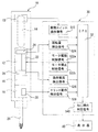
図1は、本考案に係るねじ締め状態判定機能を備えた電動回転工具の実施例を示す概略構成説明図である。すなわち、図1において、参照符号10は電動回転工具を示し、この電動回転工具10の把持部内に、電動モータ12と、この電動モータ12を駆動するための駆動スイッチ13と、前記電動モータ12の駆動出力軸(図示せず)に結合される減速機構16およびクラッチ機構18とを、それぞれ内蔵し、前記クラッチ機構18を介してドライバービット20を結合した構成からなる。
[ Configuration example (1) of an electric rotary tool having a screw tightening state determination function ]
FIG. 1 is a schematic configuration explanatory view showing an embodiment of an electric rotary tool having a screw tightening state determination function according to the present invention. That is, in FIG. 1,
前記電動回転工具10においては、前記電動モータ12の駆動スイッチ13を操作するスイッチ操作部材14と、電動モータ12の駆動制御および停止制御を行う電動モータ制御回路22と、前記クラッチ機構18のクラッチ動作を検出するクラッチ動作検出センサ28とがそれぞれ設けられる。そして、前記電動モータ制御回路22には、前駆電動モータ12の回転量を検出する回転量検出手段24が設けられる。さらに、前記ドライバービット20に付与される負荷トルク(反力)に基づいて電動モータ12において得られる負荷電流を検出する負荷電流検出手段26が適宜設けられる。
In the
なお、本実施例の電動回転工具10において、電動モータ12としてはブラシレスモータを好適に使用することができる。また、前記電動モータ12を駆動するために、前記駆動スイッチ13を操作するスイッチ操作部材14としては、例えば電動回転工具10の把持部外周に設ける公知のレバー部材として構成することができる。
In the
また、本実施例において、前記電動モータ12の回転量を検出するための回転量検出手段24は、ブラシレスモータにおけるロータの磁極を検出するホール素子に対して、磁極検出時に発生するパルスをカウントする手段として設けることができる。この場合、前記回転量検出手段24により検出される前記パルスのカウント数は、ドライバービット20の回転に伴うねじ締め作業に際してのねじ締め回転量と相関する回転量として、検出記録することができる。
Further, in this embodiment, the rotation amount detection means 24 for detecting the rotation amount of the
さらに、前記電動モータ12の負荷電流を検出するための負荷電流検出手段26は、電動モータ12の電源回路において負荷電流を検出する手段として設けることができる。この場合、検出される前記電動モータ12の負荷電流値は、ドライバービット20の回転に伴うねじ締め作業に際してのねじ締めトルク値と相関する負荷電流値として、検出記録することができる。
Furthermore, the load current detection means 26 for detecting the load current of the
前記クラッチ機構18としては、例えば減速機構16の出力軸にクラッチ板を取付け、このクラッチ板に対してクラッチボールを軸方向に弾力的に係合させる構成とし、ねじ締め作業において、ドライバービット20を介して前記出力軸に一定以上の負荷トルク(反力)が掛ると、前記クラッチ板がクラッチボールを乗り越えて、ドライバービット20を係合保持するビットホルダに対する回転駆動力の伝達が遮断されることにより、ねじを予め設定したトルクにより締め付けることができるように構成される。この場合、前記クラッチボールをクラッチ板に対して弾力的に係合する際に、その弾力を適宜調整することにより、ねじ締めトルクを設定することができる。
As the
そして、前記クラッチ機構18のクラッチ動作を検出するクラッチ動作検出センサ28としては、例えばクラッチ動作時点のクラッチ板の変位により作動するリミットスイッチや、クラッチ動作時点において空転する減速機構16を構成するインターナルギヤの回動を検出する磁気センサ等の公知の手段によって構成することができる。
The clutch
そこで、本実施例においては、ねじ締め状態を判定するための制御手段として制御部30を設け、CPU32において、前記電動回転工具10における電動モータ12に設けた電動モータ制御回路22に対して、ねじ締め作業を開始する際に、前記スイッチ操作部材14によって操作される駆動スイッチ13の動作によって得られる駆動スイッチ操作信号S13を入力し、この駆動スイッチ操作信号S13に基づいて、モータ駆動制御信号S22a を出力すると共に前記電動モータ制御回路22に入力して、電動モータ12の駆動制御を行うように構成される。
Therefore, in the present embodiment, a
前記電動モータ12の駆動により、所要のねじ締め作業を行う場合、前記CPU32において、ねじ締め作業の開始に伴う電動モータ12の駆動開始時点t0 において、前記回転量検出手段24により検出される回転量検出信号S24に基づいて、電動モータ12の回転量Rt を検出記録するように設定する。
When the required screw tightening operation is performed by driving the
また、前記と同様に、ねじ締め作業の開始に伴う電動モータ12の駆動開始時点t0 において、前記負荷電流検出手段26により検出される負荷電流検出信号S26に基づいて、ねじ締めトルク値に比例する負荷電流値It を検出記録するように設定する。
Further, similarly to the above, at the driving start time t0 of the
そして、前記CPU32においては、前記クラッチ機構18のクラッチ動作時点にクラッチ動作検出センサ28により検出されるクラッチ動作検出信号S28に基づいて得られるクラッチ動作時点t1 において、電動モータ12の回転量を検出して、後述する目標回転量Rm±α(±αは許容範囲)の設定と、この目標回転量Rm±αと比較するための回転量Rt1 とをそれぞれ検出記録するように設定する。
The
また、前記と同様に、前記クラッチ機構18のクラッチ動作時点にクラッチ動作検出センサ28により検出されるクラッチ動作検出信号S28に基づいて得られるクラッチ動作時点t1 において、ねじ締めトルク値に比例する負荷電流値を検出して、後述する目標負荷電流値Im±β(±βは許容範囲)の設定と、この目標負荷電流値Im±βと比較するための負荷電流値It1 とをそれぞれ検出記録するように設定する。
Similarly to the above, the load current proportional to the screw tightening torque value at the clutch operation time t1 obtained based on the clutch operation detection signal S28 detected by the clutch
なお、前述したように、クラッチ動作検出センサ28によりクラッチ動作が検出された際に、CPU32を介して、モータ停止制御信号S22b が出力されると共に前記電動モータ制御回路22に入力されて、電動モータ12の停止制御が行われるように構成される。
As described above, when the clutch operation is detected by the clutch
さらに、本実施例においては、前述したように、制御部30のCPU32において、予め設定された目標回転量Rm±αに対してクラッチ動作時点t1 に検出される回転量Rt1 を比較することにより、ねじ締め状態の良否が判定された場合、および/または、予め設定された目標負荷電流値Im±βに対してクラッチ動作時点t1 に検出される負荷電流値It1 を比較することにより、ねじ締め状態の良否が判定された場合、CPU32から出力される前記いずれかのねじ締め判定信号S40により、それぞれの判定内容を適宜表示器40において表示するように構成する。
Further, in the present embodiment, as described above, the
次に、前記構成からなる本考案に係るねじ締め状態判定機能を備えた電動回転工具の制御操作方法について、ねじ締め作業におけるねじ締め状態の良否判定を行うまでのステップについて、前記制御部30の制御系統図とその制御操作を示すフローチャートに基づいて説明する。 Next, regarding the control operation method of the electric rotary tool having the screw tightening state determination function according to the present invention having the above-described configuration, the steps until the pass / fail determination of the screw tightening state in the screw tightening operation is performed. Description will be made based on a control system diagram and a flowchart showing its control operation.
[本考案に係る電動回転工具の制御操作方法(1)]
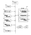
図2は、図1に示す本考案に係るねじ締め状態判定機能を備えた電動回転工具の制御部30の制御系統を示し、図3は、図1に示す本考案に係るねじ締め状態判定機能を備えた電動回転工具の前記制御部30の制御操作方法を示すフローチャートである。
[ Control operation method of electric rotating tool according to the present invention (1) ]
2 shows a control system of the
図2において、本考案の制御部30の制御系統において、CPU32は全体を制御するプロセッサを示し、データバスを介して前述した操作スイッチ(エンコーダ)13、回転量検出手段24、負荷電流検出手段26、電動モータ制御回路24が接続されている。また、前記CPU32のデータバスには、制御プログラムが記憶されるROM50が接続されると共に、前記操作スイッチ(エンコーダ)13、回転量検出手段24、負荷電流検出手段26により検出される電動回転工具10の動作に伴う検出データ等を格納する記憶手段としてのRAM60が接続されている。
In FIG. 2, in the control system of the
すなわち、前記RAM60には、ねじ締め開始時点を記録し設定するねじ締め開始時点記憶部61と、回転量検出手段24により検出される回転量を記録すると共に目標回転量を設定する回転量記憶部62と、負荷電流検出手段26により検出される負荷電流値を記録すると共に目標負荷電流値を設定する負荷電流値記憶部63とが設けられている。
That is, in the
さらに、前記CPU32のデータバスには、前記RAM60に格納される各種データに基づいて外部表示を行うための表示器としてのLCD40aがその制御回路としてのLCDIC40bを介して接続されると共に、適宜外部操作器によってデータ等の入出力を行う入出力回路52が接続される。
Further, an LCD 40a as a display for performing external display based on various data stored in the
次に、本考案に係る電動回転工具10の制御操作方法として、前記図1の構成および図2示す制御部30の制御系に基づいて、図3に示す制御操作方法を説明する。
Next, as a control operation method of the
先ず、本考案に係る電動回転工具10の駆動に際しては、スイッチ操作部材14を操作することにより駆動スイッチ13を作動し、前記電動モータ制御回路22にモータ駆動制御信号S22a が入力されて、電動モータ12の駆動制御が行われ、電動ドライバー10の駆動が開始される(図1、図2参照)。なお、前記電動回転工具10の最初の使用に際しては、クラッチ機構18に対して予め標準的なトルク調整を施しておくものとする。
First, when driving the
そこで、本考案の電動回転工具10を最初に使用するに際しては、最初のねじ締め操作として、所要のねじ締め対象物に対するねじ締め操作を1回からn回の複数回に亘って行う(STEP−1)。この場合、電動回転工具10に設けられた駆動スイッチ13の作動により、電動モータ12の駆動開始時点となるねじ締め開始時点t0 を検出し、RAM60のねじ締め開始時点記憶部61に記録する(図2参照)。
Therefore, when the
同時に、電動回転工具10に設けられた回転量検出信号S24により、ねじ締めを行うドライバービット20の回転量に比例する電動モータ12の回転量のカウントを開始する。そして、前記ドライバービット20によるねじ締めが行われ、クラッチ機構18によるクラッチ動作が行われる時点t1 までにカウントされたねじ締め回転量を、それぞれRAM60の回転量記憶部62に記録する(STEP−2)。
At the same time, the rotation amount detection signal S24 provided in the
このようにして、前記複数回に亘って行われたねじ締め操作において、ねじ締め状態が全て適正に行われたことを条件に、それぞれ前記回転量記憶部62に記録されたねじ締め回転量に基づいて、前記回転量記憶部62において目標回転量Rm±α(±αは許容範囲)として自動的に設定される(STEP−3)。 In this way, in the screw tightening operation performed a plurality of times, the screw tightening rotation amount recorded in the rotation amount storage unit 62 is set on the condition that all the screw tightening states are properly performed. Based on this, the rotation amount storage unit 62 automatically sets the target rotation amount Rm ± α (± α is an allowable range) (STEP-3).
以上のようにして、本考案の電動回転工具10において、前記目標回転量Rm±α(±αは許容範囲)が設定されることにより、その後における所要のねじ締め作業を行うことができる(STEP−4)。従って、その後の電動回転工具10による所要のねじ締め作業を行う際には(STEP−4)、前述した場合と同様に、ねじ締め開始時点t0 をからクラッチ機構18によるクラッチ動作が行われる時点t1 までにカウントされたねじ締め回転量を検出して、前記回転量記憶部62に記録する(STEP−5)。
As described above, in the
このようにして検出されたねじ締め回転量Rt1は、前記前記回転量記憶部62に設定された目標回転量Rm±α(±αは許容範囲)と比較され(STEP−6)、その結果に基づいて、ねじ締め状態の良否を判定するように設定される。すなわち、前記検出されたねじ締め回転量Rt1と、目標回転量Rm±α(±αは許容範囲)との比較に際しては、Rm+α≧Rt1 ≧Rm−αの条件を満足すれば、適正なねじ締め状態と判定され(STEP−7)、前記条件を満足しない場合には、不良ないし異常なねじ締め状態と判定される(STEP−8)。 The screw tightening rotation amount Rt1 thus detected is compared with the target rotation amount Rm ± α (± α is an allowable range) set in the rotation amount storage unit 62 (STEP-6). Based on this, it is set to determine whether the screw tightening state is good or bad. That is, when comparing the detected screw tightening rotation amount Rt1 with the target rotation amount Rm ± α (± α is an allowable range), if the condition of Rm + α ≧ Rt1 ≧ Rm−α is satisfied, proper screw tightening is performed. If the condition is not satisfied (STEP-7) and the condition is not satisfied, it is determined that the screw is in a defective or abnormal screw tightening state (STEP-8).
なお、電動回転工具10の使用によるねじ締め操作およびその後のねじ締め作業の開始(STEP−1およびSTEP−4)に際し、前記回転量検出手段24により検出される回転量検出信号S24に基づいて電動モータ12の回転量Rt を、回転量記憶部61において記録する場合において、ドライバービット20がねじの取付け対象物に当接してから、実際にねじ締め作業を行っている間の電動モータ12の回転量Rt を検出すれば、正確な回転量を検出することができる。
It should be noted that, when the screw tightening operation by using the
そこで、本考案の電動回転工具10においては、例えば、本出願人が特許第4721535号において提案したように、前記電動ドライバー10において、ねじの取付け対象物に対するドライバービット20の当接時における軸方向の変位によって作動するプッシュ操作スイッチ(図示せず)を設けて、このプッシュ操作スイッチの動作信号により、ねじ締め作業を行う際のねじ締め開始時点t0 を設定することができる。
Therefore, in the
このようにして、ねじ締め状態の良否が判定された場合、適正判定と不良判定とを明確に区別し得る判定表示を行うことができる。そこで、本考案に係る電動回転工具10においては、制御部30において出力される前記いずれかのねじ締め判定信号S40により、それぞれの判定内容を適宜表示器としてのLCD40aにより表示するように構成することができる(図1、図2参照)。
In this way, when it is determined whether the screw tightening state is good or bad, a determination display that can clearly distinguish between the appropriateness determination and the failure determination can be performed. Therefore, the
[本考案に係る電動回転工具の制御操作方法(2)]
図4は、図1に示す本考案に係る電動回転工具の前記制御部30の別の制御操作方法を示すフローチャートである。すなわち、図4に示す制御操作方法は、前記図3に示す制御操作方法を基本とし、さらに追加される制御操作方法を示すものである。
[ Control operation method of the electric rotary tool according to the present invention (2) ]
FIG. 4 is a flowchart showing another control operation method of the
そこで、図4に示す制御操作は、前記制御操作方法(1)と同様に並行して行うものである。従って、電動回転工具10の最初の使用に際しての最初のねじ締め操作により、所要のねじ締め対象物に対するねじ締め操作を1回からn回の複数回に亘って行う場合(STEP−11)において、前記制御操作方法と同様にして、電動回転工具10に設けられた駆動スイッチ13の作動により、電動モータ12の駆動開始時点となるねじ締め開始時点t0 を検出し、RAM60のねじ締め開始時点記憶部61に記録する(図2参照)。
Therefore, the control operation shown in FIG. 4 is performed in parallel with the control operation method (1). Therefore, in the case where the screw tightening operation for the required screw tightening object is performed once to n multiple times by the first screw tightening operation at the first use of the electric rotary tool 10 (STEP-11), In the same manner as in the control operation method, the screw tightening start time t0 that is the drive start time of the
また、同時に電動回転工具10に設けられた負荷電流検出手段26により、電動モータ12のねじ締めトルク値に比例する負荷電流値It の検出を開始する。そして、前記ドライバービット20によるねじ締めが行われ、クラッチ機構18によるクラッチ動作が行われる時点t1 までに逐次検出された電動モータ12の負荷電流値を、それぞれRAM60の負荷電流値記憶部63に記録する(STEP−12)。
At the same time, detection of the load current value It proportional to the screw tightening torque value of the
このようにして、前記複数回に亘って行われたねじ締め操作において、ねじ締め状態が全て適正に行われたことを条件に、それぞれ前記負荷電流値記憶部63に記録された負荷電流値に基づいて、前記負荷電流値記憶部63において目標負荷電流値Im±β(±βは許容範囲)として自動的に設定される(STEP−13)。 In this way, in the screw tightening operation performed a plurality of times, the load current values recorded in the load current value storage unit 63 are respectively set on condition that all the screw tightening states are properly performed. Based on this, the load current value storage unit 63 automatically sets the target load current value Im ± β (± β is an allowable range) (STEP-13).
以上のようにして、本考案の電動回転工具10において、前記目標負荷電流値Im±β(許容範囲を含む)が設定されることにより、その後における所要のねじ締め作業を行うことができる(STEP−14)。従って、その後の電動回転工具10による所要のねじ締め作業を行う際には(STEP−14)、前述した場合と同様に、ねじ締め開始時点t0 をからクラッチ機構18によるクラッチ動作が行われる時点t1 までの電動モータ12の負荷電流値It1を逐次検出して、前記回転量記憶部63に記録する(STEP−15)。
As described above, in the
このようにして検出された負荷電流値It1は、前記前記負荷電流値記憶部63に設定された目標負荷電流値IRm±β(±βは許容範囲)と比較され(STEP−16)、その結果に基づいて、ねじ締め状態の良否を判定するように設定される。すなわち、前記検出された負荷電流値It1と、目標負荷電流値Im±β(±βは許容範囲)との比較に際しては、Im+β≧It1 ≧Im−βの条件を満足すれば、適正なねじ締め状態と判定され(STEP−17)、前記条件を満足しない場合には、不良ないし異常なねじ締め状態と判定される(STEP−18)。 The load current value It1 thus detected is compared with the target load current value IRm ± β (± β is an allowable range) set in the load current value storage unit 63 (STEP-16), and as a result. Is set to determine whether the screw tightening state is good or bad. That is, when comparing the detected load current value It1 and the target load current value Im ± β (± β is an allowable range), if the condition of Im + β ≧ It1 ≧ Im−β is satisfied, proper screw tightening is performed. If the condition is not satisfied (STEP-17) and the condition is not satisfied, it is determined to be a defective or abnormal screw tightening state (STEP-18).
なお、本考案の前述した電動回転工具10においては、前記制御操作方法(2)は、前述した制御操作方法(1)と同時に並行して実施される。
In the above-described electric
すなわち、最初の複数回によるねじ締め操作においては、前記ねじ締め開始時点t0 からねじ締めの完了に伴う前記クラッチ機構18によるクラッチ動作時点t1 までのドライバービット20の回転による電動モータ12の回転量Rt1を、前記回転量検出手段24により検出し、この検出された回転量を記録すると共に前記複数回のねじ締め状態が全て適正であることを条件に目標回転量Rm±α(±αは許容範囲)を回転量記憶部62に設定する。同時に、前記負荷電流検出手段26により検出される電動モータ12のねじ締めトルク値に比例する負荷電流値It1を検出し、この検出された負荷電流値を記録すると共に前記複数回のねじ締め状態が全て適正であることを条件に目標負荷電流値IRm±β(±βは許容範囲)を負荷電流値記憶部63に設定する。
That is, in the first plural screw tightening operations, the rotation amount Rt1 of the
その後のねじ締め作業において、前記ねじ締め開始時点からねじ締めの完了に伴う前記クラッチ機構18によるクラッチ動作時点までのドライバービット20の回転による電動モータの回転量Rt1を、前記回転量検出手段24により逐次検出して前記回転量記憶部62に記録すると共に、前記クラッチ動作時点に検出された回転量を、前記設定された目標回転量Rm±α(±αは許容範囲)と比較する。同時に、前記ねじ締めの開始時点からねじ締めの完了に伴う前記クラッチ機構によるクラッチ動作時点までの負荷電流値It1を、前記負荷電流検出手段26により逐次検出して前記負荷電流値記憶部63に記録すると共に、前記クラッチ動作時点に検出された負荷電流値を、前記設定された目標負荷電流値IRm±β(±βは許容範囲)と比較する。そして、それぞれねじ締め状態の良否を制御部30により判定し、相互に適正なねじ締め状態となることについての確認をすることができる。
In the subsequent screw tightening operation, the rotation amount detection means 24 determines the rotation amount Rt1 of the electric motor due to the rotation of the
従って、前記制御操作方法(2)においても、ねじ締め状態の良否が判定された場合、制御部30において出力される前記いずれかのねじ締め判定信号S40により、それぞれの判定内容を適宜表示器としてのLCD40aにより表示するように構成することができる(図1、図2参照)。
Therefore, also in the control operation method (2), when it is determined whether the screw tightening state is good or bad, each determination content is appropriately displayed by the one of the screw tightening determination signals S40 output from the
前述した実施例において、本考案に係る電動回転工具においては、その基本的な構成として、クラッチ機構18を設けると共に、前記クラッチ機構18のクラッチ動作を検出するクラッチ検出センサ28を設けることにより、ねじ締めの開始時点からねじ締めの完了に伴うドライバービット20の回転に対する電動モータ12の回転量、さらには前記ドライバービット20に付与される負荷トルク(反力)に基づく電動モータの負荷電流値を検出する場合について説明した。
In the embodiment described above, in the electric rotary tool according to the present invention, as a basic configuration thereof, the
しかるに、電動モータ12に設定された停動トルクに基づいて、ねじ締めの完了に伴い電動モータの回転駆動が停動トルクに達することにより、その回転停止状態となることを、電動モータ12に設けたエンコーダ等によって検出することができることから、前記電動モータ12の停動トルクに基づく回転停止時点の検出を行うことによっても、ねじ締め開始時点からねじ締めの完了に伴う電動モータ12の前記回転量の検出ないし電動モータ12の前記負荷電流値の検出を適正に行うことも可能である。
However, the
従って、前述した実施例において、前記クラッチ機構およびクラッチ検出センサを設けることに代えて、ねじ締め開始時点からねじ締めの完了に伴う前記電動モータの停動トルクに基づく回転停止時点までのドライバービットの回転に対する電動モータの回転量を検出するように構成すること、および、ねじ締め開始時点からねじ締めの完了に伴う前記電動モータの停動トルクに基づく回転停止時点における電動モータのねじ締めトルク値に比例する負荷電流値を検出するように構成することができる。 Therefore, in the above-described embodiment, instead of providing the clutch mechanism and the clutch detection sensor, the driver bit of the rotation from the screw tightening start time to the rotation stop time based on the stop torque of the electric motor accompanying the completion of screw tightening is changed. It is configured to detect the amount of rotation of the electric motor with respect to the rotation, and the screw tightening torque value of the electric motor at the time of rotation stop based on the stop torque of the electric motor accompanying the completion of screw tightening from the time of screw tightening start. It can be configured to detect a proportional load current value.
〔ねじ締め状態判定機能を備えた電動回転工具の構成例(2)〕
図5は、本考案に係るねじ締め状態判定機能を備えた電動回転工具の別の実施例を示す概略構成説明図である。なお、説明の便宜上、前述した図1に示す実施例の装置と、同一の構成要素については、それぞれ同一の機能を有することから、同一の参照符号を付し、それらの詳細な説明は省略する。
[ Configuration example (2) of an electric rotary tool having a screw tightening state determination function ]
FIG. 5 is a schematic configuration explanatory diagram showing another embodiment of the electric rotary tool having a screw tightening state determination function according to the present invention. For convenience of explanation, the same constituent elements as those of the apparatus of the embodiment shown in FIG. 1 described above have the same functions, and thus the same reference numerals are given and detailed descriptions thereof are omitted. .
すなわち、本実施例の電動ドライバー10´において、電動モータ12としてブラシレスモータ以外の電動モータの適用を可能とするため、電動モータ12の回転量検出手段としては、前記電動モータ12の駆動軸に対し公知のロータリエンコーダからなる第1のエンコーダ25を付設した構成からなるものである。従って、本実施例において、前記電動モータ12の回転量は、制御部30のCPU32に対して、前記第1のエンコーダ25により検出されるエンコーダ検出信号S25を入力することにより、回転量検出手段として設定することができる。この場合、前記第1のエンコーダ25により検出されるエンコーダ検出信号S25は、電動モータ12により回転するドライバービット20のねじ締め作業に際してのねじ締め回転量と相関する回転量として、検出記録することができる。
That is, in the
また、本実施例の電動ドライバー10´においては、ドライバービット20の回転量検出手段として、ドライバービット20と結合する公知のロータリエンコーダからなる第2のエンコーダ29を付設した構成とすることができる。従って、前記ドライバービット20の回転量は、制御部30のCPU32に対して、前記第2のエンコーダ29により検出されるエンコーダ検出信号S29を入力することにより、回転量検出手段として設定することができる。この場合、前記第2のエンコーダ29により検出されるエンコーダ検出信号S29は、ドライバービット20の回転によるねじ締め作業に際してのねじ締め回転量と相関する回転量として、検出記録することができる。
Further, in the
本実施例の電動回転工具10´において、その他の構成については、前記実施例と同一であり、従って、制御部30のCPU32においては、前記実施例と同様に、予め設定された目標回転量Rm±αに対してクラッチ動作時点t1 において検出される回転量Rt1 を比較することにより、前述したそれぞれのねじ締め状態の良否が判定された場合、および/または、予め設定された目標負荷電流値Im±βに対してクラッチ動作時点t1 において検出される負荷電流値It1 を比較することにより、前述したそれぞれのねじ締め状態の良否が判定された場合、CPU32から出力される前記いずれかのねじ締め判定信号S40により、それぞれの判定内容を適宜表示器40において表示するように構成される。
The other configuration of the
なお、本実施例に示すように、ドライバービット20のねじ締め操作およびねじ締め作業に際してのねじ締め回転量と相関する回転量を検出する前記第1のエンコーダ25または前記第2のエンコーダ29を使用することにより、ねじ締めを行う際のねじ締め開始時点t0 を適正かつ容易に検出記録することができる。
As shown in the present embodiment, the
以上の実施例から明らかなように、本考案に係る電動回転工具によれば、各種のねじ等を使用する所定のねじ締め作業において、所要のねじ孔に対するねじ締めの開始からねじが着座するまでの電動モータの回転量の検出に際して、ほぼ50%程度まで確認することができれば、ねじ締め作業において生じるねじ締め不良となるトラブルの半分を確認し解決することができる。すなわち、ねじ締め作業の四大トラブルと称される、(1) ねじの下穴への斜め締めによりその入り口で生じるねじのカジリ、(2) タッピンねじ等の締め付けに際して発生するワークと下穴の不具合により着座前にトルクアップしてしまうねじ浮きを、それぞれ確認することができる。これらのトラブルは、ねじ締めの開始より、ねじの長さ寸法の半分くらいの間に起生するものである。そして、これらの状況をクリアして、ねじ着座後の規定のねじ締めトルクに達するまでに、(3) ビットの摩耗等によりカムアウトが発生して規定のねじ締めトルクに達成することができない場合、(4) 下穴の摩損によるねじの締結不良等、電動モータの回転量とクラッチ機構によるトルクアップ信号の検出および確認により、前記のようなねじ締め作業の四大トラブルを、それぞれ熟練を必要とすることなく、容易かつ確実に検出することができるという、優れた作用効果が得られるものである。 As is clear from the above embodiments, according to the electric rotary tool according to the present invention, in a predetermined screw tightening operation using various screws or the like, from the start of screw tightening to a required screw hole until the screw is seated. If the amount of rotation of the electric motor can be detected up to about 50%, half of the trouble that results in screw tightening failure in the screw tightening operation can be confirmed and solved. In other words, it is called the four major troubles of screw tightening, (1) screw galling generated at the entrance by slant tightening to the pilot hole of the screw, and (2) work piece and pilot hole generated when tightening the tapping screw etc. It is possible to confirm each of the screw floats that torque up before sitting due to a problem. These troubles occur during about half the length of the screw from the start of screw tightening. And when these conditions are cleared and the specified screw tightening torque after screw seating is reached, (3) If the camout occurs due to bit wear etc. and the specified screw tightening torque cannot be achieved, (4) By detecting and confirming the amount of rotation of the electric motor and the torque-up signal by the clutch mechanism, such as poor screw fastening due to wear of the pilot hole, the above four major troubles of screw tightening work require skill respectively. Therefore, it is possible to obtain an excellent effect that detection can be performed easily and reliably.
また、本発考案に係る電動回転工具によれば、所要のねじ締め作業において、予め設定される複数本のねじを、順次ねじ締めを行うに際して、それぞれのねじについての前述したねじ締め状態の良否の判定を検出記録すると同時に、ねじ締め本数の検出記録も一括して行うことができ、各種のねじ締め作業を行う生産ラインおよびそれらのネットワークにおける生産管理システムの構築を容易に実現することが可能となる。 Further, according to the electric rotary tool according to the present invention, when the plurality of preset screws are sequentially tightened in the required screw tightening operation, the above-described screw tightening state of each screw is acceptable. At the same time, the detection and recording of the screw tightening can be performed at the same time, and the number of screw tightening can be detected and recorded at the same time, making it easy to build a production management system for various screw tightening operations and their networks. It becomes.
特に、本考案に係る電動回転工具によれば、所要のねじ締め作業において、電動ドライバーによる電動モータの回転量を、クラッチ機構を利用して適正に検出することにより、適正なねじ締め完了(ねじの着座)状態を容易かつ確実に判定して、多数の連続ねじ締めを行うねじの本数との関係において、それぞれのねじ締め状態を記録ないし表示することができる。また、それぞれのねじ締め作業におけるクラッチ動作時点において、電動モータの負荷電流を検出記録することにより、前記クラッチ動作時点の負荷電流値は、それぞれねじ締めを完了(着座)したねじのねじ締めトルク値と極めて正確な相関関係を以って確認することができるため、前記電動モータの回転量の検出と共に電動モータの負荷電流値をそれぞれ組合せて検出記録ないし表示するように設定することにより、各種のねじ締め作業を行う生産ラインおよびそれらのネットワークにおける生産管理システムの構築を容易に実現することが可能となる。 In particular, according to the electric rotary tool according to the present invention, in the required screw tightening operation, the proper screw tightening completion (screw tightening operation) is achieved by properly detecting the rotation amount of the electric motor by the electric screwdriver using the clutch mechanism. It is possible to easily and reliably determine the (sitting) state, and to record or display each screwing state in relation to the number of screws to be subjected to many continuous screwing. Also, by detecting and recording the load current of the electric motor at the time of clutch operation in each screw tightening operation, the load current value at the time of clutch operation is the screw tightening torque value of the screw that has been completely screwed (seated), respectively. Therefore, various settings can be made by detecting the amount of rotation of the electric motor and setting the load current value of the electric motor to be detected and recorded or displayed in combination with the detection of the rotation amount of the electric motor. It becomes possible to easily construct a production management system in a production line for performing screw tightening work and a network thereof.
以上、本考案の好適な実施例として、通常のねじ穴を設けた対象物に通常のねじを使用してねじ締め制御を行う場合について説明したが、このような実施例に限定されることなく、例えばタッピンねじやドリルねじを使用するねじ締め制御あるいはタップによるねじ加工を行う電動回転工具としても、同様に適用することができる。 As described above, as a preferred embodiment of the present invention, the case where screw tightening control is performed using an ordinary screw on an object provided with an ordinary screw hole has been described, but the present invention is not limited to such an embodiment. For example, the present invention can be similarly applied to an electric rotary tool that performs screw tightening control using a tapping screw or a drill screw or performs screw processing using a tap.
10,10´ 電動回転工具 12 電動モータ
13 駆動スイッチ 14 スイッチ操作部材
16 減速機構 18 クラッチ機構
20 ドライバービット 22 電動モータ制御回路
24 回転量検出手段 25 第1のエンコーダ(回転量検出手段)
26 負荷電流検出手段 28 クラッチ動作検出センサ
29 第2のエンコーダ(回転量検出手段)
30 制御部 32 CPU
40 表示器
40a LCD 40b LCDIC
50 ROM 52 入出力回路
60 RAM 61 ねじ締め開始時点記憶部
62 回転量記憶部 63 負荷電流値記憶部
S13 駆動スイッチ操作信号
S22a モータ駆動制御信号 S22b モータ停止制御信号
S24 回転量検出信号 S25 エンコーダ検出信号
S26 負荷電流検出信号 S28 クラッチ動作検出信号
S29 エンコーダ検出信号 S40 ねじ締め状態判定信号
Rm±α 目標回転量(許容範囲を含む)
Im±β 目標負荷電流値(許容範囲を含む)
t0 電動モータ駆動開始時点/ねじ締め開始時点
t1 クラッチ動作時点
Rt1 クラッチ動作時点の回転量
It1 クラッチ動作時点の負荷電流検出値
DESCRIPTION OF
26 Load current detection means 28 Clutch
30
40
50 ROM 52 I /
Im ± β Target load current value (including allowable range)
t0 Electric motor drive start time / screw tightening start time t1 Clutch operation time Rt1 Rotation amount at clutch operation time It1 Load current detection value at clutch operation time
前記目的を達成するため、本考案の請求項1に記載のねじ締め状態判定機能を備えた電動回転工具は、電動モータと、この電動モータを駆動するための駆動スイッチと、前記電動モータの駆動出力軸に減速機構およびクラッチ機構を介して結合されるドライバービットとを備え、前記駆動スイッチを操作するスイッチ操作部材と、前記クラッチ機構のクラッチ動作を検出するクラッチ動作検出センサと、前記電動モータの駆動および停止制御を行う電動モータ制御回路と、前記電動モータの回転量を検出する回転量検出手段と、をそれぞれ設けた電動回転工具からなり、
前記ドライバービットのねじの取付け対象物に対する当接時に作動する駆動スイッチまたはエンコーダを設け、前記駆動スイッチまたはエンコーダの動作信号によりねじ締めを行う際のねじ締め開始時点を検出記録するねじ締め開始時点記憶手段と、
最初の複数回によるねじ締め操作により、前記ねじ締め開始時点からねじ締めの完了に伴う前記クラッチ機構によるクラッチ動作時点までのドライバービットの回転に対する電動モータの回転量を、前記回転量検出手段により検出し、この検出された回転量を記録すると共に、前記複数回のねじ締め状態が全て適正であることを条件に目標回転量(許容範囲を含む)を設定する回転量記憶手段と、
その後のねじ締め作業において、前記ねじ締め開始時点からねじ締めの完了に伴う前記クラッチ機構によるクラッチ動作時点までのドライバービットの回転に対する電動モータの回転量を前記回転量検出手段により逐次検出して前記回転量記憶手段に記録すると共に、前記検出された回転量を前記設定された目標回転量(許容範囲を含む)と比較することにより、ねじ締め状態の良否を判定するように制御する制御手段と、を設けたことを特徴とする。
In order to achieve the above object, an electric rotary tool having a screw tightening state determining function according to
Wherein the driving switch or encoder operates at abutment provided for mounting the object the driver bit of the screw, the screw tightening start time storage for screwing beginning the detection record when performing the screw fastening by the operation signal of the drive switch or encoder Means,
The rotation amount detecting means detects the rotation amount of the electric motor relative to the rotation of the driver bit from the start time of the screw tightening to the clutch operation time due to the completion of the screw tightening by the screw tightening operation by the first plural times. A rotation amount storage means for recording the detected rotation amount and setting a target rotation amount (including an allowable range) on condition that the plurality of screw tightening states are all appropriate;
In the subsequent screw tightening operation, the rotation amount detection means sequentially detects the rotation amount of the electric motor relative to the rotation of the driver bit from the screw tightening start time to the clutch operation time by the clutch mechanism when the screw tightening is completed. Control means for controlling the screw tightening state to be judged by recording the rotation amount in the rotation amount storage means and comparing the detected rotation amount with the set target rotation amount (including an allowable range); Are provided.
本考案の請求項2に記載のねじ締め状態判定機能を備えた電動回転工具は、電動モータと、この電動モータを駆動するための駆動スイッチと、前記電動モータの駆動出力軸に減速機構を介して結合されるドライバービットとを備え、前記駆動スイッチを操作するスイッチ操作部材と、前記電動モータの停動トルクに基づく回転停止状態を検出するエンコーダと、前記電動モータの駆動および停止制御を行う電動モータ制御回路と、前記電動モータの回転量を検出する回転量検出手段と、をそれぞれ設けた電動回転工具からなり、
前記ドライバービットのねじの取付け対象物に対する当接時に作動する駆動スイッチまたはエンコーダを設け、前記駆動スイッチまたはエンコーダの動作信号によりねじ締めを行う際のねじ締め開始時点を検出記録するねじ締め開始時点記憶手段と、
最初の複数回によるねじ締め操作により、前記ねじ締め開始時点からねじ締めの完了に伴う前記電動モータの停動トルクに基づく回転停止時点までのドライバービットの回転による電動モータの回転量を、前記回転量検出手段により検出し、この検出された前記回転量を記録すると共に、前記複数回のねじ締め状態が全て適正であることを条件に目標回転量(許容範囲を含む)を設定する回転量記憶手段と、
その後のねじ締め作業において、前記ねじ締め開始時点からねじ締めの完了に伴う前記電動モータの停動トルクに基づく回転停止時点までのライバービットの回転による電動モータの回転量を前記回転量検出手段により逐次検出して前記回転量記憶手段に記録すると共に、前記検出された回転量を前記設定された目標回転量(許容範囲を含む)と比較することにより、ねじ締め状態の良否を判定するように制御する制御手段と、を設けたことを特徴とする。
According to a second aspect of the present invention, there is provided an electric rotary tool having a screw tightening state determination function, an electric motor, a drive switch for driving the electric motor, and a drive output shaft of the electric motor via a reduction mechanism. And a driver bit coupled to each other, a switch operating member that operates the drive switch, an encoder that detects a rotation stop state based on a stop torque of the electric motor, and an electric motor that controls driving and stop of the electric motor An electric rotary tool provided with a motor control circuit and a rotation amount detection means for detecting the rotation amount of the electric motor,
Wherein the driving switch or encoder operates at abutment provided for mounting the object the driver bit of the screw, the screw tightening start time storage for screwing beginning the detection record when performing the screw fastening by the operation signal of the drive switch or encoder Means,
The rotation amount of the electric motor due to the rotation of the driver bit from the start time of the screw tightening to the stop time of the rotation based on the stop torque of the electric motor accompanying the completion of the screw tightening is determined by the screw tightening operation by the first multiple times. Rotation amount storage which detects by the amount detection means, records the detected rotation amount, and sets a target rotation amount (including an allowable range) on condition that the plurality of screw tightening states are all appropriate. Means,
In the subsequent screw tightening operation, the rotation amount detection means detects the rotation amount of the electric motor due to the rotation of the driver bit from the start time of the screw tightening to the rotation stop time based on the stop torque of the electric motor accompanying the completion of the screw tightening. Sequentially detecting and recording in the rotation amount storage means, and comparing the detected rotation amount with the set target rotation amount (including an allowable range) to determine whether the screw tightening state is good or bad. And a control means for controlling.
なお、本考案に係る電動回転工具において、所要のねじ締め作業に際し、回転量記憶部ないし負荷電流値記憶部において、それぞれ設定される目標回転量ないし目標負荷電流値等のデータは、一般的に所要のねじ締め作業が終了して電源を遮断することにより、前記データをリセット可能とすることができる。また、このような電源遮断とは無関係に、適宜バックアップされた前記記憶部等のデータをリセットする場合には、従来から公知のリセットスイッチ等を設けて随時リセットし得るように設定することも可能であることは勿論である。
さらに、本考案に係る電動回転工具は、所要のねじ締め作業において、予め設定される複数本のねじを、順次ねじ締めを行うに際し、それぞれのねじについての前述したねじ締め状態の良否の判定を検出記録すると同時に、ねじ締め本数の検出記録も一括して行うことができ、各種のねじ締め作業を行う生産ラインおよびそれらのネットワークにおける生産管理システムの構築を容易に実現することが可能となる。
Incidentally, Oite the electric rotating tool according to the present invention, when the required screwing operation, the rotation amount storage unit to the load current value storage unit, data such as the target rotation amount to the target load current value is set, respectively, generally In particular, when the required screw tightening operation is completed and the power is turned off, the data can be reset. In addition, when resetting the data of the storage unit that has been backed up as appropriate, regardless of such power shutdown, it is possible to provide a conventionally known reset switch or the like so that it can be reset at any time. Of course .
Furthermore, when the electric rotary tool according to the present invention sequentially tightens a plurality of preset screws in a required screw tightening operation, the above-described screw tightening state determination for each screw is performed. Simultaneously with the detection recording, the detection recording of the number of screw tightening can be performed in a lump, and it is possible to easily construct a production line for performing various screw tightening operations and a production management system in those networks.
Claims (8)
前記ドライバービットのねじの取付け対象物に対する当接時に作動する駆動スイッチまたはエンコーダを設け、前記操作スイッチまたはエンコーダの動作信号によりねじ締めを行う際のねじ締め開始時点を検出記録するねじ締め開始時点記憶手段と、
最初の複数回によるねじ締め操作により、前記ねじ締め開始時点からねじ締めの完了に伴う前記クラッチ機構によるクラッチ動作時点までのドライバービットの回転に対する電動モータの回転量を、前記回転量検出手段により検出し、この検出された回転量を記録すると共に、前記複数回のねじ締め状態が全て適正であることを条件に目標回転量(許容範囲を含む)を設定する回転量記憶手段と、
その後のねじ締め作業において、前記ねじ締め開始時点からねじ締めの完了に伴う前記クラッチ機構によるクラッチ動作時点までのドライバービットの回転による電動モータの回転量を前記回転量検出手段により逐次検出して前記回転量記憶手段に記録すると共に、前記検出された回転量を前記設定された目標回転量(許容範囲を含む)と比較することにより、ねじ締め状態の良否を判定するように制御する制御手段と、を設けたことを特徴とするねじ締め状態判定機能を備えた電動回転工具。 An electric motor, a drive switch for driving the electric motor, and a driver bit coupled to a drive output shaft of the electric motor via a speed reduction mechanism and a clutch mechanism, and a switch operation member for operating the drive switch A clutch operation detection sensor that detects the clutch operation of the clutch mechanism, an electric motor control circuit that performs drive and stop control of the electric motor, and a rotation amount detection means that detects the rotation amount of the electric motor, respectively It consists of an electric rotating tool provided,
A screw tightening start time memory for detecting and recording a screw tightening start time when screw tightening is performed by an operation signal of the operation switch or encoder, provided with a drive switch or an encoder that operates when the screw of the screwdriver bit is in contact with an object to be mounted. Means,
The rotation amount detecting means detects the rotation amount of the electric motor relative to the rotation of the driver bit from the start time of the screw tightening to the clutch operation time due to the completion of the screw tightening by the screw tightening operation by the first plural times. A rotation amount storage means for recording the detected rotation amount and setting a target rotation amount (including an allowable range) on condition that the plurality of screw tightening states are all appropriate;
In the subsequent screw tightening operation, the rotation amount detection means sequentially detects the rotation amount of the electric motor due to the rotation of the driver bit from the screw tightening start time to the clutch operation time by the clutch mechanism accompanying the completion of the screw tightening. Control means for controlling the screw tightening state to be judged by recording the rotation amount in the rotation amount storage means and comparing the detected rotation amount with the set target rotation amount (including an allowable range); The electric rotary tool provided with the screw tightening state determination function characterized by the above.
前記ドライバービットのねじの取付け対象物に対する当接時に作動する駆動スイッチまたはエンコーダを設け、前記操作スイッチまたはエンコーダの動作信号によりねじ締めを行う際のねじ締め開始時点を検出記録するねじ締め開始時点記憶手段と、
最初の複数回によるねじ締め操作により、前記ねじ締め開始時点からねじ締めの完了に伴う前記電動モータの停動トルクに基づく回転停止時点までのドライバービットの回転に対する電動モータの回転量を、前記回転量検出手段により検出し、この検出された前記回転量を記録すると共に、前記複数回のねじ締め状態が全て適正であることを条件に目標回転量(許容範囲を含む)を設定する回転量記憶手段と、
その後のねじ締め作業において、前記ねじ締め開始時点からねじ締めの完了に伴う前記電動モータの停動トルクに基づく回転停止時点までのライバービットの回転による電動モータの回転量を前記回転量検出手段により逐次検出して前記回転量記憶手段に記録すると共に、前記検出された回転量を前記設定された目標回転量(許容範囲を含む)と比較することにより、ねじ締め状態の良否を判定するように制御する制御手段と、を設けたことを特徴とするねじ締め状態判定機能を備えた電動回転工具。 An electric motor, a drive switch for driving the electric motor, a driver bit coupled to a drive output shaft of the electric motor via a speed reduction mechanism, and a switch operating member for operating the drive switch; An encoder that detects a rotation stop state based on a stop torque of the electric motor, an electric motor control circuit that performs drive and stop control of the electric motor, and a rotation amount detection means that detects a rotation amount of the electric motor, respectively It consists of an electric rotating tool provided,
A screw tightening start time memory for detecting and recording a screw tightening start time when screw tightening is performed by an operation signal of the operation switch or encoder, provided with a drive switch or an encoder that operates when the screw of the screwdriver bit is in contact with an object to be mounted. Means,
The rotation amount of the electric motor with respect to the rotation of the driver bit from the start time of the screw tightening to the rotation stop time based on the stop torque of the electric motor accompanying the completion of the screw tightening by the screw tightening operation by the first multiple times Rotation amount storage which detects by the amount detection means, records the detected rotation amount, and sets a target rotation amount (including an allowable range) on condition that the plurality of screw tightening states are all appropriate. Means,
In the subsequent screw tightening operation, the rotation amount detection means detects the rotation amount of the electric motor due to the rotation of the driver bit from the start time of the screw tightening to the rotation stop time based on the stop torque of the electric motor accompanying the completion of screw tightening. Sequentially detecting and recording in the rotation amount storage means, and comparing the detected rotation amount with the set target rotation amount (including an allowable range) to determine whether the screw tightening state is good or bad. An electric rotary tool provided with a screw tightening state determination function, characterized by comprising a control means for controlling.
最初の複数回によるねじ締め操作により、前記ねじ締め開始時点からねじ締めの完了に伴う前記クラッチ機構によるクラッチ動作時点における電動モータのねじ締めトルク値に比例する負荷電流値を、前記負荷電流検出手段により検出し、この検出された負荷電流値を記録すると共に、前記複数回のねじ締め状態が全て適正であることを条件に目標負荷電流値(許容範囲を含む)を設定する負荷電流値記憶手段を設け、
前記制御手段には、その後のねじ締め作業において、前記ねじ締めの開始時点からねじ締めの完了に伴う前記クラッチ機構によるクラッチ動作時点における電動モータのねじ締めトルク値に比例する負荷電流値を前記負荷電流検出手段により逐次検出して前記負荷電流値記憶手段に記録すると共に、前記検出された負荷電流値を前記設定された目標負荷電流値(許容範囲を含む)と比較することにより、ねじ締め状態の良否を判定するように制御する構成としたことを特徴とするねじ締め状態判定機能を備えた電動回転工具。 2. The electric rotary tool having a screw tightening state determination function according to claim 1, wherein a load current obtained in the electric motor based on a load torque (reaction force) applied to the driver bit is detected in the electric motor control circuit. Provide load current detection means,
A load current value proportional to a screw tightening torque value of the electric motor at the time of clutch operation by the clutch mechanism accompanying the completion of screw tightening from the start of screw tightening by a plurality of first screw tightening operations is calculated as the load current detecting means. Load current value storage means for recording the detected load current value and setting a target load current value (including an allowable range) on the condition that the plurality of screw tightening states are all appropriate. Provided,
In the subsequent screw tightening operation, the control means receives a load current value proportional to the screw tightening torque value of the electric motor from the start of the screw tightening to the time of clutch operation by the clutch mechanism accompanying the completion of the screw tightening. By sequentially detecting the current detection means and recording it in the load current value storage means, and comparing the detected load current value with the set target load current value (including an allowable range), An electric rotary tool provided with a screw tightening state determination function, characterized in that control is performed so as to determine whether the quality is good or bad.
最初の複数回によるねじ締め操作により、前記ねじ締め開始時点からねじ締めの完了に伴う前記電動モータの停動トルクに基づく回転停止時点における電動モータのねじ締めトルク値に比例する負荷電流値を、前記負荷電流検出手段により検出し、この検出された負荷電流値を記録すると共に、前記複数回のねじ締め状態が全て適正であることを条件に目標負荷電流値(許容範囲を含む)を設定する負荷電流値記憶手段を設け、
前記制御手段には、その後のねじ締め作業において、前記ねじ締めの開始時点からねじ締めの完了に伴う前記電動モータの停動トルクに基づく回転停止時点における電動モータのねじ締めトルク値に比例する負荷電流値を前記負荷電流検出手段により逐次検出して前記負荷電流値記憶手段に記録すると共に、前記検出された負荷電流値を前記設定された目標負荷電流値(許容範囲を含む)と比較することにより、ねじ締め状態の良否を判定するように制御する構成としたことを特徴とするねじ締め状態判定機能を備えた電動回転工具。 The electric rotary tool having a screw tightening state determination function according to claim 2, wherein the electric motor control circuit detects a load current obtained in the electric motor based on a load torque (reaction force) applied to the driver bit. Provide load current detection means,
The load current value proportional to the screw tightening torque value of the electric motor at the rotation stop time based on the stop torque of the electric motor accompanying the completion of screw tightening from the screw tightening start time by the screw tightening operation by the first multiple times, Detected by the load current detecting means, records the detected load current value, and sets a target load current value (including an allowable range) on condition that the plurality of screw tightening states are all appropriate. Provide load current value storage means,
In the control means, in a subsequent screw tightening operation, a load proportional to the screw tightening torque value of the electric motor at the rotation stop time based on the stop torque of the electric motor accompanying the completion of screw tightening from the start time of the screw tightening. Current values are sequentially detected by the load current detection means and recorded in the load current value storage means, and the detected load current value is compared with the set target load current value (including an allowable range). Thus, an electric rotary tool having a screw tightening state determination function characterized in that control is performed to determine whether the screw tightening state is good or bad.
Priority Applications (1)
| Application Number | Priority Date | Filing Date | Title |
|---|---|---|---|
| JP2016001299U JP3204973U (en) | 2016-03-23 | 2016-03-23 | Electric rotary tool with screw tightening state judgment function |
Applications Claiming Priority (1)
| Application Number | Priority Date | Filing Date | Title |
|---|---|---|---|
| JP2016001299U JP3204973U (en) | 2016-03-23 | 2016-03-23 | Electric rotary tool with screw tightening state judgment function |
Publications (1)
| Publication Number | Publication Date |
|---|---|
| JP3204973U true JP3204973U (en) | 2016-06-30 |
Family
ID=56236188
Family Applications (1)
| Application Number | Title | Priority Date | Filing Date |
|---|---|---|---|
| JP2016001299U Active JP3204973U (en) | 2016-03-23 | 2016-03-23 | Electric rotary tool with screw tightening state judgment function |
Country Status (1)
| Country | Link |
|---|---|
| JP (1) | JP3204973U (en) |
Cited By (1)
| Publication number | Priority date | Publication date | Assignee | Title |
|---|---|---|---|---|
| CN113286679A (en) * | 2019-02-27 | 2021-08-20 | 欧姆龙株式会社 | Screw fixation failure determination device, screw fixation failure determination method, and control program |
-
2016
- 2016-03-23 JP JP2016001299U patent/JP3204973U/en active Active
Cited By (2)
| Publication number | Priority date | Publication date | Assignee | Title |
|---|---|---|---|---|
| CN113286679A (en) * | 2019-02-27 | 2021-08-20 | 欧姆龙株式会社 | Screw fixation failure determination device, screw fixation failure determination method, and control program |
| CN113286679B (en) * | 2019-02-27 | 2024-03-29 | 欧姆龙株式会社 | Screw failure determination device and method, screw device, and storage medium |
Similar Documents
| Publication | Publication Date | Title |
|---|---|---|
| JP6304661B2 (en) | Automatic screw tightening control method and apparatus | |
| JP4891672B2 (en) | Screw parts fastening machine | |
| WO2015045871A1 (en) | Method and system for controlling and managing automatic screw-tightening | |
| US20110185864A1 (en) | Screw tightening diagnostic device and electric driver | |
| JP4211675B2 (en) | Impact rotary tool | |
| CN109648503B (en) | Servo lock pair device | |
| US20200376633A1 (en) | Nutrunner and screw tightening method | |
| JP3204973U (en) | Electric rotary tool with screw tightening state judgment function | |
| JP5390226B2 (en) | Screw tightening device | |
| JP2000210877A (en) | Rotary hammering tool | |
| JPWO2008105057A1 (en) | Screw tightening device | |
| JPH07100772A (en) | Rotary type power tool | |
| CN209831485U (en) | Servo lock is paid device | |
| JP6365897B2 (en) | Automatic screw tightening control method and apparatus | |
| JPH09285974A (en) | Impact wrench fastening controlling method and device thereof | |
| US4906980A (en) | Detector of false rotation of power screwdriver | |
| JP6621013B2 (en) | Method and system for determining whether screw tightening is good or bad | |
| JP3215326U (en) | Automatic screw tightening control and management system | |
| JP4022164B2 (en) | Automatic screwing machine and screwing method | |
| JP3197887B2 (en) | Automatic screw tightening machine | |
| JP2010247289A (en) | Screw fastening method | |
| JP2725322B2 (en) | Screw tightening method | |
| JP3283019B2 (en) | Automatic screw tightening machine | |
| CN117283495A (en) | Screw fitting method | |
| CN117283280A (en) | Control method of tightening device and tightening device |
Legal Events
| Date | Code | Title | Description |
|---|---|---|---|
| A521 | Request for written amendment filed |
Free format text: JAPANESE INTERMEDIATE CODE: A523 Effective date: 20160419 |
|
| R150 | Certificate of patent or registration of utility model |
Ref document number: 3204973 Country of ref document: JP Free format text: JAPANESE INTERMEDIATE CODE: R150 |
|
| R250 | Receipt of annual fees |
Free format text: JAPANESE INTERMEDIATE CODE: R250 |
|
| R250 | Receipt of annual fees |
Free format text: JAPANESE INTERMEDIATE CODE: R250 |
|
| R250 | Receipt of annual fees |
Free format text: JAPANESE INTERMEDIATE CODE: R250 |
|
| R250 | Receipt of annual fees |
Free format text: JAPANESE INTERMEDIATE CODE: R250 |
|
| R250 | Receipt of annual fees |
Free format text: JAPANESE INTERMEDIATE CODE: R250 |