JP3200529U - Braking wheel seat - Google Patents

Braking wheel seat Download PDF

Info

Publication number
JP3200529U
JP3200529U JP2015003984U JP2015003984U JP3200529U JP 3200529 U JP3200529 U JP 3200529U JP 2015003984 U JP2015003984 U JP 2015003984U JP 2015003984 U JP2015003984 U JP 2015003984U JP 3200529 U JP3200529 U JP 3200529U
Authority
JP
Japan
Prior art keywords
brake
wheel
hollow sleeve
wheel carrier
fixed
Prior art date
Legal status (The legal status is an assumption and is not a legal conclusion. Google has not performed a legal analysis and makes no representation as to the accuracy of the status listed.)
Expired - Lifetime
Application number
JP2015003984U
Other languages
Japanese (ja)
Inventor
呉禎權
Current Assignee (The listed assignees may be inaccurate. Google has not performed a legal analysis and makes no representation or warranty as to the accuracy of the list.)
Individual
Original Assignee
Individual
Priority date (The priority date is an assumption and is not a legal conclusion. Google has not performed a legal analysis and makes no representation as to the accuracy of the date listed.)
Filing date
Publication date
Application filed by Individual filed Critical Individual
Application granted granted Critical
Publication of JP3200529U publication Critical patent/JP3200529U/en
Anticipated expiration legal-status Critical
Expired - Lifetime legal-status Critical Current

Links

Images

Landscapes

  • Braking Arrangements (AREA)

Abstract

【課題】旅行かばん等のキャスターに適用される制動可能な輪座を提供する。【解決手段】ホイールキャリヤ10と連動器14、少なくとも一つのホイール18、少なくとも一つの制動体24及び引棒26が含有される。ホイールキャリヤは中空構造であり、連動器がホイールキャリヤに設置される。ホイールには、同軸に制動リング20が固定され、二つの中空スリーブ12、22によってホイールキャリヤに枢着され、中空スリーブは制動リングの内側に位置し、ホイールは、二つの中空スリーブにより、ホイールキャリヤに対して相対的に回転できる。制動体24は、制動リングに対応して、二つの中空スリーブと位置ずれに、ホイールキャリヤとホイールとの間に設置され、二つの枢着軸60、62によって、ホイールキャリヤと連動器に枢着される。引棒26は、一端が連動器に固定され、連動器が制動体を制動リングへ移動させるように制御され、制動体と制動リングが接触する時、制動リングとホイールの回転が減速されるか止められる。【選択図】図2A brakeable wheel seat applied to a caster such as a travel bag is provided. A wheel carrier and an interlock, at least one wheel, at least one brake member and a pull rod are contained. The wheel carrier has a hollow structure, and the interlock is installed on the wheel carrier. A brake ring 20 is fixed coaxially to the wheel and is pivotally attached to the wheel carrier by two hollow sleeves 12, 22, the hollow sleeve is located inside the brake ring, and the wheel is connected to the wheel carrier by two hollow sleeves. Can rotate relative to. The brake body 24 is installed between the wheel carrier and the wheel so as to be displaced with respect to the two hollow sleeves corresponding to the brake ring, and is pivotally attached to the wheel carrier and the interlocking device by the two pivot shafts 60 and 62. Is done. One end of the pulling rod 26 is fixed to the interlock, and the interlock is controlled so that the brake moves the brake body to the brake ring. It can be stopped. [Selection] Figure 2

Description

本考案は、輪座に関し、特に、制動可能な輪座に関する。   The present invention relates to a wheel seat, and more particularly to a brakeable wheel seat.

国内や海外への旅行や仕事がよく行われ、旅行かばんの使用も頻繁になっている。旅行かばんは、設計に美感を有するだけでなく、旅行かばんの硬いケースによって、収納される品物が保護され、同時に、旅行かばんの底部に複数のキャスターが実装されて、伸縮可能の引棒を有するため、ユーザーの旅行かばんの使用便利性が向上されている。   Domestic and overseas trips and work are common, and travel bags are frequently used. The travel bag is not only aesthetically pleasing in design, but also the hard case of the travel bag protects the items that are stored, and at the same time, a plurality of casters are mounted on the bottom of the travel bag and has a retractable pull rod Therefore, the convenience of using the user's travel bag has been improved.

従来の旅行かばんは、高い実用性を持ち、旅行かばんの底部にキャスターがあるため、気楽に荷物を持ち歩ける。既存の技術によれば、キャスターを有する旅行かばんには、二種類あり、一種類は、後輪式で、箱体の底部先端に支持足があり、裏端の両側に直線式の回転できないキャスターが実装される。もう一種類は、四輪式で、箱体の底部の四隅に360度回転可能のキャスターが実装される。キャスターが実装された旅行かばんは、普及したが、そのような旅行かばんは、大部分が、制動機能を有しない。例えば、飛行機や車を待つ場合、旅行かばんが、傍に置かれる時、容易に、例えば不意の衝突のような外力により、変形する問題があるため、これは、解決しなければならない問題であった。   The conventional travel bag has high practicality, and since there is a caster at the bottom of the travel bag, it is easy to carry luggage. According to existing technology, there are two types of travel bags with casters, one is a rear wheel type, a support leg at the bottom end of the box, and a straight non-rotatable caster on both sides of the back end. Is implemented. The other type is a four-wheel type, and casters capable of rotating 360 degrees are mounted at the four corners of the bottom of the box. Travel bags equipped with casters have become popular, but most such travel bags have no braking function. For example, when waiting for an airplane or car, this is a problem that must be solved because the travel bag can be easily deformed by an external force such as an unexpected collision when placed next to it. It was.

本考案者は、上記欠点を解消するため、慎重に研究し、また、学理を活用して、有効に上記欠点を解消でき、設計が合理的である本考案を提案する。   The inventor proposes the present invention in which the above-mentioned drawbacks are solved by careful research, and the above-mentioned disadvantages can be effectively eliminated by utilizing science, and the design is rational.

本考案の主な目的は、引棒を上へ引いて、順に連動器と制動体とを連動し、制動体をホイールに同軸に固定される制動リングへ移動させて、制動体と制動リングとが、互いに接触することにより、ホイールが減速・停止し、異なる場面に適用でき、より実用的なものになる制動可能な輪座を提供することである。   The main purpose of the present invention is to pull the pulling bar upward, interlock the interlocking unit and the braking body in order, move the braking body to the braking ring that is fixed coaxially to the wheel, However, it is to provide a brakeable wheel seat that can be applied to different scenes by making the wheels decelerate and stop by contacting each other and become more practical.

本考案は、上記の目的を達成するための制動可能な輪座を提供し、ホイールキャリヤと連動器、少なくとも一つのホイール、少なくとも一つの制動体及び引棒が含有される。ホイールキャリヤの上半部において、頂面に、第一収納槽が形成され、下半部において、少なくとも一つの側面に、少なくとも一つの第二収納槽が形成され、第一収納槽が、第二収納槽に連通し、第二収納槽に、第一中空スリーブが設置される。連動器は、第二収納槽に対応するように、第一収納槽に設置される。ホイールは、同軸に、制動リングと第二中空スリーブが固定され、第二中空スリーブが、制動リングの内側に位置し、第一中空スリーブが、第二中空スリーブに枢着され、これにより、ホイールや制動リング及び第二中空スリーブが、第二収納槽に設置され、また、ホイールは、第一中空スリーブと第二中空スリーブにより、ホイールキャリヤに相対して回転する。制動体は、第一中空スリーブと第二中空スリーブと位置ずれに、ホイールキャリヤとホイールとの間に設置され、また、制動リングに対応して設置され、制動体は、第一枢着軸と第二枢着軸によって、それぞれ、ホイールキャリヤと連動器に枢着される。引棒は、一端が連動器に固定されて、連動器を連動させて、制動体が制動リングへ移動させるように制御し、制動体と制動リングとが接触する時、制動体により、制動リングやホイールの回転を停止させる。   The present invention provides a brakeable wheel seat for achieving the above object, and includes a wheel carrier and an interlock, at least one wheel, at least one brake body and a pull rod. In the upper half of the wheel carrier, a first storage tank is formed on the top surface, and in the lower half, at least one second storage tank is formed on at least one side surface. A first hollow sleeve is installed in the second storage tank in communication with the storage tank. The interlock is installed in the first storage tank so as to correspond to the second storage tank. The wheel is coaxially fixed to the brake ring and the second hollow sleeve, the second hollow sleeve is located inside the brake ring, and the first hollow sleeve is pivotally attached to the second hollow sleeve, whereby the wheel And a brake ring and a second hollow sleeve are installed in the second storage tank, and the wheel is rotated relative to the wheel carrier by the first hollow sleeve and the second hollow sleeve. The brake body is installed between the wheel carrier and the wheel at a position offset from the first hollow sleeve and the second hollow sleeve, and is installed corresponding to the brake ring. The second pivot shaft is pivoted to the wheel carrier and the interlock respectively. One end of the pull rod is fixed to the interlock, and the interlock is interlocked so that the brake moves to the brake ring. When the brake and the brake ring come into contact with each other, the brake And stop the rotation of the wheel.

以下、図面を参照しながら、本考案の特徴や技術内容について、詳しく説明するが、それらの図面等は、参考や説明のためであり、本考案は、それによって制限されるものではない。   Hereinafter, the features and technical contents of the present invention will be described in detail with reference to the drawings. However, the drawings and the like are for reference and explanation, and the present invention is not limited thereby.

本考案の第一実施例の構造立体図Three-dimensional structure diagram of the first embodiment of the present invention 本考案の第一実施例の構造分解図Structural exploded view of the first embodiment of the present invention 本考案の図1のA−A’線の平面構造断面図1 is a cross-sectional view of a planar structure taken along line A-A 'of FIG. 本考案の第一実施例の一部構造分解図Partially exploded view of the first embodiment of the present invention 本考案の図1のA−A’線の立体構造断面図Cross-sectional view of the three-dimensional structure taken along line A-A 'of FIG. 本考案の第二実施例の第四中空スリーブと第二係止リング、ばね、連動ケーシング、引き紐、保護ケーシング、紐体、固定構造及び固定板の構造分解図Structural exploded view of the fourth hollow sleeve and second locking ring, spring, interlocking casing, drawstring, protective casing, string body, fixing structure and fixing plate of the second embodiment of the present invention 本考案の第二実施例において、引棒を下へ押さえた時の作動概念図In the second embodiment of the present invention, a conceptual diagram of operation when the pull rod is pressed down. 本考案の第二実施例において、引棒を上へ引いた時の作動概念図In the second embodiment of the present invention, a conceptual diagram of operation when the pull rod is pulled upward.

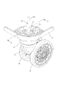
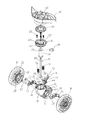
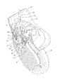
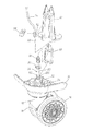
図1乃至図5を参照する。本考案の第一実施例によれば、ホイールキャリヤ10と少なくとも一つの第一中空スリーブ12、連動器14、ホイールキャリヤディスク16、少なくとも一つのホイール18、少なくとも一つの制動リング20、少なくとも一つの第二中空スリーブ22、少なくとも一つの制動体24、引棒26、軸受28、輪座体30、第三中空スリーブ32及び第一係止リング34が、含有される。
ホイールキャリヤ10の上半部において、頂面に、第一収納槽36と複数の第一固定穴38が形成され、下半部において、少なくとも一つの側面に、少なくとも一つの第二収納槽40が形成され、第一収納槽36が第二収納槽40に連通される。また、ホイールキャリヤの下半部には、更に、二つの第二収納槽40を連通する第一枢着穴42が形成される。
この実施例において、第一中空スリーブ12やホイール18、制動リング20、第二中空スリーブ22、制動体24及び第二収納槽40の数が、ともに、それぞれ、二つであることを、例とする。二つの第二収納槽40が、それぞれ、ホイールキャリヤ10の下半部の相対両側に位置し、二つの第二収納槽40に、それぞれ、二つの第一中空スリーブ12が設置される。連動器14は、第二収納槽40に対応するように、第一収納槽36に設置される。連動器14は、第二収納槽40に対応するように、第二枢着穴44が形成される。
Please refer to FIG. 1 to FIG. According to the first embodiment of the present invention, the wheel carrier 10 and at least one first hollow sleeve 12, the interlock 14, the wheel carrier disk 16, at least one wheel 18, at least one brake ring 20, at least one first Two hollow sleeves 22, at least one braking body 24, pull rod 26, bearing 28, wheel seat body 30, third hollow sleeve 32 and first locking ring 34 are contained.
In the upper half of the wheel carrier 10, a first storage tank 36 and a plurality of first fixing holes 38 are formed on the top surface, and in the lower half, at least one second storage tank 40 is formed on at least one side surface. The first storage tank 36 is formed and communicated with the second storage tank 40. The lower half of the wheel carrier is further formed with a first pivot hole 42 that communicates the two second storage tanks 40.
In this embodiment, the number of the first hollow sleeve 12, the wheel 18, the brake ring 20, the second hollow sleeve 22, the brake body 24, and the second storage tank 40 are both two. To do. Two second storage tanks 40 are respectively positioned on opposite sides of the lower half of the wheel carrier 10, and two first hollow sleeves 12 are respectively installed in the two second storage tanks 40. The interlock device 14 is installed in the first storage tank 36 so as to correspond to the second storage tank 40. The interlock device 14 is formed with a second pivot hole 44 so as to correspond to the second storage tank 40.

ホイールキャリヤディスク16は、中央に第一定位穴46が形成され、その第一定位穴46の周りに、更に、複数の第二固定穴48が形成され、複数の固定部材50が、それぞれ、第二固定穴48に貫設されて、第一固定穴38に固定され、これにより、ホイールキャリヤディスク16がホイールキャリヤ10に固定される。
この実施例において、固定部材50は、ネジを例とし、第一固定穴38と第二固定穴48は、ネジ穴を例とする。ホイールキャリヤディスク16は、頂部に、第一定位穴46の周りを囲むリング凹槽52があり、第二固定穴48が、リング凹槽52の底部に貫設されて、それぞれ、固定部材50が貫設される。連動器14は、少なくとも一つの弾性体54で、例えば、ばねであり、上記弾性体54は、ホイールキャリヤディスク16と連動器14との間に位置して、ホイールキャリヤディスク16を付勢する。この実施例において、弾性体54の数は、二つを例とする。
The wheel carrier disk 16 has a first fixed hole 46 formed in the center, and a plurality of second fixing holes 48 are formed around the first fixed hole 46, and the plurality of fixing members 50 are respectively connected to the first fixed hole 46. The two fixing holes 48 are penetrated and fixed to the first fixing hole 38, whereby the wheel carrier disk 16 is fixed to the wheel carrier 10.
In this embodiment, the fixing member 50 is a screw, and the first fixing hole 38 and the second fixing hole 48 are screw holes. The wheel carrier disk 16 has a ring concave tank 52 surrounding the first fixed hole 46 at the top, and a second fixing hole 48 is provided through the bottom of the ring concave tank 52 so that the fixing member 50 is provided. It will be installed. The interlock 14 is at least one elastic body 54, for example, a spring, and the elastic body 54 is located between the wheel carrier disk 16 and the interlock 14 and biases the wheel carrier disk 16. In this embodiment, the number of elastic bodies 54 is two.

各ホイール18は、同軸に、制動リング20と第二中空スリーブ22が固定され、第二中空スリーブ22が、制動リング20の内側に位置する。二つの第一中空スリーブ12には、それぞれ、二つの第二中空スリーブ22が枢着されて、二つのホイール18は、それぞれ、二つの第二収納槽40に設置されて、二つの制動リング20が、それぞれ、二つの第二収納槽40に設置され、また、二つの第二中空スリーブ22が、それぞれ、二つの第二収納槽40に設置される。ホイール18は、第一中空スリーブ12と第二中空スリーブ22を利用して、ホイールキャリヤ10に対して、相対的に回転できる。   Each wheel 18 is coaxially fixed with a brake ring 20 and a second hollow sleeve 22, and the second hollow sleeve 22 is positioned inside the brake ring 20. Two second hollow sleeves 22 are pivotally attached to the two first hollow sleeves 12, and the two wheels 18 are respectively installed in the two second storage tanks 40, and the two brake rings 20. Are installed in the two second storage tanks 40, respectively, and the two second hollow sleeves 22 are installed in the two second storage tanks 40, respectively. The wheel 18 can rotate relative to the wheel carrier 10 using the first hollow sleeve 12 and the second hollow sleeve 22.

二つの制動体24は、それぞれ、二つの第二収納槽40に位置し、制動体24が、第一中空スリーブ12と第二中空スリーブ22と位置ずれに、制動リング20に対応して、ホイールキャリヤ10とホイール18との間に設置される。各制動体24には、更に、第三枢着穴56と第四枢着穴58とが形成され、第一枢着軸60が、第一枢着穴42と二つの第三枢着穴56に貫設されて、二つの制動体24とホイールキャリヤ10を枢着し、第二枢着軸62が、第二枢着穴44と二つの第四枢着穴58に貫設されて、二つの制動体24と連動器14を枢着する。各制動リング20と各制動体24は、それぞれ、第一制動面と第二制動面を有し、上記第一制動面が、上記第二制動面に対面する。この実施例において、第一制動面と第二制動面は、ともに、フェースギヤを例とする。   The two brake bodies 24 are respectively located in the two second storage tanks 40, and the brake bodies 24 are displaced from the first hollow sleeve 12 and the second hollow sleeve 22 to correspond to the brake ring 20, and the wheel. It is installed between the carrier 10 and the wheel 18. Each brake body 24 is further formed with a third pivot hole 56 and a fourth pivot hole 58, and the first pivot shaft 60 is connected to the first pivot hole 42 and the two third pivot holes 56. And the two brake bodies 24 and the wheel carrier 10 are pivotally mounted, and the second pivot shaft 62 is penetrated into the second pivot hole 44 and the two fourth pivot holes 58. The two brake bodies 24 and the interlocking device 14 are pivotally attached. Each brake ring 20 and each brake body 24 have a first brake surface and a second brake surface, respectively, and the first brake surface faces the second brake surface. In this embodiment, the first braking surface and the second braking surface are both face gears.

引棒26は、第一定位穴46に挿設され、一端が、連動器14に固定されて、連動器14を連動し、二つの制動体24を、それぞれ、二つの制動リング20へ向かって移動させるように制御し、同時に、連動器14が連動されて弾性体54を圧縮し、制動体24と制動リング20が、第一制動面と第二制動面で接触する時、制動体24によって、制動リング20とホイール18との回転を防止し、これにより、ホイール18の停止や減速が実現される。   The pulling rod 26 is inserted into the first fixed hole 46, and one end thereof is fixed to the interlocking device 14. The interlocking device 14 is interlocked, and the two braking bodies 24 are moved toward the two braking rings 20, respectively. At the same time, the interlocking unit 14 is interlocked to compress the elastic body 54, and when the braking body 24 and the braking ring 20 come into contact with the first braking surface and the second braking surface, the braking body 24 The rotation of the brake ring 20 and the wheel 18 is prevented, whereby the wheel 18 is stopped or decelerated.

リング凹槽52に、軸受28が収納され、輪座体30が、ホイールキャリヤディスク16に枢設されて、軸受28に実装され、輪座体30において、中央に、第二定位穴64が形成される。輪座体30が、各種類の装置に結合されて、例えば、旅行かばんに結合され、これにより、当該装置は、移動機能が付与される。第三中空スリーブ32は、外表面に、第一リング溝66が形成され、第三中空スリーブ32が、第一リング溝66から露出するように、第一定位穴46と第二定位穴64に貫設され、また、引棒26が、第三中空スリーブ32から露出するように、第三中空スリーブ32に貫設される。第一係止リング34が、輪座体30に密着するように、第一リング溝66に設置されて、第三中空スリーブ32を、第一定位穴46と第二定位穴64に固定する。   The bearing 28 is accommodated in the ring concave tank 52, and the wheel seat 30 is pivotally mounted on the wheel carrier disk 16 and mounted on the bearing 28. In the wheel seat 30, a second localization hole 64 is formed at the center. Is done. The wheel seat body 30 is coupled to each type of device, for example, a travel bag, whereby the device is provided with a moving function. The third hollow sleeve 32 has a first ring groove 66 formed on the outer surface thereof, and the third fixed sleeve 46 and the second fixed hole 64 are formed so that the third hollow sleeve 32 is exposed from the first ring groove 66. The pulling rod 26 is penetrated through the third hollow sleeve 32 so as to be exposed from the third hollow sleeve 32. The first locking ring 34 is installed in the first ring groove 66 so as to be in close contact with the wheel seat body 30, and the third hollow sleeve 32 is fixed to the first fixed hole 46 and the second fixed hole 64.

連動器14は、更に、実装ブロック68と移動ストッパー70及び少なくとも一つの柱体72を有する。この実施例において、柱体72の数は、二つを例とする。実装ブロック68は、第一収納槽36に位置し、第二枢着穴44が形成され、側面に、凹み74があって、第二枢着軸62によって、実装ブロック68と制動体24が、枢着される。
移動ストッパー70は、実装ブロック68上に設置されるように、第一収納槽36に位置し、側面に、凹み74に連通する欠け口76が形成される。移動ストッパー70は、引棒26の一端を、凹み74に固定し、引棒26が、第一収納槽36から露出するように、欠け口76に貫設される。柱体72は、移動ストッパー70上に設置されるように、第一収納槽36に位置し、二つの柱体72に、それぞれ、二つの弾性体54が嵌設され、弾性体54が、ホイールキャリヤディスク16と移動ストッパー70との間において、付勢する。また、引棒26は、更に、棒頭78と棒体80を有する。棒頭78が、凹み74に固定され、棒体80は、一端に、棒頭78が連結されて、欠け口76と第一定位穴46及び第三中空スリーブ32に貫設され、また、第三中空スリーブ32から露出する。
The interlock device 14 further includes a mounting block 68, a movement stopper 70, and at least one column body 72. In this embodiment, the number of column bodies 72 is two. The mounting block 68 is located in the first storage tank 36, the second pivot attachment hole 44 is formed, the side surface has a recess 74, and the second pivot attachment shaft 62 allows the mounting block 68 and the braking body 24 to be connected to each other. It is pivotally attached.
The movement stopper 70 is positioned in the first storage tank 36 so as to be installed on the mounting block 68, and a notch 76 communicating with the recess 74 is formed on the side surface. The moving stopper 70 fixes one end of the pulling rod 26 to the recess 74, and penetrates the chip 76 so that the pulling rod 26 is exposed from the first storage tank 36. The column body 72 is positioned in the first storage tank 36 so as to be installed on the movement stopper 70, and two elastic bodies 54 are fitted into the two column bodies 72, respectively. A bias is applied between the carrier disk 16 and the movement stopper 70. The pulling rod 26 further has a rod head 78 and a rod body 80. The rod head 78 is fixed to the recess 74, and the rod body 80 is connected to the rod head 78 at one end, penetrates the notch 76, the first fixed hole 46 and the third hollow sleeve 32, and The three hollow sleeves 32 are exposed.

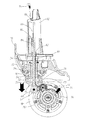
以下、本考案の第一実施例の作動を説明する。引棒26は、上へ引かれていない場合、実装ブロック68が、第一収納槽36のもっとも底部に位置する。そのため、制動体24と制動リング20とが、互いに接触せず、この時、ホイール18が、第一中空スリーブ12と第二中空スリーブ22により、ホイールキャリヤ10に対して、相対的に回転できる。引棒26が、上へ引かれた場合、引棒26によって、実装ブロック68と移動ストッパー70とが、連動されて、弾性体54を圧縮し、同時に、実装ブロック68によって制動体24が連動され、第一枢着軸60を軸方向として、制動リング20が回転できる。制動リング20の第一制動面と制動体24の第二制動面とが、接触して摩擦する時、制動体24により、制動リング20とホイール18の回転が止められる。   The operation of the first embodiment of the present invention will be described below. When the pulling rod 26 is not pulled upward, the mounting block 68 is positioned at the bottom of the first storage tank 36. Therefore, the brake body 24 and the brake ring 20 do not contact each other, and at this time, the wheel 18 can rotate relative to the wheel carrier 10 by the first hollow sleeve 12 and the second hollow sleeve 22. When the pull rod 26 is pulled upward, the mounting block 68 and the movement stopper 70 are interlocked by the pull rod 26 to compress the elastic body 54, and at the same time, the braking body 24 is interlocked by the mounting block 68. The brake ring 20 can rotate with the first pivot shaft 60 as the axial direction. When the first braking surface of the braking ring 20 and the second braking surface of the braking body 24 come into contact and rub, the braking body 24 stops the rotation of the braking ring 20 and the wheel 18.

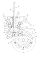
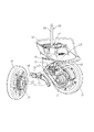
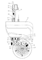
図3や図6乃至図8を参照する。本考案の第二実施例によれば、第一実施例に示された素子の他に、更に、第四中空スリーブ82や第二係止リング84、ばね86、連動ケーシング88、引き紐90、保護ケーシング92、紐体94、固定構造96及び固定板98を有する。
引棒26の棒体80は、第三中空スリーブ32から露出するように、第四中空スリーブ82に貫設される。第四中空スリーブ82は、第三中空スリーブ32の上方に位置して、引棒26の棒体80上を摺動し、外表面に、第二リング溝100が形成される。第二係止リング84は、第四中空スリーブ82の上方に位置するように、棒体80に係止する。ばね86は、棒体80に嵌設され、一端が、第二係止リング84に固定され、もう一端が、第二係止リング84と第四中空スリーブ82との間に位置する。
連動ケーシング88は、輪座体30の上方に位置するように、第二リング溝100に固定されて、ばね86と第二係止リング84を覆う。引き紐90は、一端が、連動ケーシング88に固定され、連動ケーシング88と第四中空スリーブ82が、連動されてばね86を圧縮し、そして、順に、第二係止リング84引棒26とが、連動される。保護ケーシング92は、連動ケーシング88を覆って、連動ケーシング88が、保護ケーシング92上を移動する。紐体94は、固定構造96によって引き紐90が連接され、固定構造96は、固定板98によって、保護ケーシング92に固定される。
Please refer to FIG. 3 and FIGS. According to the second embodiment of the present invention, in addition to the elements shown in the first embodiment, the fourth hollow sleeve 82, the second locking ring 84, the spring 86, the interlocking casing 88, the pull string 90, A protective casing 92, a string 94, a fixing structure 96, and a fixing plate 98 are provided.
The rod body 80 of the pulling rod 26 is penetrated through the fourth hollow sleeve 82 so as to be exposed from the third hollow sleeve 32. The fourth hollow sleeve 82 is positioned above the third hollow sleeve 32 and slides on the rod body 80 of the pulling rod 26, and the second ring groove 100 is formed on the outer surface. The second locking ring 84 is locked to the rod body 80 so as to be positioned above the fourth hollow sleeve 82. The spring 86 is fitted to the rod body 80, one end is fixed to the second locking ring 84, and the other end is located between the second locking ring 84 and the fourth hollow sleeve 82.
The interlocking casing 88 is fixed to the second ring groove 100 so as to be positioned above the wheel seat body 30 and covers the spring 86 and the second locking ring 84. One end of the pull cord 90 is fixed to the interlocking casing 88, the interlocking casing 88 and the fourth hollow sleeve 82 are interlocked to compress the spring 86, and, in turn, the second locking ring 84 and the pulling rod 26. , Interlocked. The protective casing 92 covers the interlocking casing 88, and the interlocking casing 88 moves on the protective casing 92. The string 94 is connected to the pulling string 90 by a fixing structure 96, and the fixing structure 96 is fixed to the protective casing 92 by a fixing plate 98.

以下、本考案の第二実施例の作動を説明する。引棒26は、上へ引かれていない場合、実装ブロック68が、第一収納槽36のもっとも底部に位置し、そのため、制動体24と制動リング20とが、互いに接触しない。この時、ホイール18が、第一中空スリーブ12と第二中空スリーブ22により、ホイールキャリヤ10に対して、相対的に回転できる。
紐体94が、上へ引かれた場合、紐体94により、順に、引き紐90や連動ケーシング88及び第四中空スリーブ82が連動され、これにより、第四中空スリーブ82が、ばね86を圧縮して、更に、順に、第二係止リング84と引棒26が上へ移動するように、連動させる。そのため、引棒26により、実装ブロック68と移動ストッパー70が、弾性体54を圧縮するように、連動され、同時に、実装ブロック68により、制動体24が連動されて、第一枢着軸60を軸方向として制動リング20が回転する。制動リング20の第一制動面と制動体24の第二制動面とが、接触して摩擦する時、制動体24により、制動リング20とホイール18の回転が止められる。
第二実施例において、第一制動面と第二制動面とは、フェースギヤを例とするため、二つのフェースギヤが摩擦接触する時、ホイール18が、回転すれば制動体24が、第一枢着軸60と軸方向として、制動リング20の逆方向へ回転し、そのため、衝撃力により、引棒26と第二係止リング84とが、一瞬に下へ移動し、この時、ばね86により、その衝撃力が減衰される。
The operation of the second embodiment of the present invention will be described below. When the pulling rod 26 is not pulled upward, the mounting block 68 is positioned at the bottom of the first storage tank 36, so that the brake body 24 and the brake ring 20 do not contact each other. At this time, the wheel 18 can rotate relative to the wheel carrier 10 by the first hollow sleeve 12 and the second hollow sleeve 22.
When the string body 94 is pulled upward, the draw string 90, the interlocking casing 88, and the fourth hollow sleeve 82 are sequentially interlocked by the string body 94, whereby the fourth hollow sleeve 82 compresses the spring 86. Further, the second locking ring 84 and the pulling rod 26 are interlocked so as to move upward in order. Therefore, the mounting block 68 and the movement stopper 70 are interlocked so as to compress the elastic body 54 by the pulling rod 26, and at the same time, the braking body 24 is interlocked by the mounting block 68 and the first pivot shaft 60 is moved. The braking ring 20 rotates in the axial direction. When the first braking surface of the braking ring 20 and the second braking surface of the braking body 24 come into contact and rub, the braking body 24 stops the rotation of the braking ring 20 and the wheel 18.
In the second embodiment, since the first braking surface and the second braking surface are face gears, for example, when the two face gears are brought into frictional contact, if the wheel 18 rotates, the braking body 24 is As a result, the pulling rod 26 and the second locking ring 84 are instantaneously moved downward due to the impact force, and the spring 86 is moved downward. Thus, the impact force is attenuated.

以上のように、本考案は、引棒を、連動器を介して制動体に実装することにより、引棒を上へ引く時、制動体を操作してホイールの摺動を止め、ホイールの回転を止めたり減速する目的が実現される。   As described above, according to the present invention, the pull rod is mounted on the brake body via the interlock so that when the pull rod is pulled upward, the brake body is operated to stop the wheel from sliding. The purpose of stopping or slowing down is realized.

そのため、本考案は、より進歩的かつより実用的であり、法に従って実用新案登録請求を出願する。   Therefore, the present invention is more progressive and more practical, and filed a utility model registration request in accordance with the law.

以上は、本考案のより良い実施例にすぎず、本考案がそれによって制限されることは無く、本考案に係る請求の範囲や明細書の内容に基づいて行った等価の変更や修正は、全てが本考案の請求の範囲内に含まれる。   The above is only a better embodiment of the present invention, the present invention is not limited thereby, and equivalent changes and modifications made based on the scope of the claims and the description of the present invention, All are included within the scope of the claims of the present invention.

10 ホイールキャリヤ
100 第二リング溝
12 第一中空スリーブ
14 連動器
16 ホイールキャリヤディスク
18 ホイール
20 制動リング
22 第二中空スリーブ
24 制動体
26 引棒
28 軸受
30 輪座体
32 第三中空スリーブ
34 第一係止リング
36 第一収納槽
38 第一固定穴
40 第二収納槽
42 第一枢着穴
44 第二枢着穴
46 第一定位穴
48 第二固定穴
50 固定部材
52 リング凹槽
54 弾性体
56 第三枢着穴
58 第四枢着穴
60 第一枢着軸
62 第二枢着軸
64 第二定位穴
66 第一リング溝
68 実装ブロック
70 移動ストッパー
72 柱体
74 凹み
76 欠け口
78 棒頭
80 棒体
82 第四中空スリーブ
84 第二係止リング
86 ばね
88 連動ケーシング
90 引き紐
92 保護ケーシング
94 紐体
96 固定構造
98 固定板
10 wheel carrier 100 second ring groove 12 first hollow sleeve 14 interlock 16 wheel carrier disk 18 wheel 20 brake ring 22 second hollow sleeve 24 brake body 26 pull rod 28 bearing 30 wheel seat body 32 third hollow sleeve 34 first Locking ring 36 First storage tank 38 First fixing hole 40 Second storage tank 42 First pivot mounting hole 44 Second pivot mounting hole 46 First fixed hole 48 Second fixing hole 50 Fixing member 52 Ring concave tank 54 Elastic body 56 Third pivot mounting hole 58 Fourth pivot mounting hole 60 First pivot mounting shaft 62 Second pivot mounting shaft 64 Second positioning hole 66 First ring groove 68 Mounting block 70 Moving stopper 72 Column body 74 Recess 76 Notch 78 Rod Head 80 Rod 82 Fourth hollow sleeve 84 Second locking ring 86 Spring 88 Interlocking casing 90 Pull string 92 Protective casing 94 String body 96 Fixing structure 98 Fixing plate

Claims (16)

上半部において、頂面に、第一収納槽が形成され、下半部において、少なくとも一つの側面に、少なくとも一つの第二収納槽が形成され、上記第一収納槽が、上記第二収納槽に連通され、上記第二収納槽に、第一中空スリーブが設置されるホイールキャリヤと、
上記第二収納槽に対応して、上記第一収納槽に設置される連動器と、
同軸に、制動リングと第二中空スリーブとが固定され、上記第二中空スリーブが、上記制動リングの内側に位置し、上記第一中空スリーブが、上記第二中空スリーブに枢着されて、上記制動リングと上記第二中空スリーブと一緒に、上記第二収納槽に設置され、また、上記第一中空スリーブと上記第二中空スリーブにより、上記ホイールキャリヤに対して、相対的に回転する少なくとも一つのホイールと、
上記制動リングに対応して、上記第一中空スリーブと上記第二中空スリーブと位置ずれに、上記ホイールキャリヤと上記ホイールとの間に設置され、第一枢着軸と第二枢着軸によって、それぞれ、上記ホイールキャリヤと上記連動器に枢着される少なくとも一つの制動体と、
その一端が、上記連動器に固定されて、上記連動器が連動され、上記制動体を上記制動リングに向かって移動させるように、制御し、上記制動体と上記制動リングとが、接触する時、上記制動体で、上記制動リングと上記ホイールの回転を止める引棒と、が含有されることを特徴とする、
制動可能な輪座。
In the upper half, a first storage tank is formed on the top surface, and in the lower half, at least one second storage tank is formed on at least one side surface, and the first storage tank is the second storage tank. A wheel carrier that communicates with the tank and in which the first hollow sleeve is installed in the second storage tank;
Corresponding to the second storage tank, the interlock device installed in the first storage tank,
The brake ring and the second hollow sleeve are fixed coaxially, the second hollow sleeve is positioned inside the brake ring, the first hollow sleeve is pivotally attached to the second hollow sleeve, and The brake ring and the second hollow sleeve are installed in the second storage tank, and at least one rotating relative to the wheel carrier by the first hollow sleeve and the second hollow sleeve. With two wheels,
Corresponding to the brake ring, the first hollow sleeve and the second hollow sleeve are displaced between the wheel carrier and the wheel, and the first pivot shaft and the second pivot shaft, Respectively, at least one braking body pivotally attached to the wheel carrier and the interlock;
When one end is fixed to the interlock, the interlock is interlocked, and the brake body is controlled to move toward the brake ring, and the brake body and the brake ring come into contact with each other. The brake member includes the brake ring and a pulling rod for stopping the rotation of the wheel.
Braking wheel seat.
更に、ホイールキャリヤディスクがあり、中央位置に第一定位穴が形成され、上記ホイールキャリヤディスクが、複数の固定部材によって、上記ホイールキャリヤに固定され、上記連動器に、少なくとも、一つの弾性体が設置され、上記弾性体が、上記ホイールキャリヤディスクと上記連動器との間に位置して、上記ホイールキャリヤディスクに付勢し、上記引棒が、上記第一定位穴に挿設されて、上記引棒により、上記連動器が連動されて上記弾性体を圧縮することを特徴とする請求項1に記載の制動可能な輪座。   Further, there is a wheel carrier disk, a first fixed hole is formed at a central position, the wheel carrier disk is fixed to the wheel carrier by a plurality of fixing members, and at least one elastic body is provided in the interlock. Installed, the elastic body is positioned between the wheel carrier disk and the interlock, and urges the wheel carrier disk, and the pull rod is inserted into the first fixed hole, 2. The brakeable wheel seat according to claim 1, wherein the interlocking unit is interlocked by a pull rod to compress the elastic body. 上記ホイールキャリヤの上記頂面に、更に複数の第一固定穴が形成され、上記ホイールキャリヤディスクは、上記第一定位穴の周りに、更に、複数の第二固定穴が形成され、上記固定部材が、それぞれ、上記第二固定穴に貫設されて、それぞれ、上記第一固定穴に固定され、そして、上記ホイールキャリヤディスクを、上記ホイールキャリヤに固定することを特徴とする請求項2に記載の制動可能な輪座。   A plurality of first fixing holes are further formed in the top surface of the wheel carrier, and the wheel carrier disk is further formed with a plurality of second fixing holes around the first fixed hole, and the fixing member. 3, respectively, are inserted into the second fixing holes, respectively fixed to the first fixing holes, and the wheel carrier disk is fixed to the wheel carrier. Brakeable wheel seat. 上記固定部材が、ネジであり、上記第一固定穴と上記第二固定穴が、ネジ穴であることを特徴とする請求項3に記載の制動可能な輪座。   4. The brakeable wheel seat according to claim 3, wherein the fixing member is a screw, and the first fixing hole and the second fixing hole are screw holes. 上記第二収納槽や上記ホイール及び上記制動体の数は、それぞれ、二つであり、上記二つの第二収納槽が、それぞれ、上記ホイールキャリヤの上記下半部の相対両側に位置し、上記二つのホイールが、それぞれ、上記二つの第二収納槽に位置し、上記二つの制動体が、それぞれ、上記二つの第二収納槽に位置し、上記二つのホイールが、それぞれ、同軸に、上記二つの制動リングを固定し、上記二つの制動リングが、それぞれ、上記二つの第二収納槽に位置することを特徴とする請求項2に記載の制動可能な輪座。   The number of the second storage tank, the wheel, and the braking body is two respectively, and the two second storage tanks are respectively positioned on both sides of the lower half of the wheel carrier, and Two wheels are respectively positioned in the two second storage tanks, the two brake bodies are respectively positioned in the two second storage tanks, and the two wheels are coaxially, The brakeable wheel seat according to claim 2, wherein two brake rings are fixed, and the two brake rings are respectively located in the two second storage tanks. 上記ホイールキャリヤは、更に、上記第二収納槽に連通する第一枢着穴が形成され、上記第一枢着軸が、上記第一枢着穴に貫設されて、上記ホイールキャリヤと上記制動体とを枢着することを特徴とする請求項5に記載の制動可能な輪座。   The wheel carrier further includes a first pivot hole that communicates with the second storage tank, and the first pivot axis is inserted into the first pivot hole so that the wheel carrier and the brake are 6. A brakeable wheel seat according to claim 5, wherein the wheel seat is pivotally attached to the body. 上記連動器は、更に、上記第一収納槽に位置し、第二枢着穴が形成され、側面に、凹みが形成され、上記第二枢着穴が、上記第二収納槽に対応するように、位置し、上記第二枢着軸が、上記第二枢着穴に貫設されて、実装ブロックと上記制動体とが枢着される実装ブロックと、上記第一収納槽に位置するように、上記実装ブロック上に設置され、側面に、上記凹みに連通する欠け口が、形成され、上記引棒の上記端が、上記凹みに制限され、上記引棒が、上記欠け口に貫設されて、上記第一収納槽から露出する移動ストッパーと、上記第一収納槽に位置するように、上記移動ストッパー上に設置され、上記弾性体が嵌設され、上記弾性体が、上記ホイールキャリヤディスクと上記移動ストッパーとの間において、付勢する少なくとも一つの柱体と、が含有されることを特徴とする請求項5に記載の制動可能な輪座。   The interlock is further located in the first storage tank, a second pivot hole is formed, a recess is formed in a side surface, and the second pivot hole corresponds to the second storage tank. And the second pivot shaft is inserted into the second pivot hole so that the mount block and the brake member are pivotally mounted on the first storage tank. Further, a notch that is installed on the mounting block and communicates with the recess is formed on a side surface, the end of the pull bar is limited to the recess, and the pull bar penetrates the notch. A movable stopper exposed from the first storage tank; and the movable stopper is disposed on the movable stopper so as to be positioned in the first storage tank; the elastic body is fitted; and the elastic body is the wheel carrier. At least one pillar for biasing between the disc and the moving stopper When braking possible wheel seat according to claim 5, characterized in that is contained. 上記弾性体と上記柱体の数は、それぞれ、二つであり、上記二つの弾性体が、それぞれ、上記二つの柱体に嵌設されることを特徴とする請求項7に記載の制動可能な輪座。   The number of the elastic bodies and the number of the column bodies is two, respectively, and the two elastic bodies are fitted on the two column bodies, respectively. Circle seat. 上記引棒は、更に、上記凹みに固定される棒頭と、その一端が、上記棒頭に連結され、上記欠け口と上記第一定位穴に貫設される棒体と、が含有されることを特徴とする請求項7に記載の制動可能な輪座。   The pull rod further includes a rod head fixed to the recess, and a rod body having one end connected to the rod head and penetrating through the notch and the first fixed hole. A brakeable wheel seat according to claim 7. 上記制動体は、更に、第三枢着穴と第四枢着穴が形成され、上記第一枢着軸が、上記第三枢着穴に貫設されて、上記制動体と上記ホイールキャリヤが枢着され、上記第二枢着軸が、上記第四枢着穴に貫設されて、上記制動体と上記連動器が枢着されることを特徴とする請求項1に記載の制動可能な輪座。   The braking body further includes a third pivot mounting hole and a fourth pivot mounting hole, the first pivot mounting shaft extends through the third pivot mounting hole, and the braking body and the wheel carrier are connected to each other. The brakeable according to claim 1, wherein the second pivot shaft is pivotally mounted, the second pivot shaft is penetrated through the fourth pivot hole, and the brake body and the interlock are pivotally mounted. Circle seat. 上記制動リングと上記制動体は、それぞれ、第一制動面と第二制動面を有し、上記第一制動面が、上記第二制動面に相対することを特徴とする請求項10に記載の制動可能な輪座。   The brake ring and the brake body have a first brake surface and a second brake surface, respectively, and the first brake surface is opposed to the second brake surface. Braking wheel seat. 上記第一制動面と上記第二制動面は、ともに、フェースギヤであることを特徴とする請求項11に記載の制動可能な輪座。   12. The brakeable wheel seat according to claim 11, wherein both the first braking surface and the second braking surface are face gears. 更に、上記ホイールキャリヤディスクの頂部において、上記第一定位穴の周りに形成されたリング状凹槽に位置し、上記固定部材が、上記リング状凹槽に貫設されて、上記ホイールキャリヤディスクと上記ホイールキャリヤを固定する軸受と、上記軸受に位置するように、上記ホイールキャリヤディスクに枢設され、中央に第二定位穴が形成される輪座体と、外表面に、第一リング溝が形成され、上記第一リング溝から露出するように、上記第一定位穴と上記第二定位穴に貫設されて、上記引棒が、露出するように、貫設される第三中空スリーブと、上記輪座体に密着するように、上記第一リング溝に設置されて、上記第三中空スリーブが上記第一定位穴と上記第二定位穴に固定される第一係止リングと、が含有されることを特徴とする請求項2に記載の制動可能な輪座。   Further, at the top of the wheel carrier disk, it is located in a ring-shaped concave tank formed around the first fixed hole, and the fixing member penetrates the ring-shaped concave tank, A bearing for fixing the wheel carrier, a wheel seat body pivoted on the wheel carrier disk so as to be positioned on the bearing, and a second positioning hole formed in the center, and a first ring groove on the outer surface A third hollow sleeve formed and penetrated through the first fixed hole and the second fixed hole so as to be exposed from the first ring groove, and so as to expose the pull rod; A first locking ring that is installed in the first ring groove so as to be in close contact with the wheel seat body, and the third hollow sleeve is fixed to the first fixed hole and the second fixed hole. Claim characterized by being contained Braking possible wheel seat described in 2. 更に、上記引棒が、上記第三中空スリーブから露出するように、貫設され、上記第三中空スリーブの上方に位置して、上記引棒を摺動し、また、外表面に、第二リング溝が形成される第四中空スリーブと、上記第四中空スリーブの上方に位置するように、上記引棒に係止される第二係止リングと、上記引棒に嵌設され、一端が、上記第二係止リングに固定され、もう一端が、上記第二係止リングと上記第四中空スリーブとの間に位置するばねと、上記第二リング溝に固定されるように、上記輪座体の上方に設置されて、上記ばねと上記第二係止リングを覆う連動ケーシングと、一端が上記連動ケーシングに固定されて、上記連動ケーシングと上記第四中空スリーブが固定されて上記ばねを圧縮し、順に上記第二係止リングと上記引棒とが連動される引き紐と、が含有されることを特徴とする請求項13に記載の制動可能な輪座。   Further, the pulling rod is provided so as to be exposed from the third hollow sleeve, and is positioned above the third hollow sleeve to slide the pulling rod. A fourth hollow sleeve in which a ring groove is formed; a second locking ring that is locked to the pulling bar so as to be positioned above the fourth hollow sleeve; The wheel is fixed to the second locking ring, and the other end is fixed to the second ring groove and a spring positioned between the second locking ring and the fourth hollow sleeve. An interlocking casing that is installed above the seat and covers the spring and the second locking ring, one end is fixed to the interlocking casing, and the interlocking casing and the fourth hollow sleeve are fixed to fix the spring. Compress and interlock the second locking ring and the pull rod in order Braking possible wheel seat according to claim 13 in which the drawstring to be, is characterized in that it is contained. 更に、上記連動ケーシングを覆い、上記連動ケーシングが、上において移動する保護ケーシングと、固定構造によって上記引き紐に連接され、上記固定構造が、固定板によって、上記保護ケーシングに固定される紐体と、が含有されることを特徴とする請求項14に記載の制動可能な輪座。   Furthermore, the interlocking casing covers the interlocking casing, the interlocking casing is moved upward, and the strap is connected to the drawstring by a fixing structure, and the fixing structure is fixed to the protection casing by a fixing plate; A brakeable wheel seat according to claim 14, characterized in that 上記弾性体は、ばねであることを特徴とする請求項2に記載の制動可能な輪座。   The brakeable wheel seat according to claim 2, wherein the elastic body is a spring.
JP2015003984U 2015-07-21 2015-08-05 Braking wheel seat Expired - Lifetime JP3200529U (en)

Applications Claiming Priority (2)

Application Number Priority Date Filing Date Title
TW104211710U TWM511239U (en) 2015-07-21 2015-07-21 Brake wheel
TW104211710 2015-07-21

Publications (1)

Publication Number Publication Date
JP3200529U true JP3200529U (en) 2015-10-22

Family

ID=54477559

Family Applications (1)

Application Number Title Priority Date Filing Date
JP2015003984U Expired - Lifetime JP3200529U (en) 2015-07-21 2015-08-05 Braking wheel seat

Country Status (2)

Country Link
JP (1) JP3200529U (en)
TW (1) TWM511239U (en)

Cited By (3)

* Cited by examiner, † Cited by third party
Publication number Priority date Publication date Assignee Title
JP2020059499A (en) * 2019-11-22 2020-04-16 株式会社日乃本錠前 Lock device, caster with brake device, carrier, and object placement tool
JP2021035828A (en) * 2020-10-16 2021-03-04 株式会社日乃本錠前 Caster brake device, caster with brake device, carrier, and object mounter
JP2021037947A (en) * 2020-10-16 2021-03-11 株式会社日乃本錠前 Casters with braking device, conveyance device, and object mounting device

Citations (3)

* Cited by examiner, † Cited by third party
Publication number Priority date Publication date Assignee Title
JPS57194803U (en) * 1981-06-05 1982-12-10
JP3148376U (en) * 2008-11-27 2009-02-12 賀盛塑鋼股▲ふん▼有限公司 Casters used for suitcases
JP3150540U (en) * 2009-03-03 2009-05-21 呉禎權 Casters used for suitcases

Patent Citations (3)

* Cited by examiner, † Cited by third party
Publication number Priority date Publication date Assignee Title
JPS57194803U (en) * 1981-06-05 1982-12-10
JP3148376U (en) * 2008-11-27 2009-02-12 賀盛塑鋼股▲ふん▼有限公司 Casters used for suitcases
JP3150540U (en) * 2009-03-03 2009-05-21 呉禎權 Casters used for suitcases

Cited By (3)

* Cited by examiner, † Cited by third party
Publication number Priority date Publication date Assignee Title
JP2020059499A (en) * 2019-11-22 2020-04-16 株式会社日乃本錠前 Lock device, caster with brake device, carrier, and object placement tool
JP2021035828A (en) * 2020-10-16 2021-03-04 株式会社日乃本錠前 Caster brake device, caster with brake device, carrier, and object mounter
JP2021037947A (en) * 2020-10-16 2021-03-11 株式会社日乃本錠前 Casters with braking device, conveyance device, and object mounting device

Also Published As

Publication number Publication date
TWM511239U (en) 2015-11-01

Similar Documents

Publication Publication Date Title
CN103448781B (en) Brakes and toddler vehicles with brakes
CN100556716C (en) Hubless caster
JP3200529U (en) Braking wheel seat
TWI520869B (en) Brake mechanism for infant stroller
KR102245979B1 (en) Caster and stroller
EP2662262A2 (en) Folding golf cart
CN204378181U (en) The luggage case of automatic walking
CN102715720B (en) suitcase
JP2018128110A (en) Wheel structure and wheelbarrow with the wheel structure
TWI643764B (en) Buffered caster device
CN207565666U (en) The braking mechanism and children trolley of children trolley
JP3185465U (en) Shopping cart with chair function
US20210177113A1 (en) Luggage case for children
CN209359832U (en) A kind of suitcase with universal wheel trolley that can be parked
CN210382967U (en) Suitcase universal wheel with anti-seismic function
CN108715182A (en) Base lock mechanism of stopping
CN206155527U (en) An unlocking mechanism for a stroller
CN203651344U (en) Wheel set structure
JP3161658U (en) Caster structure
CN2391757Y (en) casters
CN203986537U (en) A kind of brake wheel braking mechanism of luggage case
CN208559467U (en) Base lock mechanism of stopping
JP2014195517A (en) Brake operation mechanism for movable table
JP5672601B2 (en) caster
CN204846115U (en) A key triggers formula heel brace mechanism and balance car

Legal Events

Date Code Title Description
R150 Certificate of patent or registration of utility model

Ref document number: 3200529

Country of ref document: JP

Free format text: JAPANESE INTERMEDIATE CODE: R150

A623 Registrability report

Free format text: JAPANESE INTERMEDIATE CODE: A623

Effective date: 20160119

R250 Receipt of annual fees

Free format text: JAPANESE INTERMEDIATE CODE: R250

R250 Receipt of annual fees

Free format text: JAPANESE INTERMEDIATE CODE: R250

R250 Receipt of annual fees

Free format text: JAPANESE INTERMEDIATE CODE: R250

R250 Receipt of annual fees

Free format text: JAPANESE INTERMEDIATE CODE: R250

R250 Receipt of annual fees

Free format text: JAPANESE INTERMEDIATE CODE: R250

R250 Receipt of annual fees

Free format text: JAPANESE INTERMEDIATE CODE: R250

EXPY Cancellation because of completion of term