JP3197651U - Car wheel truck expansion system - Google Patents
Car wheel truck expansion system Download PDFInfo
- Publication number
- JP3197651U JP3197651U JP2015001113U JP2015001113U JP3197651U JP 3197651 U JP3197651 U JP 3197651U JP 2015001113 U JP2015001113 U JP 2015001113U JP 2015001113 U JP2015001113 U JP 2015001113U JP 3197651 U JP3197651 U JP 3197651U
- Authority
- JP
- Japan
- Prior art keywords
- wheel track
- wheel
- centering
- central opening
- track extension
- Prior art date
- Legal status (The legal status is an assumption and is not a legal conclusion. Google has not performed a legal analysis and makes no representation as to the accuracy of the status listed.)
- Active
Links
Images


Classifications
-
- B—PERFORMING OPERATIONS; TRANSPORTING
- B60—VEHICLES IN GENERAL
- B60B—VEHICLE WHEELS; CASTORS; AXLES FOR WHEELS OR CASTORS; INCREASING WHEEL ADHESION
- B60B3/00—Disc wheels, i.e. wheels with load-supporting disc body
- B60B3/14—Attaching disc body to hub ; Wheel adapters
- B60B3/147—Attaching disc body to hub ; Wheel adapters using wheel adapters
-
- B—PERFORMING OPERATIONS; TRANSPORTING
- B60—VEHICLES IN GENERAL
- B60B—VEHICLE WHEELS; CASTORS; AXLES FOR WHEELS OR CASTORS; INCREASING WHEEL ADHESION
- B60B19/00—Wheels not otherwise provided for or having characteristics specified in one of the subgroups of this group
-
- B—PERFORMING OPERATIONS; TRANSPORTING
- B60—VEHICLES IN GENERAL
- B60B—VEHICLE WHEELS; CASTORS; AXLES FOR WHEELS OR CASTORS; INCREASING WHEEL ADHESION
- B60B3/00—Disc wheels, i.e. wheels with load-supporting disc body
- B60B3/14—Attaching disc body to hub ; Wheel adapters
- B60B3/16—Attaching disc body to hub ; Wheel adapters by bolts or the like
-
- B—PERFORMING OPERATIONS; TRANSPORTING
- B60—VEHICLES IN GENERAL
- B60B—VEHICLE WHEELS; CASTORS; AXLES FOR WHEELS OR CASTORS; INCREASING WHEEL ADHESION
- B60B2310/00—Manufacturing methods
- B60B2310/30—Manufacturing methods joining
- B60B2310/306—Manufacturing methods joining by clamping or wedging, e.g. by clamping inserts as joining means
-
- B—PERFORMING OPERATIONS; TRANSPORTING
- B60—VEHICLES IN GENERAL
- B60B—VEHICLE WHEELS; CASTORS; AXLES FOR WHEELS OR CASTORS; INCREASING WHEEL ADHESION
- B60B2360/00—Materials; Physical forms thereof
- B60B2360/30—Synthetic materials
- B60B2360/32—Plastic compositions
-
- B—PERFORMING OPERATIONS; TRANSPORTING
- B60—VEHICLES IN GENERAL
- B60B—VEHICLE WHEELS; CASTORS; AXLES FOR WHEELS OR CASTORS; INCREASING WHEEL ADHESION
- B60B2360/00—Materials; Physical forms thereof
- B60B2360/30—Synthetic materials
- B60B2360/34—Reinforced plastics
- B60B2360/341—Reinforced plastics with fibres
-
- B—PERFORMING OPERATIONS; TRANSPORTING
- B60—VEHICLES IN GENERAL
- B60B—VEHICLE WHEELS; CASTORS; AXLES FOR WHEELS OR CASTORS; INCREASING WHEEL ADHESION
- B60B2900/00—Purpose of invention
- B60B2900/10—Reduction of
- B60B2900/112—Costs
-
- B—PERFORMING OPERATIONS; TRANSPORTING
- B60—VEHICLES IN GENERAL
- B60B—VEHICLE WHEELS; CASTORS; AXLES FOR WHEELS OR CASTORS; INCREASING WHEEL ADHESION
- B60B2900/00—Purpose of invention
- B60B2900/10—Reduction of
- B60B2900/116—Product variety, e.g. by standardisation or use of adapters
-
- B—PERFORMING OPERATIONS; TRANSPORTING
- B60—VEHICLES IN GENERAL
- B60B—VEHICLE WHEELS; CASTORS; AXLES FOR WHEELS OR CASTORS; INCREASING WHEEL ADHESION
- B60B2900/00—Purpose of invention
- B60B2900/30—Increase in
- B60B2900/351—Increase in versatility, e.g. usable for different purposes or different arrangements
-
- B—PERFORMING OPERATIONS; TRANSPORTING
- B60—VEHICLES IN GENERAL
- B60Y—INDEXING SCHEME RELATING TO ASPECTS CROSS-CUTTING VEHICLE TECHNOLOGY
- B60Y2200/00—Type of vehicle
- B60Y2200/10—Road Vehicles
-
- B—PERFORMING OPERATIONS; TRANSPORTING
- B60—VEHICLES IN GENERAL
- B60Y—INDEXING SCHEME RELATING TO ASPECTS CROSS-CUTTING VEHICLE TECHNOLOGY
- B60Y2200/00—Type of vehicle
- B60Y2200/10—Road Vehicles
- B60Y2200/11—Passenger cars; Automobiles
Abstract
【課題】様々なホイールリム及び様々な車両にフレキシブルに使用することができる、自動車のホイールトラック拡張システムを提供する。【解決手段】少なくとも1つのホイールトラック拡張ディスク10とホイールトラック拡張ディスクの中央開口部に挿入される芯合わせリング12とを有する、自動車のホイールトラック拡張システムに関する。芯合わせリングは、プラスチック材料を含み、弾性アーム32の自由端部に配置される少なくとも1つの第1の留め金構造を有し、ホイールトラック拡張ディスクは、対応する第2の留め金構造を有する。【選択図】図1An automotive wheel track expansion system that can be flexibly used in various wheel rims and various vehicles. An automotive wheel track expansion system having at least one wheel track expansion disk and a centering ring inserted into a central opening of the wheel track expansion disk. The centering ring comprises a plastic material and has at least one first clasp structure disposed at the free end of the elastic arm 32, and the wheel track expansion disc has a corresponding second clasp structure. . [Selection] Figure 1
Description
本考案は、少なくとも1つのホイールトラック拡張ディスク又はホイールスペーサディスクを有する、自動車のホイールトラック拡張システム又はホイールスペーサシステムに関する。 The present invention relates to a vehicle wheel track expansion system or wheel spacer system having at least one wheel track expansion disk or wheel spacer disk.
本考案の目的は、様々なホイールリム及び様々な車両にフレキシブルに使用することができる、自動車のホイールトラック(車輪左右間隔)の拡張システムを提供することである。 It is an object of the present invention to provide an expansion system for an automobile wheel track (wheel spacing) that can be flexibly used in various wheel rims and various vehicles.
このために、本考案に従って、請求項1又は請求項8に記載の自動車のホイールトラック拡張システムを提供する。ホイールトラック拡張システムは、少なくとも1つのホイールトラック拡張ディスクとホイールトラック拡張ディスクの中央開口部に挿入される芯合わせリングとを有し、芯合わせリングは、プラスチック材料を含む。特に、芯合わせリングは、弾性アームの自由端部に配置された少なくとも1つの第1の留め金構造を備え、ホイールトラック拡張ディスクは、対応する第2の留め金構造を備える。 To this end, according to the present invention, there is provided a vehicle wheel track expansion system according to claim 1 or claim 8. The wheel track extension system has at least one wheel track extension disk and a centering ring that is inserted into a central opening of the wheel track extension disk, the centering ring comprising a plastic material. In particular, the centering ring comprises at least one first clasp structure arranged at the free end of the elastic arm, and the wheel track expansion disc comprises a corresponding second clasp structure.
ホイールトラック拡張ディスクと、ディスクとは別個の芯合わせリングと、を備えることによって、本考案のホイールトラック拡張システムは、様々な車両及び様々なホイールリムにフレキシブルに適合することができる。すなわち、ホイールトラック拡張ディスクは、車両のホイールボルトにぴったり合わなければならず、芯合わせリングは、ホイールリムの中央開口部の直径に合わなければならないので、ホイールリムを芯合わせリング上に配置すれば、ホイールリムは、ホイールトラック拡張ディスクに対して正確に同心にすることができ、又はホイールハブに対して、又はホイールボルトのピッチ円に対して、同心にすることができるので、簡単に組立てることができる。本考案は、ホイールリムからホイールハブに又はホイールハブからホイールリムに加えられる力及びモーメントは、専らホイールトラック拡張ディスクによって伝達されるので、運転操作中には芯合わせリングに負荷を与えない、という認識に基づいている。従って、ホイールトラック拡張ディスクが取り付けられるときやホイールリムが取り付けられるときに、芯合わせリングは、芯合わせ機能のみを発揮すればよく、芯合わせリングをプラスチック材料で製造することができるという利益を有する。従って、芯合わせリングは、様々な車両及びホイールリムに対して本考案に係るホイールトラック拡張システムを使用できるようにするために、非常にコスト効率よくかつ非常に多様な寸法に製造することができる。芯合わせリングは、例えば、プラスチック射出成形部品として、特に繊維強化プラスチック部品として構成することができ、上述のように、芯合わせリングは、運転操作中一切の負荷を受けない。プラスチック材料、特にプラスチック射出成形材料で芯合わせリングを製造することは、様々な芯合わせリングの製造をより容易にし、様々なホイールリムにホイールトラック拡張ディスクを確実に取り付けることができるようにする。 By including a wheel track extension disk and a centering ring separate from the disk, the wheel track extension system of the present invention can be flexibly adapted to various vehicles and various wheel rims. That is, the wheel track extension disc must fit the vehicle wheel bolt and the centering ring must match the diameter of the central opening of the wheel rim, so the wheel rim should be placed on the centering ring. For example, the wheel rim can be precisely concentric with respect to the wheel track extension disc, or can be concentric with respect to the wheel hub or with respect to the pitch circle of the wheel bolt, so that it is easy to assemble. be able to. According to the present invention, the forces and moments applied from the wheel rim to the wheel hub or from the wheel hub to the wheel rim are transmitted exclusively by the wheel track expansion disk, so that no load is applied to the centering ring during driving operation. Based on recognition. Therefore, when the wheel track extension disk is attached or when the wheel rim is attached, the centering ring only needs to exhibit the centering function, and has the advantage that the centering ring can be made of a plastic material. . Thus, the centering ring can be manufactured in a very cost-effective and very diverse dimension in order to be able to use the wheel track expansion system according to the invention for various vehicles and wheel rims. . The centering ring can be configured, for example, as a plastic injection molded part, in particular as a fiber reinforced plastic part, and as described above, the centering ring is not subjected to any load during the operation. Manufacturing the centering ring from a plastic material, particularly a plastic injection molding material, makes it easier to manufacture the various centering rings and ensures that the wheel track expansion disc can be securely attached to the various wheel rims.
本考案の形態において、第1の留め金構造は、半径方向外向きに突出す、留め金の突出部の形式である。従って、留め金の突出部は、プラスチック構成部品特にプラスチック射出成形構成部品上に簡単に製造できる弾性アームの自由端部に在る。この事例において、重要な点は、この場合にも、芯合わせリングが運転操作中一切の負荷を受けず、従って、弾性アームの自由端部の留め金の突出部が、単にホイールトラック拡張ディスク及びホイールリムがホイールハブに取り付けられたとき生じる力を引き受けるだけであることを、認識することである。自由端部に留め金の突出部を有する複数の、特に4つの弾性アームが、芯合わせリングに設置されると有利である。 In a form of the invention, the first clasp structure is in the form of a clasp projection that projects radially outward. Thus, the clasp protrusion is at the free end of the elastic arm which can be easily manufactured on plastic components, in particular plastic injection molded components. In this case, the important point is that, again, the centering ring is not subjected to any load during operation, so that the protrusion of the clasp at the free end of the elastic arm is simply a wheel track extension disk and Recognize that the wheel rim only takes on the forces that occur when attached to the wheel hub. It is advantageous if a plurality, in particular four elastic arms with clasp projections at the free end are installed on the centering ring.
本考案の形態において、第2の留め金構造は、中央開口部の周上に延びる肩部、中央開口部の周上に延びる面取り部、又は中央開口部の周上に延びる溝によって構成される。 In the form of the present invention, the second clasp structure is constituted by a shoulder portion extending on the circumference of the central opening, a chamfer portion extending on the circumference of the central opening, or a groove extending on the circumference of the central opening. .
周上の肩部、周上の面取り部、又は周上の溝は、ホイールトラック拡張ディスクに容易に設置することができる。なぜなら、ホイールトラック拡張ディスクは、通常、金属であり、いずれにせよ機械加工をしなければならないからである。従って、周上の肩部、周上の面取り部又は周上の溝は、例えば旋盤加工時に、ホイールトラック拡張ディスクに形成することができる。芯合わせリングから突出した、留め金の突出部は、芯合わせリングが挿入されたとき、自動的に、ホイールトラック拡張ディスクの中央開口部に係合する。厚いホイールトラック拡張ディスクの場合、溝は、中央開口部の内壁に設置でき、比較的薄いホイールトラック拡張ディスクの場合、芯合わせリングの留め金の突出部は、ホイールトラック拡張ディスクの中央開口部と上面及び/又は下面との間の移行部に配置された、周上の肩部又は周上の面取り部において係合することができる。 A shoulder on the circumference, a chamfer on the circumference, or a groove on the circumference can be easily installed on the wheel track expansion disc. This is because wheel track expansion discs are usually metal and must be machined anyway. Accordingly, the shoulder on the periphery, the chamfered portion on the periphery, or the groove on the periphery can be formed in the wheel track expansion disk, for example, when turning. The projection of the clasp protruding from the centering ring automatically engages the central opening of the wheel track expansion disc when the centering ring is inserted. For thick wheel track extension discs, the groove can be installed on the inner wall of the central opening, and for relatively thin wheel track extension discs, the protrusions of the centering ring clasps are in contact with the central opening of the wheel track extension disc. It is possible to engage at a shoulder on the circumference or a chamfer on the circumference, arranged at the transition between the upper and / or lower surface.
本考案の形態において、ホイールトラック拡張ディスクは、ホイールボルト穴として周方向に延びる少なくとも1つの湾曲スロットを有する。 In a form of the invention, the wheel track extension disk has at least one curved slot extending circumferentially as a wheel bolt hole.
このようにして、様々な穴の形態を1つのホイールトラック拡張ディスクでカバーすることができる。このようにして、様々な車両及びホイールリムをカバーするために本考案に係るホイールトラック拡張システムが必要とする個別の構成部品の数を減少させることができる。 In this way, various hole configurations can be covered with a single wheel track expansion disc. In this way, the number of individual components required by the wheel track expansion system according to the present invention to cover various vehicles and wheel rims can be reduced.
本考案の形態において、ホイールトラック拡張ディスクは、ホイールボルトを挿入するために設置される複数のホイールボルト穴を有し、ホイールトラック拡張ディスクの半径方向におけるホイールボルト穴の寸法は、ホイールボルトの1.2倍〜1.7倍、特に1.5倍である。 In the form of the present invention, the wheel track extension disk has a plurality of wheel bolt holes installed for inserting the wheel bolts, and the dimension of the wheel bolt hole in the radial direction of the wheel track extension disk is one of the wheel bolts. .2 times to 1.7 times, especially 1.5 times.
様々な車両の様々なピッチ円を、ホイールトラック拡張ディスクのこのような形態によってカバーできる。それによって、様々な車両のために必要な異なるホイールトラック拡張ディスクの数を実質的に減少させることができる。 Different pitch circles of different vehicles can be covered by this form of wheel track expansion disc. Thereby, the number of different wheel track extension disks required for various vehicles can be substantially reduced.
本考案の形態において、相互に異なる複数の芯合わせリングが、本考案に係るホイールトラック拡張システムに提供される。各芯合わせリングは、少なくとも第1の留め金構造によってホイールトラック拡張ディスクに固定するための保持部と、ホイールリムの中央開口部に配置するための芯合わせ部と、を有し、全ての芯合わせリングは、保持部において同じ外径を有し、各芯合わせリングは、芯合わせ部の外径に関して、少なくとも部分的には相互に異なる。 In the form of the present invention, a plurality of different centering rings are provided in the wheel track expansion system according to the present invention. Each centering ring has a holding part for fixing to the wheel track extension disk by at least a first clasp structure, and a centering part for positioning in the central opening of the wheel rim, The alignment rings have the same outer diameter at the holding portion, and each centering ring is at least partially different from one another with respect to the outer diameter of the alignment portion.
このようにして、相互に異なる全ての芯合わせリングを、本考案に係るホイールトラック拡張システムの全てのホイールトラック拡張ディスクに嵌合できるようにすることができる。既述のように、対応する第2の留め金構造も、全ての芯合わせリングが係合することができるように、常に、同様に、相互に異なるホイールトラック拡張ディスクに配置される。 In this way, all different centering rings can be fitted to all wheel track extension disks of the wheel track extension system according to the invention. As already mentioned, the corresponding second clasp structure is also always arranged on different wheel track expansion disks in a similar manner so that all the centering rings can be engaged.
本考案において、更に、異なる厚みのホイールトラック拡張ディスクが提供される。 In the present invention, a different thickness wheel track expansion disk is also provided.
本考案において、更に、異なる配置のホイールボルト穴を有するホイールトラック拡張ディスクが提供される。 In the present invention, there is further provided a wheel track expansion disk having differently arranged wheel bolt holes.
従って、本考案に係るホイールトラック拡張システムは、様々な車両及びホイールリムをカバーすることができるために、様々なホイールトラック拡張ディスク及び様々な芯合わせリングを必要とするが、個々の構成部品の必要数、特に、異なるホイールトラック拡張ディスクの数を、実質的に減少させることができる。異なるホイールトラック拡張ディスクは、例えば、ホイールトラック拡張に対して異なる寸法を与える場合にのみ、必要である。 Thus, the wheel track expansion system according to the present invention requires various wheel track expansion discs and various centering rings in order to be able to cover various vehicles and wheel rims. The required number, in particular the number of different wheel track extension disks, can be substantially reduced. Different wheel track extension disks are only needed, for example, to give different dimensions for wheel track extensions.
本考案の更なる特徴及び利益は、請求項、及び、本考案の好ましい実施形態の以下の説明を、図面とともに参照することにより理解されるであろう。図示され及び/又は図面で説明された、異なる実施形態の個々の特徴は、本考案の範囲を逸脱することなく自由に相互に組み合わせることができる。 Additional features and benefits of the present invention will be understood by reference to the claims and the following description of preferred embodiments of the invention in conjunction with the drawings. The individual features of the different embodiments illustrated and / or illustrated in the drawings can be freely combined with one another without departing from the scope of the invention.
図1は、本考案に係るホイールトラック拡張システムの芯合わせリング12を有するホイールトラック拡張ディスク10を示す。ホイールトラック拡張ディスク10は、合計6つのホイールボルト穴14、16、18、20、22及び24を有する。ホイールボルト穴16、18、20及び24は、円形穴として構成されるのに対して、ホイールボルト穴14及び22は、ホイールトラック拡張ディスク10の周方向に延びるスロットとして構成される。通常、自動車のホイールハブは、4つ又は5つのホイールボルトを備える。従って、ホイールボルト穴14〜24は、ホイールボルトの挿入のために同時に全てが使用されるわけではなく、ホイールハブの様々な穴形態を、1つのホイールトラック拡張ディスク10でカバーすることができるように、配置されている。丸く湾曲する2つのスロット14、22も、このために使用される。更に、円形ホイールボルト穴16、18、20、24の直径、及びホイールボルト穴14、22の寸法は、半径方向に見たとき、使用されるホイールボルトの外径の1.5倍である。異なる車両におけるホイールボルトの多少異なるピッチ円直径は、これによってカバーすることができる。
FIG. 1 shows a wheel
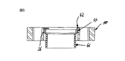
図1の、ホイールトラック拡張ディスク10の後面から見たときの、芯合わせリング12は、ディスクに挿入され、周上の面取りカラー26を有しており、面取りカラー26は、ホイールトラック拡張ディスク10上の芯合わせリング12の端位置を、軸方向において画定する。カラー26が、ホイールトラック拡張ディスク10の後面の中央穴30への移行部における対応する面取り部28に対して当接していることが、図2の断面図に、明確に示されている。ホイールトラック拡張ディスク10の後面は、図2において、上側である。
The centering
芯合わせリング12は、合計4つの弾性アーム32を有し、その自由端部に、それぞれ留め金の突出部34が配置されている。図1には、弾性アーム32と留め金の突出部34とが、2つだけ示されている。留め金の突出部34は、ホイールトラック拡張ディスク10の中央開口部から半径方向外向きに延びる溝36に係合する。その結果、芯合わせリング12は、面取りカラー26がホイールトラック拡張ディスク10の面取り部28に当接し、同時に留め金の突出部34が周上の溝36に係合するまで、芯合わせリング12を、図2において、ホイールトラック拡張ディスク10の中へ上から押し込むことによって、ホイールトラック拡張ディスク10へ容易に挿入することができる。留め金の突出部34は、工具、例えばスクリュードライバーを、芯合わせリング12の凹部35へ挿入することによって、溝36から外すことができる。但し、留め金の突出部34は、芯合わせリング12を強く押圧することによって、工具なしで外すことも可能である。
The centering
芯合わせリング12は、ホイールトラック拡張ディスク10の中央開口部の内径より僅かだけ小さい外径を持つ保持部38を有する。芯合わせリング12は、ホイールトラック拡張ディスク10の中央開口部の中で、この保持部38によって保持され、中央開口部に対して芯合わせされる。更に、芯合わせリング12は、ホイールトラック拡張ディスク10の前面から突出す、芯合わせ部40を有する。前面は、図2では、下側に配置されており、芯合わせ部40は、ホイールリムの中央開口部の中へ押し込まれるように設置されている。従って、円筒形芯合わせ部40の外径は、組立のために設置されたホイールリムの中央開口部の直径に対応するか、又は中央開口部の直径より僅かだけ小さい。保持部38の内径は、芯合わせ部40の外径に対応している。
The centering
図1及び2から分かるように、ホイールトラック拡張ディスク10に対してその中央開口部が異なる直径を有するホイールリムを芯合わせできるようにするために、様々な芯合わせリング12を、本考案に係るホイールトラック拡張システムのホイールトラック拡張ディスク10へ挿入することができる。更に、ホイールトラック拡張ディスク10は、車両のホイールハブの様々なピッチ円及び様々な穴形状に使用できることが分かる。従って、本考案に係るホイールトラック拡張システムは、従来のホイールトラック拡張ディスクより実質的に少ない個別の構成部品で処理できるようにしながら、多様な車両及び多様なホイールリムをカバーできるようにする。
As can be seen from FIGS. 1 and 2, in order to be able to center a wheel rim having a different diameter at its central opening relative to the wheel
図3は、芯合わせリング12が挿入された状態のホイールトラック拡張ディスク10の、前からの斜視図である。図から分かるように、芯合わせリング12の芯合わせ部40は、ホイールトラック拡張ディスク10の前面から突出すので、ホイールリムの中央開口部へ挿入することができる。
FIG. 3 is a front perspective view of the wheel
図4は、図1に既に図解したホイールトラック拡張ディスク10を示すが、ホイールトラック拡張ディスク10へ異なる芯合わせリング42が挿入されている。この芯合わせリング42は、芯合わせリング12と同じ外径を有する保持部44を有する。従って、芯合わせリング42も、ホイールトラック拡張ディスク10の中央開口部へ挿入でき、芯合わせリング12と同様に、留め金の突出部によってホイールトラック拡張ディスク10の溝36に係合できる。
FIG. 4 shows the wheel
芯合わせリング12と異なり、芯合わせリング42は、芯合わせリング12の芯合わせ部40より小さい外径を持つ芯合わせ部40を有する。従って、芯合わせリング12の代わりに芯合わせリング42をホイールトラック拡張ディスク10へ挿入することによって、ホイールトラック拡張ディスク10を、小さい直径の中央開口部を持つホイールリムに適合できる。
Unlike the centering
図7〜9は、図1のホイールトラック拡張ディスク10を示すが、芯合わせリング12の代わりに別の芯合わせリング52がホイールトラック拡張ディスク10の中央開口部へ挿入されている。芯合わせリング52も、芯合わせリング12(図2)の保持部38及び芯合わせリング42(図5)の保持部44と同じ外径を持つ保持部54を有する(図8の断面図)。従って、芯合わせリング52も、ホイールトラック拡張ディスク10の中央開口部へ挿入でき、留め金のアームの留め金の突出部によってホイールトラック拡張ディスク10の溝36に係合できる。
FIGS. 7 to 9 show the wheel
芯合わせリング12、42と異なり、芯合わせリング52は、より小さい外径を持つ芯合わせ部56を有する。従って、芯合わせリング52を挿入することによって、ホイールトラック拡張ディスク10を、より小さい直径を持つ中央開口部を有するホイールリムに使用できる。
Unlike the centering rings 12 and 42, the centering
図10は、本考案に係る別のホイールトラック拡張ディスク10の平面図である。ホイールトラック拡張ディスク60は、図1のホイールトラック拡張ディスク60と同様、合計6つのホイールボルト穴14、16、18、20、22及び24を有する。図10から分かるように、2つの湾曲スロット14、22は、様々な穴形態を有するホイールハブをカバーできるように角度範囲αに亘って延在する。
FIG. 10 is a plan view of another wheel
図11は、図10の断面XI−XIの図である。図は、芯合わせリングの留め金の突出部のために設置されたホイールトラック拡張ディスク10の中央開口部30の溝36を示す。また、図は、ホイールトラック拡張ディスク60の後面の中央開口部への移行部における面取り部28を示す。図11において、後面は左に配置される。既述のように、面取り部28は、芯合わせリングのカラー26を受ける役割を果たす。このカラーも面取りされるので、芯合わせリングがホイールトラック拡張ディスク60に挿入されるときストッパを形成する。
11 is a cross-sectional view taken along line XI-XI in FIG. The figure shows a
図12は、図5の芯合わせリング42の側面図である。既述のように、芯合わせリング42は、ホイールトラック拡張ディスクの中央開口部の内径に適合する外径を持つ保持部44を有し、保持部には、留め金のアーム32も配置され、その自由端部には、芯合わせリング42に対して半径方向外向きに延びる留め金の突出部34が配置される。芯合わせリング42の周上を見ると、各々自由端部に留め金の突出部34を有する合計4つの留め金のアーム32が配置されている。円錐台形面取り部43が、保持部44と芯合わせ部42との間の移行部に設置される。面取り部は、保持部44と芯合わせ部42との間の直径の差に応じて異なる。複数のスロット様凹部45が、周上にわたって配分された状態で、面取り部43に設置される。凹部45は、プラスチック材料が硬くなった時のプラスチック材料の変形を防止するために芯合わせリングの材料厚みを実質的に一定に維持するために使用される。
FIG. 12 is a side view of the centering
図13は、芯合わせリング42の前面図、即ち図12において左から見た図である。図14は、図13の線A−Aに沿って見た断面図である。従って、断面の平面は、図14において、留め金の突出部34を有する留め金のアーム32を通っており、図14の下側では、凹部45の1つを通っている。図14は、更に、2つの拡大図を含み、点線で囲まれた図14の領域を拡大して示す。
13 is a front view of the centering
図15は、図12の芯合わせリング42の後面図、即ち図12の右から見た図である。
FIG. 15 is a rear view of the centering
図16は、合計4つの異なるホイールトラック拡張ディスク70、72、74及び76を有する本考案に係るホイールトラック拡張システムを例として示す。ホイールトラック拡張ディスク70と72は、厚みの点で異なり、ホイールトラック拡張ディスク74と76も同様である。ホイールトラック拡張ディスク70、72は、ホイールトラック拡張ディスク74、76より大きい外径を有する。但し、ホイールトラック拡張ディスク70、72、74、76の中央開口部の直径は、合計6つの異なる芯合わせリング78、80、82、84、86及び88をホイールトラック拡張ディスク70、72、74及び76へ挿入できるように、正確に同一になるように構成される。図16を参照すると、芯合わせリング78、80、82、84、86、88は、その芯合わせ部の外径の点で及び保持部の軸方向の長さの点で異なることが分かる。但し、芯合わせリング78〜88がホイールトラック拡張ディスク70、72、24、76に係合するための留め金の突出部34は、芯合わせリング78〜88の面取りカラー26から常に同じ間隔で配置される。図16において、カラー26は最上部に配置される。これによって、ホイールトラック拡張ディスク70〜76及び芯合わせリング78〜88を交換できる。芯合わせリング78、80の芯合わせ部の外径は同じなので、識別のために異なるが関連する色、例えば暗赤色と明赤色を有する。芯合わせリング82、84は、芯合わせリング78、80に比べて芯合わせ部の直径が大きいが、芯合わせリング82、84は両方とも、同じ外径の芯合わせ部を有する。識別のために、芯合わせリング82、84は、例えばそれぞれ黄色と橙色である。芯合わせリング86、88は、全ての芯合わせリングの中で最も大きい直径の芯合わせ部を有し、識別のために異なる色、例えばそれぞれ明るい白と暗い白に彩色される。従って、全ての芯合わせリング78、80、82、84、86、88は、異なる色を有する。同じ外径の芯合わせ部を有する芯合わせリングは、関連する色を有する。本考案に従ったこのような色識別法は、留め金構造の設置から独立したものである。従って、この種の色識別法は、留め金のアーム32の留め金の突出部34の設置から独立するものであり、留め金構造なしの芯合わせリングにおいて実現できる。
FIG. 16 shows as an example a wheel track expansion system according to the invention having a total of four different wheel
図17〜22は、それぞれ、芯合わせリング78〜88の2つの図、即ち上前面からの斜視図及び下後面からの斜視図である。 17-22 are two views of the centering rings 78-88, respectively, a perspective view from the top front and a perspective view from the bottom back.
10 ホイールトラック拡張ディスク
12 芯合わせリング
14、16、18、20、22、24 ホイールボルト穴
30 中央開口部
32 弾性アーム
34 留め金の突出部
36 溝
38、44、54 保持部
40、42 芯合わせ部
52 芯合わせリング
56 芯合わせ部
60 ホイールトラック拡張ディスク
70、72、74、76 ホイールトラック拡張ディスク
78、80、82、84、86、88 芯合わせリング
DESCRIPTION OF
Claims (10)
前記芯合わせリング(12)が、芯合わせ部(40)を有し、前記芯合わせ部(40)は、前記ホイールトラック拡張ディスク(10)の前面から突出し、前記ホイールトラック拡張ディスク(10)をホイールリムの中央開口部に配置するために設けられており、
前記芯合わせリング(12)が、プラスチック材料を含み、弾性アーム(32)の自由端部に配置される少なくとも1つの第1の留め金構造を有し、
前記ホイールトラック拡張ディスク(10)が、対応する第2の留め金構造を有し、
前記第1の留め金構造が、半径方向外向きに突出す、留め金の突出部(34)の形式であり、
前記第2の留め金構造が、前記中央開口部の周りに延びる肩部、前記中央開口部の周りに延びる面取り部、又は前記中央開口部の周りに延びる溝(36)、によって構成される、
ホイールトラック拡張システム。 A vehicle wheel track extension system comprising at least one wheel track extension disk (10) and a centering ring (12) inserted into a central opening of said wheel track extension disk (10),
The centering ring (12) has a centering part (40), and the centering part (40) protrudes from the front surface of the wheel track extension disk (10), and the wheel track extension disk (10) is It is provided for placement in the central opening of the wheel rim,
The centering ring (12) comprises plastic material and has at least one first clasp structure disposed at the free end of the elastic arm (32);
The wheel track extension disk (10) has a corresponding second clasp structure;
The first clasp structure is in the form of a clasp protrusion (34) projecting radially outward;
The second clasp structure is constituted by a shoulder extending around the central opening, a chamfer extending around the central opening, or a groove (36) extending around the central opening;
Wheel track expansion system.
前記芯合わせリング(12)が、芯合わせ部(40)を有し、前記芯合わせ部(40)は、前記ホイールトラック拡張ディスク(10)の前面から突出し、前記ホイールトラック拡張ディスク(10)をホイールリムの中央開口部に配置するために設けられており、
前記ホイールトラック拡張システムが、複数の異なる芯合わせリング(12、78、80、82、84、86、88)を有し、
各芯合わせリングが、前記ホイールトラック拡張ディスク(10)に固定するための保持部(38)と、ホイールリムの中央開口部に配置するための芯合わせ部(40)と、を有し、
全ての芯合わせリングが、同一の外径の前記保持部(38)を有し、
前記芯合わせリングの各々が、前記芯合わせ部(40)の外径において、少なくとも部分的に異なり、
前記芯合わせリングが、プラスチック材料を含み、
前記ホイールトラック拡張システムが、異なる厚みのホイールトラック拡張ディスク(10)を備え、
前記異なる芯合わせリング(12、78、80、82、84、86、88)の各々を、各ホイールトラック拡張ディスク(10、70、72、74、76)の前記中央開口部に配置することができる、
ホイールトラック拡張システム。 A vehicle wheel track extension system comprising at least one wheel track extension disk (10) and a centering ring (12) inserted into a central opening of said wheel track extension disk (10),
The centering ring (12) has a centering part (40), and the centering part (40) protrudes from the front surface of the wheel track extension disk (10), and the wheel track extension disk (10) is It is provided for placement in the central opening of the wheel rim,
The wheel track expansion system has a plurality of different centering rings (12, 78, 80, 82, 84, 86, 88);
Each centering ring has a holding part (38) for fixing to the wheel track extension disk (10), and a centering part (40) for placement in the central opening of the wheel rim,
All the centering rings have the holding part (38) having the same outer diameter,
Each of the centering rings differs at least partially in the outer diameter of the centering portion (40);
The centering ring comprises a plastic material;
The wheel track extension system comprises wheel track extension discs (10) of different thicknesses;
Each of the different centering rings (12, 78, 80, 82, 84, 86, 88) may be disposed in the central opening of each wheel track expansion disc (10, 70, 72, 74, 76). it can,
Wheel track expansion system.
Applications Claiming Priority (4)
| Application Number | Priority Date | Filing Date | Title |
|---|---|---|---|
| DE102014215986.5 | 2014-08-12 | ||
| DE102014215986.5A DE102014215986B4 (en) | 2014-08-12 | 2014-08-12 | Wheel spacer system for motor vehicles |
| DE202015000487.3 | 2015-01-19 | ||
| DE202015000487.3U DE202015000487U1 (en) | 2014-08-12 | 2015-01-19 | Track broadening system for motor vehicles |
Publications (1)
| Publication Number | Publication Date |
|---|---|
| JP3197651U true JP3197651U (en) | 2015-05-28 |
Family
ID=52478983
Family Applications (3)
| Application Number | Title | Priority Date | Filing Date |
|---|---|---|---|
| JP2015001113U Active JP3197651U (en) | 2014-08-12 | 2015-03-10 | Car wheel truck expansion system |
| JP2017507824A Active JP6748069B2 (en) | 2014-08-12 | 2015-08-10 | Car wheel track expansion system |
| JP2020011618A Withdrawn JP2020073381A (en) | 2014-08-12 | 2020-01-28 | Wheel track extension system for vehicle |
Family Applications After (2)
| Application Number | Title | Priority Date | Filing Date |
|---|---|---|---|
| JP2017507824A Active JP6748069B2 (en) | 2014-08-12 | 2015-08-10 | Car wheel track expansion system |
| JP2020011618A Withdrawn JP2020073381A (en) | 2014-08-12 | 2020-01-28 | Wheel track extension system for vehicle |
Country Status (6)
| Country | Link |
|---|---|
| US (1) | US10086644B2 (en) |
| EP (1) | EP3180199B1 (en) |
| JP (3) | JP3197651U (en) |
| CN (2) | CN205075582U (en) |
| DE (2) | DE102014215986B4 (en) |
| WO (1) | WO2016023848A1 (en) |
Cited By (2)
| Publication number | Priority date | Publication date | Assignee | Title |
|---|---|---|---|---|
| JP2017527486A (en) * | 2014-08-12 | 2017-09-21 | ヴォールファルト クラウス | Car wheel truck expansion system |
| US10759218B2 (en) | 2014-08-12 | 2020-09-01 | Klaus Wohlfarth | Track widening system for motor vehicles |
Families Citing this family (5)
| Publication number | Priority date | Publication date | Assignee | Title |
|---|---|---|---|---|
| CN108583148A (en) * | 2018-04-13 | 2018-09-28 | 芜湖飞驰汽车零部件技术有限公司 | A kind of wheel hub structure and its manufacture craft |
| WO2020142636A1 (en) * | 2019-01-02 | 2020-07-09 | Ravelo Michael | Adaptive wheel assembly with interchangeable decorative faces |
| DE202019100727U1 (en) * | 2019-02-08 | 2019-02-21 | Klaus Wohlfarth | Track widening disc for motor vehicles |
| DE202019100728U1 (en) * | 2019-02-08 | 2019-02-20 | Klaus Wohlfarth | Track widening disc for motor vehicles |
| GB2604753B (en) * | 2022-03-25 | 2023-03-08 | R5 Mss Ltd | Adjustable wheel spacer |
Family Cites Families (19)
| Publication number | Priority date | Publication date | Assignee | Title |
|---|---|---|---|---|
| US3649079A (en) * | 1971-02-19 | 1972-03-14 | Int Mfg Co Inc | Automotive wheel structure |
| US3998494A (en) * | 1975-03-21 | 1976-12-21 | Spisak Edward G | Wheel and grease cap assembly |
| US4847030A (en) * | 1985-10-16 | 1989-07-11 | Motor Wheel Corporation | Method and apparatus for making a composite wheel |
| JPH01103365U (en) * | 1987-12-25 | 1989-07-12 | ||
| DE4227259C1 (en) * | 1992-08-18 | 1994-03-24 | Stahlschmidt & Maiworm | Arrangement to avoid contact corrosion on magnesium wheels |
| DE4315765C1 (en) * | 1993-05-07 | 1994-09-08 | Zbigniew Pagacz | System for the central attachment of a wheel to a vehicle |
| DE4329661A1 (en) * | 1993-09-02 | 1995-03-09 | Ruediger Hoeffken | Unit wheel system for road vehicles |
| DE9402438U1 (en) * | 1994-02-15 | 1994-04-14 | Fueseler Manfred | Spacer for widening the track |
| US5601343A (en) * | 1994-08-31 | 1997-02-11 | Hoffken; Rudiger | Unitary wheel system for road vehicles |
| JPH08268002A (en) * | 1995-03-31 | 1996-10-15 | Topy Ind Ltd | Disk wheel fixation structure |
| DE29711384U1 (en) | 1997-06-30 | 1997-09-11 | Hoeffken Ruediger | Disc-shaped hub adapter |
| JP2930293B2 (en) * | 1997-11-14 | 1999-08-03 | 将一 林 | Center locking device for automotive wheels |
| DE19936225A1 (en) * | 1999-08-05 | 2001-02-08 | Metec Cnc Praez Steile Gmbh | Spacer disc for widening the track of at least one axle of a vehicle |
| DE29921934U1 (en) | 1999-08-05 | 2000-03-30 | Metec Cnc Praezisionsteile Gmb | Spacer for widening the track of at least one axle of a motor vehicle (KFZ) |
| DE29915048U1 (en) | 1999-08-27 | 2000-01-05 | Power Tech Fischer Gmbh | Device for widening the track of passenger cars |
| ES2523842T3 (en) * | 2008-12-16 | 2014-12-02 | Vetys Lizenz-Verwaltungs Gmbh | Fixing support device and method for fixing tire / wheel assembly |
| DE102011007110A1 (en) * | 2011-04-11 | 2012-10-11 | Bayerische Motoren Werke Aktiengesellschaft | Wheel bearing assembly of a vehicle |
| PL2900485T3 (en) * | 2012-09-27 | 2020-05-18 | East Scandic A/S | A combination of a wheel center cap and a hub centering ring |
| DE102014215986B4 (en) * | 2014-08-12 | 2023-06-01 | Klaus Wohlfarth | Wheel spacer system for motor vehicles |
-
2014
- 2014-08-12 DE DE102014215986.5A patent/DE102014215986B4/en active Active
-
2015
- 2015-01-19 DE DE202015000487.3U patent/DE202015000487U1/en active Active
- 2015-02-27 CN CN201520117802.0U patent/CN205075582U/en active Active
- 2015-03-10 JP JP2015001113U patent/JP3197651U/en active Active
- 2015-08-10 EP EP15750387.1A patent/EP3180199B1/en active Active
- 2015-08-10 JP JP2017507824A patent/JP6748069B2/en active Active
- 2015-08-10 WO PCT/EP2015/068329 patent/WO2016023848A1/en active Application Filing
- 2015-08-10 CN CN201580055384.XA patent/CN107000473B/en active Active
- 2015-08-11 US US14/823,502 patent/US10086644B2/en active Active
-
2020
- 2020-01-28 JP JP2020011618A patent/JP2020073381A/en not_active Withdrawn
Cited By (2)
| Publication number | Priority date | Publication date | Assignee | Title |
|---|---|---|---|---|
| JP2017527486A (en) * | 2014-08-12 | 2017-09-21 | ヴォールファルト クラウス | Car wheel truck expansion system |
| US10759218B2 (en) | 2014-08-12 | 2020-09-01 | Klaus Wohlfarth | Track widening system for motor vehicles |
Also Published As
| Publication number | Publication date |
|---|---|
| JP6748069B2 (en) | 2020-08-26 |
| US10086644B2 (en) | 2018-10-02 |
| EP3180199B1 (en) | 2021-06-30 |
| WO2016023848A1 (en) | 2016-02-18 |
| DE102014215986B4 (en) | 2023-06-01 |
| CN107000473A (en) | 2017-08-01 |
| US20160046146A1 (en) | 2016-02-18 |
| CN205075582U (en) | 2016-03-09 |
| DE202015000487U1 (en) | 2015-02-04 |
| DE102014215986A1 (en) | 2016-02-18 |
| JP2017527486A (en) | 2017-09-21 |
| CN107000473B (en) | 2020-04-28 |
| EP3180199A1 (en) | 2017-06-21 |
| JP2020073381A (en) | 2020-05-14 |
Similar Documents
| Publication | Publication Date | Title |
|---|---|---|
| JP3197651U (en) | Car wheel truck expansion system | |
| US4133583A (en) | Wheel and trim assembly | |
| US6035978A (en) | Brake Disk | |
| US4153303A (en) | Multipart hub assembly | |
| KR960700422A (en) | Brake Disc | |
| US9446625B2 (en) | Combination of a wheel center cap and a hub centering ring | |
| US3998494A (en) | Wheel and grease cap assembly | |
| JP2017527486A5 (en) | ||
| US10533619B2 (en) | Brake disk | |
| US10759218B2 (en) | Track widening system for motor vehicles | |
| US4366992A (en) | Wheel cover for a passenger motor vehicle | |
| KR101545107B1 (en) | Slide tool and brake disk | |
| US11584157B2 (en) | Wheel trim retention cap | |
| JP2022520351A (en) | Wheel spacer disc for automobiles | |
| CN111623059B (en) | Rotor assembly for disc brake system | |
| JP2015098207A (en) | Wheel for automobile | |
| JP2008302858A (en) | Wheel for vehicle | |
| US6206479B1 (en) | Hub centric truck wheel cap and spacer apparatus and method of using same | |
| US20220080770A1 (en) | Wheel spacer disc for motor vehicles | |
| KR930009724B1 (en) | Simulated wire wheel trim | |
| US11161370B2 (en) | Wheel rim assembly | |
| JP5029944B2 (en) | Cover member mounting structure for vehicle front bumper | |
| JPS5810707Y2 (en) | Bicycle rear wheel protection device | |
| WO2020139191A1 (en) | Brake disc | |
| JP2001502995A (en) | Tire decoration rings, especially for car wheels |
Legal Events
| Date | Code | Title | Description |
|---|---|---|---|
| R150 | Certificate of patent or registration of utility model |
Ref document number: 3197651 Country of ref document: JP Free format text: JAPANESE INTERMEDIATE CODE: R150 |
|
| R250 | Receipt of annual fees |
Free format text: JAPANESE INTERMEDIATE CODE: R250 |
|
| R250 | Receipt of annual fees |
Free format text: JAPANESE INTERMEDIATE CODE: R250 |
|
| R250 | Receipt of annual fees |
Free format text: JAPANESE INTERMEDIATE CODE: R250 |
|
| R250 | Receipt of annual fees |
Free format text: JAPANESE INTERMEDIATE CODE: R250 |
|
| R250 | Receipt of annual fees |
Free format text: JAPANESE INTERMEDIATE CODE: R250 |
|
| R250 | Receipt of annual fees |
Free format text: JAPANESE INTERMEDIATE CODE: R250 |