JP3185919U - Fastening jig - Google Patents
Fastening jig Download PDFInfo
- Publication number
- JP3185919U JP3185919U JP2013002926U JP2013002926U JP3185919U JP 3185919 U JP3185919 U JP 3185919U JP 2013002926 U JP2013002926 U JP 2013002926U JP 2013002926 U JP2013002926 U JP 2013002926U JP 3185919 U JP3185919 U JP 3185919U
- Authority
- JP
- Japan
- Prior art keywords
- screw
- jig
- flange
- type flange
- hole diameter
- Prior art date
- Legal status (The legal status is an assumption and is not a legal conclusion. Google has not performed a legal analysis and makes no representation as to the accuracy of the status listed.)
- Expired - Fee Related
Links
Images


Landscapes
- Details Of Spanners, Wrenches, And Screw Drivers And Accessories (AREA)
Abstract
【課題】ねじ込み式フランジをパイプレンチを使う時のように直接挟まず傷を付けない事、又ねじ込み式フランジの外形の大きさに関わらず、従来の一般工具であるラチェットハンドル、スパナ、モンキー、又は六角レンチを使い容易に締め付け、及び緩める作業を行う事ができる治具を提供する。
【解決手段】ねじ込み式フランジの配管への締め付け、及び緩めを行う冶具Eであって、ねじ込み式フランジのピッチ、穴径、厚みに合わせて貫通する二本の丸型の軸Hを有した治具に、ラチェットハンドルF、スパナ、モンキー、又は六角レンチの嵌合部を有するアダプターGを二本の丸型の軸の突出方向の反対側の面に設けたことを特徴とし、さらに二本の丸型の軸に段付き形状を設け、軸は治具に回転を加えると穴径に引っ掛りとなり固定される構造とする。
【選択図】図2[PROBLEMS] To prevent a screw-type flange from being directly scratched, such as when using a pipe wrench, and to use conventional ratchet handles, spanners, monkeys, etc., regardless of the size of the screw-type flange. Alternatively, a jig that can be easily tightened and loosened using a hexagon wrench is provided.
A jig E for tightening and loosening a screw-type flange to a pipe and having two round shafts H penetrating in accordance with the pitch, hole diameter, and thickness of the screw-type flange. The tool is provided with an adapter G having a fitting portion of a ratchet handle F, a spanner, a monkey, or a hexagon wrench on the surface opposite to the protruding direction of the two round shafts. A round shaft is provided with a stepped shape, and when the shaft is rotated by a jig, it is caught by the hole diameter and fixed.
[Selection] Figure 2
Description
本考案は、JIS規格で作られている配管作業に使用される、ねじ込み式フランジの締付け、及び緩めを行う治具に関する。The present invention relates to a jig for tightening and loosening a screw-in flange used in piping work made in accordance with JIS standards.
配管作業において、ねじ込み式フランジの締付け、及び緩める作業での工具は特にない。
外形の小さいものに関しては、パイプレンチで挟んで取付できるが、外形が大きくなると、ねじ込み式フランジ自身をバイスに挟んで固定し、雄ねじを切ったパイプの方を回して取付している。In piping work, there are no tools in particular for tightening and loosening screw-in flanges.
Smaller ones can be mounted with a pipe wrench, but when the outer shape is larger, the screw-in flange itself is fixed with a vice and the pipe with the male thread cut is turned.
ねじ込み式フランジとは、配管継手の一種である。
パイプとパイプの接続や配管に繋がる機器のノズルとの接続に使われる、つば状の配管継手の事である。
図1は、ねじ込み式フランジIの形状を示す、円盤状の形をしており、中心のD部分には雌ねじが切ってあり、雄ねじを切った配管パイプをねじ込んで接続する。
ねじ込み式フランジIの円周上にはボルト取付の為の穴が開いている。A screw-in flange is a type of pipe joint.
It is a collar-shaped pipe joint used for connecting pipes to pipes and nozzles of equipment connected to pipes.
FIG. 1 shows a disk-like shape showing the shape of the screw-in flange I, and a female thread is cut at the center D portion, and a pipe pipe with a male thread is screwed in and connected.
On the circumference of the screw-in flange I, there are holes for bolt mounting.
ねじ込み式フランジ取付の専用の工具はない。
外形の小さいものに関しては、パイプレンチで直接挟んで取付できるが、ねじ込み式フランジに傷がついてしまう。There is no dedicated tool for screwed flange mounting.
Smaller ones can be directly pinched with a pipe wrench, but the screw-in flange will be damaged.
そこでこの考案の目的は、ねじ込み式フランジをパイプレンチを使う時のように直接挟まず傷を付けない事、又ねじ込み式フランジの外形の大きさに関わらず、従来の一般工具であるラチェットハンドル、スパナ、モンキー、又は六角レンチを使い容易に締め付け、及び緩める作業を行う事にある。Therefore, the purpose of this device is not to pinch the screw-in flange directly when using a pipe wrench, and the ratchet handle, which is a conventional general tool, regardless of the size of the screw-in flange. The task is to easily tighten and loosen using a spanner, monkey or hex wrench.
上記目的を達成する為、この考案の治具は、ねじ込み式フランジを締付工具で直接挟んで使わず、ねじ込み式フランジを傷つけず締め付け、及び緩める事を特徴としている。
この治具は二本の軸を有し、治具そのものにラチェットハンドル、スパナ、モンキー、六角レンチの嵌合部を設けたアダプターが有り、工具を差込む事により、締め付け、及び緩める作業を行う事が出来る特徴が有る。
二本の軸は、ねじ込み式フランジのボルト取付の為の穴の円周に合わせ、丸型の軸を二本出していて、丸型の軸は先端をボルト取付の為の穴径に入るように合わせている。
又ねじ込み式フランジの厚みに合わせて丸型の径を小さくし、段付き形状をしている。
段付きを作る事により、治具に回転を加えると引っ掛かりとなり固定される仕組みである。
又二本の軸は、丸型をしている為、引っ掛かりとなったとき、ねじ込み式フランジのボルト取付の為の穴に傷を付けることはない。In order to achieve the above object, the jig of the present invention is characterized in that the screw-in flange is not directly sandwiched by a tightening tool and is tightened and loosened without damaging the screw-in flange.
This jig has two shafts, and there is an adapter with a ratchet handle, spanner, monkey, hexagon wrench fitting part on the jig itself, and tightening and loosening by inserting a tool There is a feature that can do things.
The two shafts are aligned with the circumference of the hole for bolt mounting of the screw-in flange, and two round shafts are projected, so that the round shaft has the tip within the hole diameter for bolt mounting To match.
In addition, the diameter of the round shape is reduced to match the thickness of the screw-in flange, resulting in a stepped shape.
By making a step, when the jig is rotated, it is caught and fixed.
Moreover, since the two shafts are round, they will not scratch the holes for screw mounting flange bolts when caught.
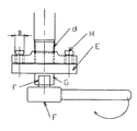
図2は、図1の示す、ねじ込み式フランジIのピッチA、穴径B、厚みCに合わせて作った治具Eを、ねじ込み式フランジに取付けた状態の図である。
治具Eには、ねじ込み式フランジIのピッチAに合わせて丸型の軸Hが二本出ている。
丸型の軸Hの軸径b1は、ねじ込み式フランジIの穴径Bに入るように合わせている。
丸型の軸Hは、段付ピンで、その頭部は、大きい径b1より少し小さい。
段付ピンの小さい径b2を有する小径部の高さはフランジの厚みCより少し高い。
段付き形状なので、治具Eに回転を加えると穴径Bに引っ掛かりとなり固定される仕組みである。
又丸型の軸Hは、小径部が丸型をしている為、引っ掛かりとなったとき、ねじ込み式フランジIに傷を付けることはない。FIG. 2 is a view showing a state in which a jig E made in accordance with the pitch A, the hole diameter B, and the thickness C of the screw-in flange I shown in FIG. 1 is attached to the screw-in flange.
Two round shafts H appear on the jig E in accordance with the pitch A of the screw-in flange I.
The shaft diameter b1 of the round shaft H is adjusted so as to enter the hole diameter B of the screw-in flange I.
The round shaft H is a stepped pin whose head is slightly smaller than the large diameter b1.
The height of the small diameter portion having the small diameter b2 of the stepped pin is slightly higher than the thickness C of the flange.
Since it has a stepped shape, when the jig E is rotated, it is caught in the hole diameter B and fixed.
In addition, since the round shaft H has a round shape at the small diameter portion, the threaded flange I will not be damaged when caught.
治具Eには、ラチェットハンドルFの差込角fが入るアダプターGがある。
又ラチェットハンドルのかわりに、六角レンチを用いてもよい。
更にスパナ、モンキーを使用する場合は、アダプターGの外形を四角や六角の多角形にする。
アダプターGは、溶接、又は鋳造時に成型される。The jig E has an adapter G into which the insertion angle f of the ratchet handle F is inserted.
A hexagon wrench may be used instead of the ratchet handle.
Furthermore, when using a wrench or monkey, the external shape of the adapter G is a square or hexagonal polygon.
The adapter G is molded at the time of welding or casting.
作業手順として図3のようにラチェットハンドルFの差込角fを、アダプターGに差し込む。
配管dのねじ部分にねじ込み式フランジIを軽く手でねじ込み、治具Eの丸型の軸Hを穴径Bに差込み引っ掛ける。
ラチェットハンドルFを回しねじ込み式フランジIを締め付け、及び緩める事が出来る。As an operation procedure, the insertion angle f of the ratchet handle F is inserted into the adapter G as shown in FIG.
The screw-in flange I is lightly screwed into the threaded portion of the pipe d by hand, and the round shaft H of the jig E is inserted into the hole diameter B and hooked.
The ratchet handle F can be turned to tighten and loosen the screwed flange I.
A ねじ込み式フランジの円周
B ねじ込み式フランジの穴径
C ねじ込み式フランジの厚み
D 雌ねじ
E 治具
F ラチェットハンドル
G アダプター
b1 丸型の軸の径
b2 段付き形状の径
b3 段付き形状の高さA Threaded flange circumference B Screwed flange hole diameter C Screwed flange thickness D Female thread E Jig F Ratchet handle G Adapter b1 Round shaft diameter b2 Stepped diameter b3 Stepped height
Claims (2)
Priority Applications (1)
| Application Number | Priority Date | Filing Date | Title |
|---|---|---|---|
| JP2013002926U JP3185919U (en) | 2013-05-08 | 2013-05-08 | Fastening jig |
Applications Claiming Priority (1)
| Application Number | Priority Date | Filing Date | Title |
|---|---|---|---|
| JP2013002926U JP3185919U (en) | 2013-05-08 | 2013-05-08 | Fastening jig |
Publications (1)
| Publication Number | Publication Date |
|---|---|
| JP3185919U true JP3185919U (en) | 2013-09-12 |
Family
ID=50429634
Family Applications (1)
| Application Number | Title | Priority Date | Filing Date |
|---|---|---|---|
| JP2013002926U Expired - Fee Related JP3185919U (en) | 2013-05-08 | 2013-05-08 | Fastening jig |
Country Status (1)
| Country | Link |
|---|---|
| JP (1) | JP3185919U (en) |
Cited By (1)
| Publication number | Priority date | Publication date | Assignee | Title |
|---|---|---|---|---|
| CN106065873A (en) * | 2016-08-09 | 2016-11-02 | 莱芜钢铁集团有限公司 | Gas-blowing engine jiggering instrument |
-
2013
- 2013-05-08 JP JP2013002926U patent/JP3185919U/en not_active Expired - Fee Related
Cited By (2)
| Publication number | Priority date | Publication date | Assignee | Title |
|---|---|---|---|---|
| CN106065873A (en) * | 2016-08-09 | 2016-11-02 | 莱芜钢铁集团有限公司 | Gas-blowing engine jiggering instrument |
| CN106065873B (en) * | 2016-08-09 | 2019-09-06 | 莱芜钢铁集团有限公司 | Gas-blowing engine jiggering tool |
Similar Documents
| Publication | Publication Date | Title |
|---|---|---|
| US9687968B2 (en) | Anti-slip wrench-type tool | |
| US11045925B2 (en) | Anti-slip fastener remover tool | |
| US10882162B2 (en) | Spherical anti-slip fastener remover | |
| US20050183548A1 (en) | Apparatus for removing damaged fasteners | |
| TWI742234B (en) | Spherical anti-slip fastener remover | |
| US20170252905A1 (en) | Anti-slip Wrench-Type Tool | |
| WO2021208830A1 (en) | Anti-disassembly joint and anti-disassembly joint assembly | |
| CN207509146U (en) | A kind of stud fastening tool | |
| EP1676675A1 (en) | Tool for tightening security nut, tool for releasing security nut, tool for both tightening and releasing security nut, and security nut for exclusive use of these tools | |
| JP2020528127A (en) | Plugs and bolts | |
| US9789592B2 (en) | Rotary tool | |
| JP3185919U (en) | Fastening jig | |
| US20100294087A1 (en) | Tool sleeve clamping structure | |
| US20170136615A1 (en) | Wrench System | |
| JP3137679U (en) | Spanner wrench | |
| WO2010091451A1 (en) | Scaffolding tool | |
| KR20090114055A (en) | A wrench for pluming | |
| TWI807482B (en) | Multi-grip socket bit | |
| CN205600575U (en) | Portable multi -functional emergent spanner | |
| JP3184507U (en) | Fastening jig | |
| US9003932B2 (en) | Locknut wrench, leveling device and screwdriver combination tool | |
| CN220279492U (en) | Spanner wrench | |
| JP3214658U (en) | Screw extractor | |
| CN203141366U (en) | Triangular combination wrench | |
| JP2011001967A (en) | Bolt tightening and loosening method and bolt |
Legal Events
| Date | Code | Title | Description |
|---|---|---|---|
| A521 | Written amendment |
Free format text: JAPANESE INTERMEDIATE CODE: A523 Effective date: 20130624 |
|
| R150 | Certificate of patent or registration of utility model |
Free format text: JAPANESE INTERMEDIATE CODE: R150 |
|
| A711 | Notification of change in applicant |
Free format text: JAPANESE INTERMEDIATE CODE: A711 Effective date: 20140123 |
|
| S111 | Request for change of ownership or part of ownership |
Free format text: JAPANESE INTERMEDIATE CODE: R323113 |
|
| R350 | Written notification of registration of transfer |
Free format text: JAPANESE INTERMEDIATE CODE: R350 |
|
| LAPS | Cancellation because of no payment of annual fees |