JP3178924U - Power strip - Google Patents
Power strip Download PDFInfo
- Publication number
- JP3178924U JP3178924U JP2012600041U JP2012600041U JP3178924U JP 3178924 U JP3178924 U JP 3178924U JP 2012600041 U JP2012600041 U JP 2012600041U JP 2012600041 U JP2012600041 U JP 2012600041U JP 3178924 U JP3178924 U JP 3178924U
- Authority
- JP
- Japan
- Prior art keywords
- socket
- exterior panel
- wall
- plug
- power strip
- Prior art date
- Legal status (The legal status is an assumption and is not a legal conclusion. Google has not performed a legal analysis and makes no representation as to the accuracy of the status listed.)
- Expired - Fee Related
Links
Images


Classifications
-
- H—ELECTRICITY
- H01—ELECTRIC ELEMENTS
- H01R—ELECTRICALLY-CONDUCTIVE CONNECTIONS; STRUCTURAL ASSOCIATIONS OF A PLURALITY OF MUTUALLY-INSULATED ELECTRICAL CONNECTING ELEMENTS; COUPLING DEVICES; CURRENT COLLECTORS
- H01R25/00—Coupling parts adapted for simultaneous co-operation with two or more identical counterparts, e.g. for distributing energy to two or more circuits
- H01R25/003—Coupling parts adapted for simultaneous co-operation with two or more identical counterparts, e.g. for distributing energy to two or more circuits the coupling part being secured only to wires or cables
-
- H—ELECTRICITY
- H01—ELECTRIC ELEMENTS
- H01R—ELECTRICALLY-CONDUCTIVE CONNECTIONS; STRUCTURAL ASSOCIATIONS OF A PLURALITY OF MUTUALLY-INSULATED ELECTRICAL CONNECTING ELEMENTS; COUPLING DEVICES; CURRENT COLLECTORS
- H01R13/00—Details of coupling devices of the kinds covered by groups H01R12/70 or H01R24/00 - H01R33/00
- H01R13/46—Bases; Cases
- H01R13/514—Bases; Cases composed as a modular blocks or assembly, i.e. composed of co-operating parts provided with contact members or holding contact members between them
Landscapes
- Details Of Connecting Devices For Male And Female Coupling (AREA)
- Connector Housings Or Holding Contact Members (AREA)
Abstract
【課題】複数の連結可能なソケットで構成される電源ストリップ(テーブルタップ)を提供する。
【解決手段】側部電気プラグは、電源コードソケット7のベースに垂直な垂直方向に側部電気受け口8に差し込まれ、これにより延長ソケットを電源コードソケット7に接続する。延長ソケットは、2つ延長ソケットを互いに接続するために、反対側に段差側壁をさらに有する。電源ストリップは、電源コードソケット7または延長ソケットの受け口8へ挿入可能なプラグを有する端部ピースを有する。突起・溝係合、および留め具・凹部係合が、ソケット7および端部ピースの係合段差側壁に形成される。
【選択図】図1A power strip (table tap) including a plurality of connectable sockets is provided.
A side electric plug is inserted into a side electric receptacle in a direction perpendicular to a base of a power cord socket, thereby connecting an extension socket to the power cord socket. The extension socket further has a stepped side wall on the opposite side for connecting the two extension sockets to each other. The power strip has an end piece with a plug that can be inserted into the power cord socket 7 or the receptacle 8 of the extension socket. Protrusion / groove engagement and fastener / recess engagement are formed on the engagement step side walls of the socket 7 and end piece.
[Selection] Figure 1
Description
関連出願の相互参照
本願は、2009年10月12日に出願した中国特許出願200920244752.7号の優先権を主張し、その内容全体をここに参照として援用する。
CROSS REFERENCE TO RELATED APPLICATION This application claims the priority of Chinese Patent Application No. 200920244752.7 filed on October 12, 2009, the entire contents of which are hereby incorporated by reference.
本願は、概して電源ストリップに関し、特に複数の連結可能なソケットで形成される電源ストリップ(テーブルタップ)に関する。 The present application relates generally to power strips, and more particularly to power strips (table taps) formed of a plurality of connectable sockets.
現在の技術において、電気器具は、屋内あるいは屋外のソケットであって、壁に固定されるまたは延長コードに接続されるソケットからの電気を得る。そのためには、ソケットに電気器具の電気プラグを挿入することにより、電源をソケットの電極に接続する。これにより、プラグ電極がソケット電極と接触し、電気器具に電気を供給できる。通常、出力コンセント数は固定である。しかしながら、実際の使用時において、必要とされる出力コンセント数は一定ではない。出力コンセント数が不十分であって、さらなる電気器具が必要な場合、出力コンセント数が足らなくなる。この問題に対する既存の解決法は、第1の電源ストリップの電気プラグを、既存の出力コンセント数リソースの残りの電気ソケットに挿入することである。出力コンセント数がさらに必要な場合、第2電源ストリップの電気プラグを第1電源ストリップの残りの電気ソケットに挿入することになる。しかしながら、この解決法の1つの欠点は、一の電気ソケットがさらなる電源ストリップの電気プラグを受けることにある。これは出力コンセント数リソースの無駄である。また、既存の出力コンセント数の上およびその周辺の空間の無駄である。他の欠点は、既存の出力コンセント数とさらなる電源ストリップとの間の接続が安定していないということにある。既存の出力コンセント数とさらなる電源ストリップとが、電源ストリップの一端の電気プラグによってのみ接続されるからである。 In current technology, the appliance is an indoor or outdoor socket that gets electricity from a socket that is fixed to the wall or connected to an extension cord. To do so, the power supply is connected to the socket electrode by inserting an electrical plug of the appliance into the socket. Thereby, a plug electrode contacts a socket electrode and can supply electricity to an electric appliance. Usually, the number of output outlets is fixed. However, in actual use, the number of output outlets required is not constant. If the number of output outlets is insufficient and additional electrical appliances are required, the number of output outlets will be insufficient. An existing solution to this problem is to insert the electrical plug of the first power strip into the remaining electrical socket of the existing output outlet number resource. If more output outlets are needed, the electrical plug of the second power strip will be inserted into the remaining electrical socket of the first power strip. However, one drawback of this solution is that one electrical socket receives an electrical plug of a further power strip. This is a waste of the number of output outlets. In addition, there is a waste of space above and around the number of existing output outlets. Another drawback is that the connection between the number of existing outlets and the further power strip is not stable. This is because the existing number of output outlets and the further power strip are connected only by an electrical plug at one end of the power strip.
上記の背景技術の説明は電源ストリップの理解する助けるためのものであって、本願において開示する電源ストリップに関係する従来技術を説明あるいは構成することを自認するものではなく、引用した引用文献は本願の実用新案請求の範囲の進歩性に対する材料と見なすことを自認するものではない。 The above background art description is intended to assist in understanding the power strip, and is not an admission that it describes or constitutes prior art related to the power strip disclosed herein. We do not admit that we consider this as a material for the inventive step of the claims of the utility model.
一の面では、複数の連結可能なソケットで構成される電源ストリップを提供する。電源ストリップは、電源コードと、第1ソケットと、第2ソケットと、を備える。 In one aspect, a power strip comprising a plurality of connectable sockets is provided. The power strip includes a power cord, a first socket, and a second socket.
第1ソケットは、外装パネルと、ベースと、第1段差側壁と、メイン電気受け口と、側部電気受け口と、を有する。第1段差側壁は、ベースに沿って延設される第1段差部が形成される。メイン電気受け口は、外装パネルに配置される。側部電気受け口は、外装パネルと概ね同じ方向に面する第1段差部の受け口配置壁に配置される。メインおよび側部電気受け口は電源コードに電気的に連結される。 The first socket includes an exterior panel, a base, a first step side wall, a main electrical receptacle, and a side electrical receptacle. The first step side wall is formed with a first step portion extending along the base. The main electrical receptacle is disposed on the exterior panel. The side electric receptacle is arranged on the receptacle arrangement wall of the first step portion facing substantially the same direction as the exterior panel. The main and side electrical receptacles are electrically connected to the power cord.
第2ソケットであって、外装パネルと、ベースと、第2段差側壁と、メイン電気受け口と、側部電気プラグと、を有する。第2段差側壁は、第2ソケットの外装パネルに沿って延設される第2段差部が形成されるとともに、第1段差側壁とは反転した形状で第2ソケットの一方の側に形成される。メイン電気受け口は、第2ソケットの外装パネルに配置される。側部電気プラグは、第2ソケットの外装パネルと反対に面する第2段差部のプラグ配置壁に配置される。側部電気プラグは第2ソケットのメイン電気受け口に電気的に連結される。 The second socket has an exterior panel, a base, a second stepped side wall, a main electrical receptacle, and a side electrical plug. The second step side wall is formed with a second step portion extending along the exterior panel of the second socket, and is formed on one side of the second socket in a shape reversed from the first step side wall. . The main electrical receptacle is disposed on the exterior panel of the second socket. The side electric plug is arranged on the plug arrangement wall of the second step portion facing away from the exterior panel of the second socket. The side electrical plug is electrically connected to the main electrical receptacle of the second socket.
第2ソケットの側部電気プラグが第1ソケットの側部電気受け口へとベースに垂直な方向に挿入可能であり、これにより、第1および第2ソケットを互いに接続できる。 A side electrical plug of the second socket can be inserted into the side electrical receptacle of the first socket in a direction perpendicular to the base, so that the first and second sockets can be connected to each other.
一の態様では、第2ソケットは、さらに、第3段差側壁と、側部電気受け口と、を有する。第3段差側壁は、第2ソケットのベースに沿って延設される第3段差部が形成されるとともに、第2ソケットの他方の側に形成される。側部電気受け口は、第2ソケットの外装パネルと概ね同じ方向に面する第3段差部の受け口配置壁に配置される。第2ソケットの側部電気受け口は、第2ソケットのメイン電気受け口に電気的に連結されるとともに、他の第2ソケットの側部電気プラグを受けるよう構成されている。 In one mode, the 2nd socket further has the 3rd level difference side wall and the side part electric receptacle. The third step side wall is formed on the other side of the second socket while a third step portion extending along the base of the second socket is formed. The side electric receptacle is arranged on the receptacle arrangement wall of the third step portion facing substantially the same direction as the exterior panel of the second socket. The side socket of the second socket is electrically connected to the main socket of the second socket and is configured to receive the side plug of the other second socket.
一の態様では、電源ストリップは、保護端部ピースをさらに有する。保護端部ピースは、外装パネルと、ベースと、保護端部ピースの外装パネルに沿って延設される第4段差部が形成されるとともに、第1または第3段差側壁とは反転した形状で形成される第4段差側壁と、保護端部ピースの外装パネルと概ね反対に面する第4段差部のプラグ配置壁に配置される側部プラグであって、保護端部ピースの側部プラグは、第1または第2ソケットの側部電気受け口へ挿入可能である側部プラグと、を有する。 In one aspect, the power strip further comprises a protective end piece. The protective end piece is formed with an exterior panel, a base, and a fourth step portion that extends along the exterior panel of the protective end piece, and is inverted from the first or third step side wall. A side plug that is disposed on a plug-positioning wall of a fourth stepped side wall and a fourth stepped portion that faces the outer panel of the protective end piece substantially oppositely, the side plug of the protective end piece being A side plug that can be inserted into the side electrical receptacle of the first or second socket.
一の態様では、第1および第3段差側壁のそれぞれは、接続されているベースに垂直な第1壁を有する。逆向きの第2および第4段差側壁のそれぞれは、接続されているベースに垂直な係合第2壁を有する。第1および第3段差側壁のそれぞれは、接続されている外装パネルに垂直な第3壁を有する。逆向きの第2および第4段差側壁のそれぞれは、接続されている外装パネルに垂直な係合第4壁を有する。第1、第2、第3および第4壁は互いに平行である。 In one aspect, each of the first and third stepped sidewalls has a first wall perpendicular to the connected base. Each of the opposite second and fourth step side walls has an engaging second wall perpendicular to the connected base. Each of the first and third stepped side walls has a third wall perpendicular to the connected exterior panel. Each of the opposite second and fourth stepped side walls has an engaging fourth wall perpendicular to the connected exterior panel. The first, second, third and fourth walls are parallel to each other.
一の態様では、第1および第2壁の一方には、接続されているベースに垂直な細長い突起が配置されており、また、第1および第2壁の他方には、接続されているベースに垂直な、細長い突起と摺動可能に係合する細長い溝が配置されている。 In one aspect, one of the first and second walls is provided with an elongated protrusion perpendicular to the connected base, and the other of the first and second walls is connected to the base. An elongate groove slidably engaged with the elongate protrusion is disposed perpendicular to.
一の態様では、第1および第2壁の一方には凹部が配置されており、第1および第2壁の他方には凹部に挿入されるとともに、係合する突出留め具が配置されている。 In one aspect, a recess is disposed on one of the first and second walls, and a projecting fastener is disposed on the other of the first and second walls and inserted into the recess. .
一の態様では、第3および第4壁の一方には、接続されている外装パネルに垂直な細長い突起が配置されており、また、第3および第4壁の他方には、接続されている外装パネルに垂直な、細長い突起と摺動可能に係合する細長い溝が配置されている。 In one aspect, one of the third and fourth walls is provided with an elongated protrusion perpendicular to the connected exterior panel, and is connected to the other of the third and fourth walls. An elongated groove is slidably engaged with the elongated protrusion perpendicular to the exterior panel.
一の態様では、細長い突起および溝は、概ね長方形状の断面を有する。 In one aspect, the elongated protrusions and grooves have a generally rectangular cross section.
一の態様では、細長い突起および溝は、概ねありつぎ状の断面を有する。 In one aspect, the elongated protrusions and grooves have a generally dovetail cross section.
一の態様では、側部電気プラグは第2ソケットのプラグ配置壁に垂直である。 In one aspect, the side electrical plug is perpendicular to the plug placement wall of the second socket.
一の態様では、第2ソケットの側部電気プラグは2ピンの電気プラグであり、第1ソケットの側部電気受け口は2ピンの電気受け口である。 In one aspect, the side electrical plug of the second socket is a 2-pin electrical plug and the side electrical receptacle of the first socket is a 2-pin electrical receptacle.
一の態様では、第2ソケットの側部電気プラグは3ピンの電気プラグであり、第1ソケットの側部電気受け口は3ピンの電気受け口である。 In one aspect, the side electrical plug of the second socket is a 3-pin electrical plug and the side electrical receptacle of the first socket is a 3-pin electrical receptacle.
一の態様では、第2ソケットの側部電気プラグのピンが、プラグ配置壁に沿って一列に配置されており、また、第1ソケットの側部電気受け口の対応する開口部が、受け口配置壁に沿って一列に配置されている。 In one aspect, the pins of the side electrical plug of the second socket are arranged in a line along the plug placement wall, and the corresponding opening of the side electrical receptacle of the first socket is a receptacle placement wall. Are arranged in a line along.
一の態様では、第1ソケットの外装パネルと第1ソケットの受け口配置壁との間の距離は、第2ソケットの外装パネルと第2ソケットのプラグ配置壁との間の距離と実質的に同じであり、また、第1ソケットの受け口配置壁と第1ソケットのベースとの間の距離は、第2ソケットのプラグ配置壁と第2ソケットのベースとの間の距離と実質的に同じである。 In one aspect, the distance between the exterior panel of the first socket and the receptacle arrangement wall of the first socket is substantially the same as the distance between the exterior panel of the second socket and the plug arrangement wall of the second socket. And the distance between the receptacle arrangement wall of the first socket and the base of the first socket is substantially the same as the distance between the plug arrangement wall of the second socket and the base of the second socket. .
一の態様では、第1および第2ソケットが互いに接続されると、第1および第2ソケットの外装パネルが同じ面上に配置される。 In one aspect, when the first and second sockets are connected to each other, the exterior panels of the first and second sockets are arranged on the same surface.
一の態様では、第1および第2ソケットのそれぞれは電源スイッチを有する。 In one aspect, each of the first and second sockets has a power switch.
一の態様では、第1および第2ソケットのそれぞれはネオン管パワーインジケータを有する。 In one aspect, each of the first and second sockets has a neon tube power indicator.
他の面では、電源ストリップであって、第1ソケットと、第2ソケットと、を備える電源ストリップを提供する。 In another aspect, a power strip is provided that includes a first socket and a second socket.
第1ソケットであって、外装パネルと、ベースと、第1段差側壁と、メイン電気受け口と、第1電気コネクタと、を有する。第1段差側壁は、ベースに沿って延設される第1段差部が形成される。メイン電気受け口は、外装パネルに配置される。第1電気コネクタは、第1段差側壁に配置される。メイン電気受け口および第1電気コネクタが電源コードに電気的に連結される。 The first socket includes an exterior panel, a base, a first step side wall, a main electrical receptacle, and a first electrical connector. The first step side wall is formed with a first step portion extending along the base. The main electrical receptacle is disposed on the exterior panel. The first electrical connector is disposed on the first step side wall. The main electrical receptacle and the first electrical connector are electrically connected to the power cord.
第2ソケットは、外装パネルと、ベースと、第2段差側壁と、メイン電気受け口と、第2電気コネクタと、を有する。第2段差側壁は、第2ソケットの外装パネルに沿って延設される第2段差部が形成されるとともに、第1段差側壁とは反転した形状で第2ソケットの一方の側に形成される。メイン電気受け口は、第2ソケットの外装パネルに配置される。第2電気コネクタは、第2段差側壁に配置されるとともに、第2ソケットのメイン電気受け口に電気的に連結されており第1ソケットの第1電気コネクタに連結可能である。 The second socket includes an exterior panel, a base, a second step side wall, a main electrical receptacle, and a second electrical connector. The second step side wall is formed with a second step portion extending along the exterior panel of the second socket, and is formed on one side of the second socket in a shape reversed from the first step side wall. . The main electrical receptacle is disposed on the exterior panel of the second socket. The second electrical connector is disposed on the second step side wall, and is electrically connected to the main electrical receptacle of the second socket, and can be connected to the first electrical connector of the first socket.
一の態様では、第2ソケットが、第3段差側壁と、第3電気コネクタと、をさらに有する。第3段差側壁は、第2ソケットのベースに沿って延設される第3段差部が形成されるとともに、第2ソケットの他方の側に形成される。第3電気コネクタは、第3段差側壁に配置されるとともに、第2ソケットのメイン電気受け口に電気的に連結されており他の第2ソケットの第2電気コネクタに連結可能である。 In one mode, the 2nd socket further has the 3rd level difference side wall and the 3rd electric connector. The third step side wall is formed on the other side of the second socket while a third step portion extending along the base of the second socket is formed. The third electrical connector is disposed on the third stepped side wall, and is electrically connected to the main electrical receptacle of the second socket, and can be connected to the second electrical connector of the other second socket.
一の態様では、電源ストリップは、保護端部ピースをさらに備える。保護端部ピースは、外装パネルと、ベースと、第4段差側壁と、第4電気コネクタと、を有する。第4段差側壁は、保護端部ピースの外装パネルに沿って延設される第4段差部が形成されるとともに、第1または第3段差側壁とは反転した形状で形成される。第4電気コネクタは、第4段差側壁に配置されるとともに、第1ソケットの第1電気コネクタまたは第2ソケットの第3電気コネクタに連結可能である。 In one aspect, the power strip further comprises a protective end piece. The protective end piece includes an exterior panel, a base, a fourth step side wall, and a fourth electrical connector. The fourth step side wall is formed with a fourth step portion that extends along the outer panel of the protective end piece, and has a shape reversed from the first or third step side wall. The fourth electrical connector is disposed on the fourth step side wall and is connectable to the first electrical connector of the first socket or the third electrical connector of the second socket.
一の態様では、第1電気コネクタは、第1ソケットの外装パネルと概ね同じ方向に面する第1段差部の受け口配置壁に配置される電気受け口である。第2電気コネクタは、第2ソケットの外装パネルと概ね反対に面する第2段差部のプラグ配置壁に配置される電気プラグである。第3電気コネクタは、第2ソケットの外装パネルと概ね同じ方向に面する第3段差部の受け口配置壁に配置される電気受け口である。第4電気コネクタは、保護端部ピースの外装パネルと概ね反対に面する第4段差部のプラグ配置壁に配置されるプラグである。第2ソケットの電気プラグおよび保護端部ピースのプラグは、第1または第2ソケットの電気受け口へとそのベースに垂直な方向に挿入可能である。 In one aspect, the first electrical connector is an electrical receptacle that is disposed on the receptacle arrangement wall of the first step portion that faces substantially the same direction as the exterior panel of the first socket. The second electrical connector is an electrical plug disposed on the plug placement wall of the second stepped portion facing substantially opposite to the exterior panel of the second socket. A 3rd electrical connector is an electrical receptacle arrange | positioned at the receptacle arrangement | positioning wall of the 3rd level | step-difference part facing the substantially same direction as the exterior panel of a 2nd socket. A 4th electrical connector is a plug arrange | positioned at the plug arrangement | positioning wall of the 4th level | step-difference part facing substantially opposite to the exterior panel of a protection edge part piece. The electrical plug of the second socket and the plug of the protective end piece can be inserted into the electrical receptacle of the first or second socket in a direction perpendicular to its base.
一の態様では、第1および第3段差側壁のそれぞれは、接続されているベースに垂直な第1壁を有する。逆向きの第2および第4段差側壁のそれぞれは、接続されているベースに垂直な係合第2壁を有する。第1および第3段差側壁のそれぞれは、接続されている外装パネルに垂直な第3壁を有する。逆向きの第2および第4段差側壁のそれぞれは、接続されている外装パネルに垂直な係合第4壁を有する。第1、第2、第3および第4壁は互いに平行である。 In one aspect, each of the first and third stepped sidewalls has a first wall perpendicular to the connected base. Each of the opposite second and fourth step side walls has an engaging second wall perpendicular to the connected base. Each of the first and third stepped side walls has a third wall perpendicular to the connected exterior panel. Each of the opposite second and fourth stepped side walls has an engaging fourth wall perpendicular to the connected exterior panel. The first, second, third and fourth walls are parallel to each other.
一の態様では、第1および第2壁の一方には、接続されているベースに垂直な細長い突起が配置されており、また、第1および第2壁の他方には、接続されているベースに垂直な、細長い突起と摺動可能に係合する細長い溝が配置されている。 In one aspect, one of the first and second walls is provided with an elongated protrusion perpendicular to the connected base, and the other of the first and second walls is connected to the base. An elongate groove slidably engaged with the elongate protrusion is disposed perpendicular to.
一の態様では、第1および第2壁の一方には凹部が配置されており、第1および第2壁の他方には凹部に挿入されるとともに、係合する突出留め具が配置されている。 In one aspect, a recess is disposed on one of the first and second walls, and a projecting fastener is disposed on the other of the first and second walls and inserted into the recess. .
一の態様では、第3および第4壁の一方には、接続されている外装パネルに垂直な細長い突起が配置されており、また、第3および第4壁の他方には、接続されている外装パネルに垂直な、細長い突起と摺動可能に係合する細長い溝が配置されている。 In one aspect, one of the third and fourth walls is provided with an elongated protrusion perpendicular to the connected exterior panel, and is connected to the other of the third and fourth walls. An elongated groove is slidably engaged with the elongated protrusion perpendicular to the exterior panel.
一の態様では、細長い突起および溝は、概ね長方形状の断面を有する。 In one aspect, the elongated protrusions and grooves have a generally rectangular cross section.
一の態様では、細長い突起および溝は、概ねありつぎ状の断面を有する
一の態様では、側部電気プラグは第2ソケットのプラグ配置壁に垂直である。
In one aspect, the elongated protrusions and grooves have a generally dovetail cross section. In one aspect, the side electrical plug is perpendicular to the plug placement wall of the second socket.
一の態様では、第2ソケットの側部電気プラグは2ピンの電気プラグであり、第1ソケットの側部電気受け口は2ピンの電気受け口である。 In one aspect, the side electrical plug of the second socket is a 2-pin electrical plug and the side electrical receptacle of the first socket is a 2-pin electrical receptacle.
一の態様では、第2ソケットの側部電気プラグは3ピンの電気プラグであり、第1ソケットの側部電気受け口は3ピンの電気受け口である。 In one aspect, the side electrical plug of the second socket is a 3-pin electrical plug and the side electrical receptacle of the first socket is a 3-pin electrical receptacle.
一の態様では、第2ソケットの側部電気プラグのピンが、プラグ配置壁に沿って一列に配置されており、また、第1ソケットの側部電気受け口の対応する開口部が、受け口配置壁に沿って一列に配置されている。 In one aspect, the pins of the side electrical plug of the second socket are arranged in a line along the plug placement wall, and the corresponding opening of the side electrical receptacle of the first socket is a receptacle placement wall. Are arranged in a line along.
一の態様では、第1ソケットの外装パネルと第1ソケットの受け口配置壁との間の距離は、第2ソケットの外装パネルと第2ソケットのプラグ配置壁との間の距離と実質的に同じであり、また、第1ソケットの受け口配置壁と第1ソケットのベースとの間の距離は、第2ソケットのプラグ配置壁と第2ソケットのベースとの間の距離と実質的に同じである。 In one aspect, the distance between the exterior panel of the first socket and the receptacle arrangement wall of the first socket is substantially the same as the distance between the exterior panel of the second socket and the plug arrangement wall of the second socket. And the distance between the receptacle arrangement wall of the first socket and the base of the first socket is substantially the same as the distance between the plug arrangement wall of the second socket and the base of the second socket. .
一の態様では、第1および第2ソケットが互いに接続されると、第1および第2ソケットの外装パネルが同じ面上に配置される。 In one aspect, when the first and second sockets are connected to each other, the exterior panels of the first and second sockets are arranged on the same surface.
一の態様では、第1および第2ソケットのそれぞれは電源スイッチを有する。 In one aspect, each of the first and second sockets has a power switch.
一の態様では、第1および第2ソケットのそれぞれはネオン管パワーインジケータを有する。 In one aspect, each of the first and second sockets has a neon tube power indicator.
さらに他の面では、電源ストリップを構成するソケットキットを提供する。ソケットキットは、電源ソケットと、延長ソケットと、を備える。 In yet another aspect, a socket kit for forming a power strip is provided. The socket kit includes a power socket and an extension socket.
電源ソケットは、外装パネルと、ベースと、第1段差側壁と、第1電気コネクタと、を有する。第1段差側壁は、ベースに沿って延設される第1段差部が形成される。第1電気コネクタは、外装パネルに配置されるメイン電気受け口と、第1段差側壁に配置される。メイン電気受け口および第1電気コネクタが電源コードに電気的に連結される。 The power socket includes an exterior panel, a base, a first step side wall, and a first electrical connector. The first step side wall is formed with a first step portion extending along the base. The first electrical connector is disposed on the main electrical receiving port disposed on the exterior panel and the first step side wall. The main electrical receptacle and the first electrical connector are electrically connected to the power cord.
延長ソケットであって、外装パネルと、ベースと、第2段差側壁と、第2電気コネクタと、を有する。第2段差側壁は、延長ソケットの外装パネルに沿って延設される第2段差部が形成されるとともに、第1段差側壁とは反転した形状で延長ソケットの一方の側に形成される。メイン電気受け口は、延長ソケットの外装パネルに配置される。第2電気コネクタは、第2段差側壁に配置されるとともに、延長ソケットのメイン電気受け口に電気的に連結されており電源コードソケットの第1電気コネクタに連結可能である。 An extension socket having an exterior panel, a base, a second step side wall, and a second electrical connector. The second step side wall is formed with a second step portion extending along the exterior panel of the extension socket, and is formed on one side of the extension socket in a shape reversed with respect to the first step side wall. The main electrical receptacle is disposed on the exterior panel of the extension socket. The second electrical connector is disposed on the second stepped side wall and is electrically connected to the main electrical receptacle of the extension socket and can be connected to the first electrical connector of the power cord socket.
一の態様では、延長ソケットが、第3段差側壁と、第3電気コネクタと、をさらに有する。第3段差側壁は、延長ソケットのベースに沿って延設される第3段差部が形成されるとともに、延長ソケットの他方の側に形成される。第3電気コネクタは、第3段差側壁に配置されるとともに、延長ソケットのメイン電気受け口に電気的に連結されており他の延長ソケットの第2電気コネクタに連結可能である。 In one aspect, the extension socket further includes a third step side wall and a third electrical connector. The third step side wall is formed on the other side of the extension socket while a third step portion extending along the base of the extension socket is formed. The third electrical connector is disposed on the third stepped side wall, and is electrically connected to the main electrical receptacle of the extension socket, and can be connected to the second electrical connector of another extension socket.
一の態様では、ソケットキットは、さらに、保護端部ピースを備える。保護端部ピースが、外装パネルと、ベースと、第4段差側壁と、第4電気コネクタと、を有する。第4段差側壁は、保護端部ピースの外装パネルに沿って延設される第4段差部が形成されるとともに、第1または第3段差側壁とは反転した形状で形成される。第4電気コネクタは、第4段差側壁に配置されるとともに、電源コードソケットの第1電気コネクタまたは延長ソケットの第3電気コネクタに連結可能である。 In one aspect, the socket kit further comprises a protective end piece. The protective end piece includes an exterior panel, a base, a fourth step side wall, and a fourth electrical connector. The fourth step side wall is formed with a fourth step portion that extends along the outer panel of the protective end piece, and has a shape reversed from the first or third step side wall. The fourth electrical connector is disposed on the fourth step side wall and can be connected to the first electrical connector of the power cord socket or the third electrical connector of the extension socket.
一の態様では、第1電気コネクタは、電源コードソケットの外装パネルと概ね同じ方向に面する第1段差部の受け口配置壁に配置される電気受け口である。第2電気コネクタは、延長ソケットの外装パネルと概ね反対に面する第2段差部のプラグ配置壁に配置される電気プラグである。第3電気コネクタは、延長ソケットの外装パネルと概ね同じ方向に面する第3段差部の受け口配置壁に配置される電気受け口である。第4電気コネクタは、保護端部ピースの外装パネルと概ね反対に面する第4段差部のプラグ配置壁に配置されるプラグである。延長ソケットの電気プラグおよび保護端部ピースのプラグは、電源コードソケットまたは延長ソケットの電気受け口へとそのベースに垂直な方向に挿入可能である。 In one aspect, the first electrical connector is an electrical receptacle disposed on the receptacle arrangement wall of the first step portion facing substantially the same direction as the exterior panel of the power cord socket. The second electric connector is an electric plug disposed on the plug arrangement wall of the second step portion facing substantially opposite to the exterior panel of the extension socket. A 3rd electrical connector is an electrical receptacle arrange | positioned at the receptacle arrangement | positioning wall of the 3rd level | step-difference part facing the substantially same direction as the exterior panel of an extension socket. A 4th electrical connector is a plug arrange | positioned at the plug arrangement | positioning wall of the 4th level | step-difference part facing substantially opposite to the exterior panel of a protection edge part piece. The electrical plug of the extension socket and the plug of the protective end piece can be inserted into the power cord socket or the electrical receptacle of the extension socket in a direction perpendicular to its base.
一の態様では、第1および第3段差側壁のそれぞれは、接続されているベースに垂直な第1壁を有する。逆向きの第2および第4段差側壁のそれぞれは、接続されているベースに垂直な係合第2壁を有する。第1および第3段差側壁のそれぞれは、接続されている外装パネルに垂直な第3壁を有する。逆向きの第2および第4段差側壁のそれぞれは、接続されている外装パネルに垂直な係合第4壁を有する。第1、第2、第3および第4壁は互いに平行である。 In one aspect, each of the first and third stepped sidewalls has a first wall perpendicular to the connected base. Each of the opposite second and fourth step side walls has an engaging second wall perpendicular to the connected base. Each of the first and third stepped side walls has a third wall perpendicular to the connected exterior panel. Each of the opposite second and fourth stepped side walls has an engaging fourth wall perpendicular to the connected exterior panel. The first, second, third and fourth walls are parallel to each other.
一の態様では、第1および第2壁の一方には、接続されているベースに垂直な細長い突起が配置されており、また、第1および第2壁の他方には、接続されているベースに垂直な、細長い突起と摺動可能に係合する細長い溝が配置されている。 In one aspect, one of the first and second walls is provided with an elongated protrusion perpendicular to the connected base, and the other of the first and second walls is connected to the base. An elongate groove slidably engaged with the elongate protrusion is disposed perpendicular to.
一の態様では、第1および第2壁の一方には凹部が配置されており、第1および第2壁の他方には凹部に挿入されるとともに、係合する突出留め具が配置されている。 In one aspect, a recess is disposed on one of the first and second walls, and a projecting fastener is disposed on the other of the first and second walls and inserted into the recess. .
一の態様では、第3および第4壁の一方には、接続されている外装パネルに垂直な細長い突起が配置されており、また、第3および第4壁の他方には、接続されている外装パネルに垂直な、細長い突起と摺動可能に係合する細長い溝が配置されている。 In one aspect, one of the third and fourth walls is provided with an elongated protrusion perpendicular to the connected exterior panel, and is connected to the other of the third and fourth walls. An elongated groove is slidably engaged with the elongated protrusion perpendicular to the exterior panel.
一の態様では、電源コードソケットおよび延長ソケットのそれぞれは電源スイッチを有する。 In one aspect, each of the power cord socket and the extension socket has a power switch.
一の態様では、電源コードソケットおよび延長ソケットのそれぞれはネオン管パワーインジケータを有する。 In one aspect, each of the power cord socket and the extension socket has a neon tube power indicator.
いくつかの実施形態を参照して本願において開示する電源ソケットを示し説明するが、当業者は本明細書を読んで理解することによって均等物および変形物を当然思いつくであろう。本願は、そのような均等物や変形物をすべて含むものであって、実用新案請求の範囲によってのみ規定される。 While the power socket disclosed herein is shown and described with reference to some embodiments, those skilled in the art will naturally recognize equivalents and variations upon reading and understanding this specification. The present application includes all such equivalents and modifications, and is defined only by the claims of the utility model.
本願に開示する電源コードソケットの具体的な実施形態を添付の図面を参照して例示的に説明する。 A specific embodiment of a power cord socket disclosed in the present application will be exemplarily described with reference to the accompanying drawings.
次に、本願において開示する電源ストリップの好ましい実施形態を詳細に説明する。また、以下の説明に、その実施例を示す。本願において開示する電源ストリップの例示的な実施形態を詳細に説明するが、電源ストリップの理解に特に重要でないいくつかの特徴は簡略化のために示していないことは当業者には明らかであろう。 Next, a preferred embodiment of the power strip disclosed in the present application will be described in detail. In addition, examples thereof will be shown in the following description. Although exemplary embodiments of the power strip disclosed in this application will be described in detail, it will be apparent to those skilled in the art that some features not particularly important for understanding the power strip are not shown for the sake of brevity. .
また、本願において開示する電源ストリップは、後述する詳細な実施形態に限定されず、添付の実用新案の範囲の精神あるいは範囲を逸脱することなく種々の変形および変更を当業者によってなしうることは、理解されよう。例えば、種々の例示的な実施形態のエレメントおよび/または特徴を、本開示および添付の実用新案請求の範囲内で、互いに組み合わせること、および/または互いと置き換えることもできる。 Further, the power strip disclosed in the present application is not limited to the detailed embodiments described below, and various modifications and changes can be made by those skilled in the art without departing from the spirit or scope of the attached utility model. It will be understood. For example, the elements and / or features of the various exemplary embodiments may be combined and / or replaced with each other within the scope of this disclosure and the appended utility model claims.
本開示、図面および添付の実用新案登録請求の範囲から当業者にとって明らかとなる改良や変形は、添付の実用新案登録請求の精神および範囲内である。 Improvements and modifications apparent to those skilled in the art from this disclosure, the drawings, and the appended utility model registration claims are within the spirit and scope of the appended utility model registration claims.
なお、明細書および実用新案の範囲を通じて、1つのエレメントが他のエレメントに「連結される」あるいは「接続される」場合、エレメントは他のエレメントに必ずしも固定し、留める、あるいは取り付けることを意味しない。それよりむしろ、用語「連結される」あるいは「接続される」は、あるエレメントが他のエレメントに直接的あるいは間接的に接続される、または他のエレメントとの機械的あるいは電気的な連絡状態にあること、を意味する。 Throughout the specification and utility model, when one element is “coupled” or “connected” to another element, the element does not necessarily mean fixed, fastened, or attached to the other element. . Rather, the term “coupled” or “connected” means that one element is directly or indirectly connected to another element or in mechanical or electrical communication with another element. It means that there is.
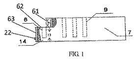
図1乃至図7は、本願において開示する第1実施形態にかかる電源ストリップを示す。電源ストリップは、電源コードおよび延長ソケット11に接続される電源コードソケット7を有することができる。図1乃至図3に示すように、電源コードソケット7は、電源コードソケット7の外装パネルに配置されるメイン電気受け口9(電極を有する)を有することができる。メイン電気受け口9は、英国規格、米国規格、中国規格または他の国の規格に応じて形成される規格電気プラグを受けるあらゆる規格の電気受け口とできる。
1 to 7 show a power strip according to a first embodiment disclosed in the present application. The power strip can have a
電源コードソケット7は、そのベースに沿って電源コードソケット7の一方の側から延設される第1段差部14が形成される第1段差側壁を有することができる。第1段差部14は、電源コードソケット7と一体的に形成することができる。側部電気受け口8は、外装パネルと概ね同じ方向に面する受け口配置壁62に配置することができる。メイン電気受け口9および側部電気受け口8は、電源コードに電気的に連結でき、したがって電源に接続できる。絶縁スリーブ(図示せず)を、側部電気受け口8内に一体的に形成することができる。図示の実施形態では、側部電気受け口8は3ピンの電気受け口である。3ピンの電気受け口8の3つの開口部は、電源コードソケット7の受け口配置壁62に沿って一列に配置することができる。
The
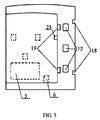
図4、図5および図6に示すように、延長ソケット11にはメイン電気受け口13が配置される。延長ソケット11は、その外装パネルに沿って延長ソケット11の一方の側から延設される第2段差部15が形成される第2段差側壁を有することができる。第2段差側壁は、第1段差側壁とは反転した形状で配置される。第2段差部15は、延長ソケット11と一体的に形成することができる。側部電気プラグ12は、延長ソケット11の外装パネルと反対に面するプラグ配置壁65に配置することができる。延長ソケット11の側部電気プラグ12は、延長ソケット11のメイン電気受け口13に電気的に連結することができる。図示の実施形態では、側部電気プラグ12は3ピンの電気プラグである。3つのピンは、延長ソケット11のプラグ配置壁65に沿って一列に配置することができる。これにより、側部電気プラグ12は、3つのピンが三角形状に配置される規格の3ピンの電気プラグと比較して、比較的横幅のない(フラットな)構成配置となる。これにより、電源コードソケット7および延長ソケット11によってこのように形成される電源ストリップの長さを低減でき、また電源ストリップによって占有される空間を低減できる。
As shown in FIGS. 4, 5 and 6, the
電源コードソケット7および延長ソケット11のそれぞれに、1つの規格の電気プラグを受けるための1つの規格の電気受け口のみが配置される例を示して説明したが、電源コードソケット7および延長ソケット11のそれぞれに、2つ以上の電気受け口を配置することも考えられる。
Although the
さらに、側部電気受け口8が電源コードソケット7に配置され、そして、側部電気プラグ12が延長ソケット11に配置される例を示して説明したが、代わりに、側部電気プラグ12は電源コードソケット7に配置することもでき、そして、側部電気受け口8は、延長ソケット11に提供することができることは理解されよう。
Further, although the example in which the side electrical receptacle 8 is disposed in the
図7は、電源コードソケット7と延長ソケット11との接続を示す。接続するために、延長ソケット11の側部電気プラグ12は、電源コードソケット7のベースに垂直な垂直方向に電源コードソケット7の側部電気受け口8に差し込まれる。延長ソケット11の側部電気プラグ12が電源コードソケット7の側部電気受け口8に差し込まれると、延長ソケット11の逆向きの第2段差側壁が電源コードソケット7の第1段差側壁と係合する。電源コードソケット7と延長ソケット11とは容易には分離できない。これにより、電源コードソケット7と延長ソケット11との接続の安定性が向上し、電源ストリップの安全性を確保できる。
FIG. 7 shows the connection between the
電源コードソケット7の高さと延長ソケット11の高さとを同じにできる。図1および図4に示すように、電源コードソケット7の垂直側壁61の高さL1(つまり電源コードソケット7の外装パネルと受け口配置壁62との間の距離)は、延長ソケット11の第2段差部15の高さL2(つまり延長ソケット11の外装パネルとプラグ配置壁65との間の距離)と実質的に同じである。さらに、電源コードソケット7の第1段差部14の高さL3(つまり電源コードソケット7の受け口配置壁62とベースとの間の距離)は、延長ソケット11の側壁66の高さL4(つまり延長ソケット11のプラグ配置壁65とベースとの間の距離)と実質的に同じである。したがって、電源コードソケット7と延長ソケット11とが互いに連結されると、電源コードソケット7および延長ソケット11の外装パネルを同じ面すなわち同じ高さに配置することができる。これにより、電源ストリップを一体的で整った外観とできる。
The height of the
電源コードソケット7の外装パネルと延長ソケット11の外装パネルとを同じ面すなわち同じ高さに配置される例を示し説明したが、電源コードソケット7の外装パネルを延長ソケット11の外装パネルより高くまたは低くできることは理解されよう。
Although the example in which the exterior panel of the
さらに、電源コードソケット7および延長ソケット11の第1側壁および第2側壁には、電源コードソケット7および延長ソケット11を互いに保持するための係合要素を形成することができる。
Furthermore, an engagement element for holding the
図1乃至図6に示すように、凸部すなわち留め具22を、電源コードソケット7のベースに垂直な第1段差側壁の垂直壁63に形成することができる。また、対応する凹部すなわち凹部23を、延長ソケット11のベースに垂直な第2段差側壁の係合垂直壁66に形成することができる。留め具22は、外側に延設される位置に留め具22を付勢するための内部バネを有するバネ付勢留め具の態様とできる。電源コードソケット7および延長ソケット11の他の適当な係合面に留め具22および凹部23を配置することができることは当業者には理解されよう。
As shown in FIGS. 1 to 6, the convex portion or the
さらに、電源コードソケット7と延長ソケット11とは、摺動可能な係合によって互いに接続することができる。図示の実施形態では、2つの垂直の細長い溝16を、電源コードソケット7の第1段差側壁の垂直壁63に形成することができ、そして、2つの対応する垂直の細長い突起19を、延長ソケット11の第2段差側壁の垂直壁66に形成することができる。延長ソケット11の側部電気プラグ12を、電源コードソケット7のベースに垂直な垂直方向に電源コードソケット7の側部電気受け口8へ挿入するとき、延長ソケット11の2つの垂直の突起19が、電源コードソケット7の2つの対応する垂直溝16内へ摺動し、これにより、電源コードソケット7と延長ソケット11とを互いに所定位置に保持できる。
Furthermore, the
溝16および突起19によって、電源コードソケット7と延長ソケット11とを接続するとき、延長ソケット11を電源コードソケット7上に正しい姿勢で位置決めすることができる。電源コードソケット7と延長ソケット11とが接続されると、係合した溝16および突起19により、電源コードソケット7と延長ソケット11との分離を防止できる。細長い溝16および細長い突起19は概ね長方形状の断面または概ねありつぎ状の断面を有することができる。
When the
2つの垂直溝16を電源コードソケット7に形成し、そして2つ垂直突起19を延長ソケット11に形成する例を示し説明したが、溝16と突起19との係合により電源コードソケット7および延長ソケット11を所望位置に保持するのに十分である限り、溝16および突起19の数、位置、ならびに形状を変更できることは、当業者には理解されよう。
Although the example in which the two
さらに、2つの垂直の細長い突起17を、電源コードソケット7の外装パネルに垂直な第1段差側壁の垂直壁61に形成することができ、そして、2つの対応する垂直の細長い溝18を、延長ソケット11の外装パネルに垂直な第2段差側壁の垂直壁64に形成することができる。延長ソケット11の側部電気プラグ12を、電源コードソケット7のベースに垂直な垂直方向に電源コードソケット7の側部電気受け口8へ挿入するとき、電源コードソケット7の2つの対応する垂直の突起17が延長ソケット11の2つの垂直溝18内へ摺動し、これにより、電源コードソケット7と延長ソケット11とをさらに一体に保持できる。
Further, two vertical elongate protrusions 17 can be formed in the
溝18および突起17は、電源コードソケット7と延長ソケット11とをよりしっかりと接続することができる。電源コードソケット7と延長ソケット11とが接続されると、係合した溝18および突起17により、電源コードソケット7と延長ソケット11との分離をよりいっそう防止できる。細長い溝18および細長い突起17は概ね長方形状の断面または概ねありつぎ状の断面を有することができる。
The
2つの垂直突起17を電源コードソケット7に形成し、そして2つ対応する垂直溝18を延長ソケット11に形成する例を示し説明したが、溝18と突起17との係合により電源コードソケット7および延長ソケット11を所望位置に保持するのに十分である限り、溝18および突起17の数、位置、ならびに形状を変更できることは、当業者には理解されよう。
Although two vertical protrusions 17 are formed on the
図2、図3、図5および図6に示すように、電源スイッチ5を、電源コードソケット7および延長ソケット11のそれぞれに配置することができる。電力スイッチ5は、電源コードソケット7および延長ソケット11のメイン電気受け口9および13の電極への電力を制御するために使用される。ネオン管パワーインジケータ6を、電源コードソケット7のメイン電気受け口9の電力状態を示すために電源コードソケット7に配置することができる。同様に、他のネオン管パワーインジケータ6を、延長ソケット11のメイン電気受け口13の電力状態を示すために延長ソケット11に配置することができる。パワーインジケータとして発光ダイオードのような他の従来の点灯デバイスを用いることができることは理解されよう。
As shown in FIGS. 2, 3, 5, and 6, the
図7に示すように、電源ストリップにおけるメイン電気受け口の数を増加するために、電源コードソケット7のベースに垂直な垂直方向(矢印で示す)に延長ソケット11の側部電気プラグ12を電源コードソケット7の側部電気受け口8に差し込むことができ、これにより、電源コードソケット7と延長ソケット11とを機械的かつ電気的に互いに接続できる。こうして、延長ソケット11が電源コードソケット7のメイン電気受け口9を覆わないようにできる。これにより、電源ストリップのコンセント(差し込み口)リソースを無駄にすることなく、メイン電気受け口の数を増加させることができる。延長ソケット11の側部電気プラグ12は、垂直方向に電源コードソケット7の側部電気受け口8に差し込まれるので、電源コードソケット7と延長ソケット11とは容易には分離することができない。これにより、接続しているソケットの機械的構造の安定性を向上できる。留め具22および凹部23を用いることにより、接続しているソケットの機械的構造の安定性をさらに向上でき、電源コードソケット7と延長ソケット11との分離をよりいっそう防止できる。
As shown in FIG. 7, in order to increase the number of main electrical receptacles in the power strip, the side
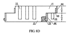
図8A、図8B、図8C、図8Dおよび図9乃至図11に示すように、延長ソケット11の反対側には、そのベースに沿って延長ソケット11の他方の側から延設される第3段差部45を形成する第3段差側壁を配置することができる。第3段差部45は、延長ソケット11と一体的に形成することができる。側部電気受け口48を、延長ソケット11の外装パネルに概ね面する第3段差部45の受け口配置壁に配置することができる。側部電気受け口48は、メイン電気受け口13に電気的に連結することができる。図示の実施形態では、側部電気受け口48は3ピンの電気受け口である。3ピンの電気受け口の3つの開口部は、第3段差部45の受け口配置壁に沿って一列に配置することができる。
As shown in FIGS. 8A, 8B, 8C, 8D, and 9 to 11, a third side extending from the other side of the
第2実施形態では、延長ソケット11を、他の延長ソケット11に接続することができる。接続するために、延長ソケット11の側部電気プラグ12は、他の延長ソケット11の側部電気受け口48に、そのベースに垂直な垂直方向に差し込まれる。延長ソケット11の側部電気プラグ12が他の延長ソケット11の側部電気受け口48に差し込まれると、延長ソケット11の逆向きの第2段差側壁が他の延長ソケット11の第3段差側壁と係合する。したがって、2つの接続される延長ソケット11は、容易には分離することができない。長手方向に延設される電源ストリップを形成する必要な場合、2つ以上の延長ソケット11を互いに接続できることは理解されよう。
In the second embodiment, the
同様に、第2段差側壁および第3段差側壁には、細長い突起および細長い溝を配置することができる。これにより、2つの延長ソケット11が分離するおそれを低減することができる。図示の実施形態では、2つの細長い突起19が第2段差側壁に配置され、一方、2つの細長い溝46が、第3段差側壁に配置される。
Similarly, elongated protrusions and elongated grooves can be disposed on the second step side wall and the third step side wall. Thereby, the possibility that the two
細長い突起が第2段差側壁に配置され、対応する細長い溝が第3段差側壁に配置される例を示し説明したが、細長い溝を第2段差側壁に配置し、対応する細長い突起を第3段差側壁に配置でき、あるいは細長い溝と突起を第2段差側壁に配置し、対応する細長い突起と溝を第3段差側壁に配置できることは理解されよう。 In the above description, the elongated protrusion is disposed on the second step side wall and the corresponding elongated groove is disposed on the third step side wall. However, the elongated groove is disposed on the second step side wall, and the corresponding elongated protrusion is disposed on the third step side wall. It will be appreciated that the elongated grooves and protrusions can be disposed on the second step sidewall and the corresponding elongated protrusions and grooves can be disposed on the third step sidewall.
留め具42を、延長ソケット11の第3段差側壁の垂直壁に形成することもできる。2つの延長ソケット11が互いに接続されるとき、留め具42は、延長ソケット11の第2段差側壁の垂直壁66に形成される対応する凹部23と係合する。留め具42は、外側に延設される位置に留め具42を付勢するための内部バネを有するバネ付勢留め具の態様とできる。
The
第2段差側壁および第3段差側壁が延長ソケット11の両側に形成される例を示し説明したが、第3段差側壁を第2段差側壁の隣接する側に配置することもできることは理解されよう。
Although the example in which the second step side wall and the third step side wall are formed on both sides of the
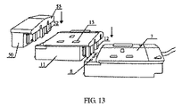
図12に示すように、電源ストリップは保護端部ピース50をさらに有することができる。保護端部ピース50は、外装パネルと、ベースと、その外装パネルに沿って延設される第4段差部55を形成する第4段差側壁と、を有することができる。保護端部ピース50には、電気受け口は配置されず、したがって、全体的に絶縁されている。
As shown in FIG. 12, the power strip can further include a
第4段差側壁は、第1段差側壁および第3段差側壁とは反転した形状で配置される。第4段差部55は、保護端部ピース50と一体的に形成することができる。側部プラグ52は、保護端部ピース50の外装パネルと反対に面するプラグ配置壁に配置することができる。図示の実施形態では、側部プラグ52は3ピンのプラグである。3つのピンは、保護端部ピース50のプラグ配置壁に沿って一列に配置することができる。これにより、側部プラグ52は、3つのピンが三角形状に配置される規格の3ピンの電気プラグと比較して、比較的横幅のない(フラットな)構成配置となる。保護端部ピース50は、電源コードソケット7の側部電気受け口8または延長ソケット11の側部電気受け口48へそのベースに垂直な方向に挿入可能である。これにより、保護端部ピース50の電源コードソケット7または延長ソケット11への接続の安定性を向上できる。保護端部ピース50は、また、電源ストリップの雷防護効果を与えるよう機能する。
The fourth step side wall is arranged in a shape inverted from the first step side wall and the third step side wall. The
図13に示すように、保護端部ピース50は、電源コードソケット7に接続されている複数の延長ソケット11のうちの最後の1つの延長ソケット11へ挿入することができる。このように形成される電源ストリップは、外観を一体的にでき、全体的に絶縁できる。
As shown in FIG. 13, the
同様に、保護端部ピース50の第4段差側壁は、保護端部ピース50を電源コードソケット7または延長ソケット11に保持するための係合要素を有するよう形成できる。
Similarly, the fourth step side wall of the
図14に示すように、延長ソケット11の留め具42または電源コードソケット7の留め具22を受けて係合するための凹部53を、保護端部ピース50のベースに垂直な第4段差側壁の垂直壁に形成することができる。
As shown in FIG. 14, a
さらに、保護端部ピース50を、摺動可能な係合によって電源コードソケット7または延長ソケット11に接続することができる。図14に示す例示の実施形態では、2つの垂直な細長い溝を、保護端部ピース50の外装パネルに垂直な第4段差側壁の第4段差部55の垂直壁に形成でき、そして2つの垂直な細長い突起59を、保護端部ピース50のベースに垂直な第4段差側壁の垂直壁に形成できる。これにより、保護端部ピース50の電源コードソケット7または延長ソケット11への接続を行うことができる。保護端部ピース50が電源コードソケット7または延長ソケット11に接続されると、係合溝および突起により保護端部ピース50が電源コードソケット7または延長ソケット11から分離するのを防止できる。保護端部ピース50を、保護端部ピース50と電源コードソケット7または延長ソケット11との間の溝・突起接続によって定位置にしっかりと保持することができるので、側部プラグ52を必ずしも保護端部ピース50に配置する必要がないことは理解されよう。
Furthermore, the
電源コードソケット7および延長ソケット11の電気接続は電気プラグと電気受け口とによって達成される例を示し説明したが、電源コードソケット7および延長ソケット11の電気接続は、電気金属ピン、プレート、ボス、スプリング、クリップなどあらゆる他の使用可能な電気接続によっても達成できることは当業者には理解されよう。
Although the electrical connection between the
電源コードソケット7、延長ソケット11および保護端部ピース50には、3ピンプラグおよび3ピン受け口が配置されている例を示し説明したが、電源コードソケット7、延長ソケット11および保護端部ピース50は、より多いピンまたはより少ないピンを有するプラグおよびソケットを配置できることは理解されよう。
The
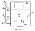
図15乃至図23は、電源コードソケット7、延長ソケット11および保護端部ピース50に、2ピンのプラグと2ピン受け口とが配置されている第4実施形態を示す。
15 to 23 show a fourth embodiment in which a 2-pin plug and a 2-pin receptacle are arranged in the
本願において開示した電源ストリップをいくつかの好ましい実施形態を特に参照して示し、説明したが、添付の実用新案請求の範囲から逸脱することなく種々の変形および変更を行うことができることを述べておく。 Although the power strip disclosed herein has been shown and described with particular reference to certain preferred embodiments, it is noted that various modifications and changes can be made without departing from the scope of the appended utility model claims. .
Claims (15)
(b)第2ソケットであって、外装パネルと、ベースと、該第2ソケットの外装パネルに沿って延設される第2段差部が形成されるとともに前記第1段差側壁とは反転した形状で該第2ソケットの一方の側に形成される第2段差側壁と、前記第2ソケットの外装パネルに配置されるメイン電気受け口と、前記第2段差側壁に配置されるとともに前記第2ソケットのメイン電気受け口に電気的に連結されており前記第1ソケットの第1電気コネクタに連結可能である第2電気コネクタと、を備える第2ソケットと、
を備える電源ストリップ。 (A) a first socket, an exterior panel, a base, a first step side wall in which a first step portion extending along the base is formed, and a main electrical receptacle disposed in the exterior panel A first electrical connector disposed on the first step side wall, and a first socket in which the main electrical receptacle and the first electrical connector are electrically connected to a power cord;
(B) a second socket, in which an exterior panel, a base, and a second step portion extending along the exterior panel of the second socket are formed and inverted from the first step sidewall The second step side wall formed on one side of the second socket, the main electric receptacle disposed on the exterior panel of the second socket, the second step side wall and the second step side wall of the second socket A second socket comprising: a second electrical connector electrically coupled to a main electrical receptacle and connectable to the first electrical connector of the first socket;
With power strip.
(a)電源コードと、
(b)第1ソケットであって、外装パネルと、ベースと、前記ベースに沿って延設される第1段差部が形成される第1段差側壁と、前記外装パネルに配置されるメイン電気受け口と、前記外装パネルと概ね同じ方向に面する前記第1段差部の受け口配置壁に配置される側部電気受け口と、を備え、前記メインおよび側部電気受け口が前記電源コードに電気的に連結されている第1ソケットと、
(c)第2ソケットであって、外装パネルと、ベースと、該第2ソケットの前記外装パネルに沿って延設される第2段差部が形成されるとともに前記第1段差側壁とは反転した形状で該第2ソケットの一方の側に形成される第2段差側壁と、前記第2ソケットの外装パネルに配置されるメイン電気受け口と、前記第2段差側壁に配置される側部プラグ該第2ソケットの外装パネルと反対に面する前記第2段差部のプラグ配置壁に配置される側部電気プラグと、を備え、該側部電気受け口が前記第2ソケットの前記メイン電気プラグに電気的に連結されている第2ソケットと、
を備えており、
(d)前記第2ソケットの側部電気プラグが前記第1ソケットの側部電気受け口へとベースに垂直な方向に挿入可能であり、これにより、第1および第2ソケットを互いに接続できる電源ストリップ。 A power strip composed of a plurality of connectable sockets,
(A) a power cord;
(B) a first socket, an exterior panel, a base, a first stepped side wall formed with a first stepped portion extending along the base, and a main electrical receptacle disposed in the exterior panel And a side electrical receptacle disposed on the receptacle arrangement wall of the first step portion facing substantially the same direction as the exterior panel, and the main and side electrical receptacles are electrically connected to the power cord A first socket being connected;
(C) a second socket, in which an exterior panel, a base, and a second step portion extending along the exterior panel of the second socket are formed and inverted from the first step sidewall. A second step side wall formed on one side of the second socket in shape, a main electrical receptacle disposed on the exterior panel of the second socket, and a side plug disposed on the second step side wall A side electric plug disposed on the plug arrangement wall of the second step portion facing the exterior panel of the two sockets, and the side electric receptacle is electrically connected to the main electric plug of the second socket. A second socket coupled to the
With
(D) a power strip that allows the side electrical plug of the second socket to be inserted into the side electrical receptacle of the first socket in a direction perpendicular to the base, thereby connecting the first and second sockets together; .
Applications Claiming Priority (3)
| Application Number | Priority Date | Filing Date | Title |
|---|---|---|---|
| CN200920244752.7U CN201508951U (en) | 2009-10-12 | 2009-10-12 | Connecting socket |
| CN200920244752.7 | 2009-10-12 | ||
| PCT/CN2010/076906 WO2011044804A1 (en) | 2009-10-12 | 2010-09-14 | Power strip |
Publications (1)
| Publication Number | Publication Date |
|---|---|
| JP3178924U true JP3178924U (en) | 2012-10-11 |
Family
ID=42470073
Family Applications (1)
| Application Number | Title | Priority Date | Filing Date |
|---|---|---|---|
| JP2012600041U Expired - Fee Related JP3178924U (en) | 2009-10-12 | 2010-09-14 | Power strip |
Country Status (6)
| Country | Link |
|---|---|
| US (1) | US8226444B2 (en) |
| EP (1) | EP2489102A4 (en) |
| JP (1) | JP3178924U (en) |
| CN (1) | CN201508951U (en) |
| HK (1) | HK1141943A2 (en) |
| WO (1) | WO2011044804A1 (en) |
Families Citing this family (15)
| Publication number | Priority date | Publication date | Assignee | Title |
|---|---|---|---|---|
| CN201508951U (en) * | 2009-10-12 | 2010-06-16 | 振兴实业发展有限公司 | Connecting socket |
| GB201121409D0 (en) * | 2011-12-13 | 2012-01-25 | Ifpl Group Ltd | User control interface |
| TWI527325B (en) * | 2012-07-02 | 2016-03-21 | 勝德國際研發股份有限公司 | Power extension cord with movable outlets |
| DE102012213258A1 (en) * | 2012-07-27 | 2014-01-30 | Siemens Aktiengesellschaft | connection system |
| DE202012010703U1 (en) * | 2012-11-09 | 2012-12-10 | Rosenberger Hochfrequenztechnik Gmbh & Co. Kg | Adapter with at least two adapter parts which can be connected to one another |
| CN104518325A (en) * | 2013-10-08 | 2015-04-15 | 能源立方国际有限公司 | Safety socketing structure of socket |
| US20150108841A1 (en) * | 2013-10-22 | 2015-04-23 | Studio Weber + Associates | Multifunctional power supply device |
| US9225102B1 (en) * | 2014-08-28 | 2015-12-29 | Pacific Star Communications, Inc. | Interconnection system for network modules |
| US9685730B2 (en) | 2014-09-12 | 2017-06-20 | Steelcase Inc. | Floor power distribution system |
| US10320136B2 (en) * | 2015-05-05 | 2019-06-11 | Rosenberger Hochfrequenztechnik Gmbh & Co. Kg | Adapter with at least two adapter parts which are connectable to one another |
| JP6458745B2 (en) * | 2016-02-18 | 2019-01-30 | オムロン株式会社 | Device unit |
| CN206022735U (en) | 2016-07-01 | 2017-03-15 | 吴文强 | Multi-function jack |
| US10199783B2 (en) | 2016-08-26 | 2019-02-05 | Valiant Innovations, LLC | Extendable modular power strip system and method of use |
| US10038272B2 (en) * | 2016-08-30 | 2018-07-31 | Western New England University | Flexible electrical power strip |
| DE202019100202U1 (en) * | 2019-01-15 | 2019-04-17 | Harbour Star International Ltd. | Modular system comprising electrical consumers and an electrical connection unit |
Family Cites Families (14)
| Publication number | Priority date | Publication date | Assignee | Title |
|---|---|---|---|---|
| US5094630A (en) * | 1991-02-25 | 1992-03-10 | Jammet Jean Claude | Multiple socket attachment |
| US5658158A (en) * | 1995-08-28 | 1997-08-19 | Milan; Henry | Modular surge protection system with interchangeable surge protection modules |
| US5885109A (en) * | 1997-10-16 | 1999-03-23 | Lee; Chiu-Shan | Electrical adapters |
| US6573617B2 (en) * | 1999-05-11 | 2003-06-03 | Fellowes Manufacturing Company | Modular power strip |
| CN2393234Y (en) * | 1999-10-15 | 2000-08-23 | 周义雄 | Stereo socket assembly |
| US20010027066A1 (en) * | 1999-12-20 | 2001-10-04 | Pit-Kin Loh | Modular power connector system |
| GB2376135B (en) * | 2001-05-30 | 2004-06-23 | Veronica Chapman | Extendable mains power feeding system |
| US7140922B2 (en) * | 2002-12-19 | 2006-11-28 | Pacusma Company, Ltd. | Multi-outlet AC/DC adapter |
| US6855007B2 (en) * | 2003-04-28 | 2005-02-15 | Illinois Tool Works Inc. | Switch connector and method |
| SG129318A1 (en) * | 2005-07-13 | 2007-02-26 | Copper Red Pte Ltd | Modular power distribution device |
| US7497740B2 (en) * | 2007-06-11 | 2009-03-03 | Tzu-Chiang Mei | Tandem-connected rotatable receptacle unit |
| FR2926930B1 (en) * | 2008-01-25 | 2010-04-02 | Legrand France | BASE OF ELECTRICAL APPARATUS AND ASSEMBLIES COMPRISING SAME |
| CN201282253Y (en) * | 2008-09-28 | 2009-07-29 | 黄养平 | Multifunctional socket and plug |
| CN201508951U (en) * | 2009-10-12 | 2010-06-16 | 振兴实业发展有限公司 | Connecting socket |
-
2009
- 2009-10-12 CN CN200920244752.7U patent/CN201508951U/en not_active Expired - Fee Related
-
2010
- 2010-07-27 HK HK10107171.4A patent/HK1141943A2/en not_active IP Right Cessation
- 2010-09-14 WO PCT/CN2010/076906 patent/WO2011044804A1/en active Application Filing
- 2010-09-14 JP JP2012600041U patent/JP3178924U/en not_active Expired - Fee Related
- 2010-09-14 EP EP10823034.3A patent/EP2489102A4/en not_active Withdrawn
- 2010-09-17 US US12/884,223 patent/US8226444B2/en not_active Expired - Fee Related
Also Published As
| Publication number | Publication date |
|---|---|
| US8226444B2 (en) | 2012-07-24 |
| EP2489102A4 (en) | 2013-05-22 |
| CN201508951U (en) | 2010-06-16 |
| EP2489102A1 (en) | 2012-08-22 |
| WO2011044804A1 (en) | 2011-04-21 |
| HK1141943A2 (en) | 2010-11-19 |
| US20110086542A1 (en) | 2011-04-14 |
Similar Documents
| Publication | Publication Date | Title |
|---|---|---|
| JP3178924U (en) | Power strip | |
| US20150201762A1 (en) | Suspension Device For Presenting Goods, Having A Current-Carrying Profiled Rail And Primary Support Which Can Be Hung Therein | |
| JP4915975B2 (en) | DC outlet | |
| CN103972741A (en) | Waterproof and anti-electric-shock socket and power strip thereof | |
| KR101484010B1 (en) | Energy-saving power strip | |
| CN203826715U (en) | Waterproof anti-electric shock socket and power strip thereof | |
| US20120171891A1 (en) | Plug | |
| US20230163543A1 (en) | Replaceable Socket Device and Adapter | |
| CN215528031U (en) | Detachable socket | |
| JP5336975B2 (en) | DC outlet | |
| JP5330926B2 (en) | Plug | |
| JP2012185988A (en) | Plug, outlet, luminaire, and show case | |
| CN203690581U (en) | Wall in type socket | |
| JP5351697B2 (en) | Wiring device | |
| JP5330948B2 (en) | Plug | |
| JP3085686U (en) | Multi-directional outlet | |
| CN218242487U (en) | External hanging movable socket adaptive to power supply track | |
| CN202903824U (en) | Lamp holder structure for LED tube aging test | |
| KR101973090B1 (en) | Multi-stage prefabricated outlet | |
| CN216850468U (en) | Wall socket | |
| CN216598226U (en) | Electrical connector and panel light assembly | |
| CN210608415U (en) | Concealed wiring box | |
| CN217589657U (en) | Embedded socket and have its home equipment | |
| US20180316118A1 (en) | An electrical power outlet strip | |
| CN212626314U (en) | Electric socket for building |
Legal Events
| Date | Code | Title | Description |
|---|---|---|---|
| R150 | Certificate of patent or registration of utility model |
Free format text: JAPANESE INTERMEDIATE CODE: R150 |
|
| FPAY | Renewal fee payment (event date is renewal date of database) |
Free format text: PAYMENT UNTIL: 20150919 Year of fee payment: 3 |
|
| R250 | Receipt of annual fees |
Free format text: JAPANESE INTERMEDIATE CODE: R250 |
|
| R250 | Receipt of annual fees |
Free format text: JAPANESE INTERMEDIATE CODE: R250 |
|
| LAPS | Cancellation because of no payment of annual fees |