JP3174635U - Lighting device - Google Patents
Lighting device Download PDFInfo
- Publication number
- JP3174635U JP3174635U JP2012000217U JP2012000217U JP3174635U JP 3174635 U JP3174635 U JP 3174635U JP 2012000217 U JP2012000217 U JP 2012000217U JP 2012000217 U JP2012000217 U JP 2012000217U JP 3174635 U JP3174635 U JP 3174635U
- Authority
- JP
- Japan
- Prior art keywords
- led
- light source
- lighting device
- columnar
- movable
- Prior art date
- Legal status (The legal status is an assumption and is not a legal conclusion. Google has not performed a legal analysis and makes no representation as to the accuracy of the status listed.)
- Expired - Fee Related
Links
Images


Landscapes
- Non-Portable Lighting Devices Or Systems Thereof (AREA)
- Arrangement Of Elements, Cooling, Sealing, Or The Like Of Lighting Devices (AREA)
Abstract
【課題】第一光源によって任意の領域を局所的に照射すると共に、第二光源によって広い範囲を照射することができる照明装置を提供する。
【解決手段】柱状部9に対し可動部10を揺動可能に設けて構成される照明装置本体3を有し、可動部10に第一光源としての第一LEDを設けた照明装置であって、柱状部9に第二光源としての第二LEDを設けると共に、可動部10全体を、前記第二LEDの光軸Lよりも軸直方向に偏位させた位置に常時配置したことで、可動部10を揺動させ、前記第一LEDによって任意の領域を局所的に照射することができると共に、可動部10の姿勢に拘わらず、前記第二LEDによって、部屋の広い範囲を間接照明することができる。
【選択図】図9An illumination device capable of locally irradiating an arbitrary region with a first light source and irradiating a wide range with a second light source.
An illuminating device having an illuminating device main body 3 configured by swingably providing a movable portion 10 with respect to a columnar portion 9 and provided with a first LED as a first light source on the movable portion 10. The columnar portion 9 is provided with a second LED as a second light source, and the entire movable portion 10 is always disposed at a position displaced in a direction perpendicular to the optical axis L of the second LED. The unit 10 can be swung and an arbitrary region can be locally irradiated by the first LED, and a wide range of the room can be indirectly illuminated by the second LED regardless of the posture of the movable unit 10. Can do.
[Selection] Figure 9
Description
本考案は、柱状部に対して揺動可能な可動部に光源を設けた照明装置に関するものである。 The present invention relates to an illuminating device in which a light source is provided on a movable part that can swing with respect to a columnar part.
従来、この種の照明装置は、載置部と、この載置部から上方に延びる支持部と、この支持部に取り付けられる灯体とを有して構成され、この灯体に、光源部と補助光源と充電部を設けたものが知られている(例えば、特許文献1参照。)。そして、平常時には、外部電力によって前記光源部を点灯させると共に、停電時には、前記充電部の電力によって、前記補助光源を点灯させることができる。また、前記支持部から前記灯体を取り外すことで、この灯体を懐中電灯として使用することもできる。 Conventionally, this type of lighting device is configured to include a mounting portion, a support portion that extends upward from the mounting portion, and a lamp body that is attached to the support portion. What provided the auxiliary light source and the charge part is known (for example, refer patent document 1). In normal times, the light source unit can be turned on by external power, and at the time of a power failure, the auxiliary light source can be turned on by the power of the charging unit. Moreover, this lamp body can also be used as a flashlight by removing the lamp body from the support portion.
しかしながら、特許文献1のような照明装置は、前記充電部が前記灯体に収容されるため、この灯体が重くなってしまう。従って、この灯体を揺動させて任意の方向を照射することが困難であるという問題があった。また、特許文献1のような照明装置は、前記補助光源が横向きであるため、照明装置を使用している部屋に置かれた物体等が障害物となって室内を良好に照明できない虞がある。即ち、停電時、前記補助光源が点灯し、照明装置の在処が判ったとしても、使用者から照明装置までの間に障害物があるか判りにくく、危険である。更に、前記灯体を懐中電灯として使用する場合、前記灯体を持ち運ぶ際に前記光源部を覆うLEDカバーが破損する虞もあった。
However, in the lighting device as disclosed in
本考案は以上の問題点を解決し、第一光源によって任意の領域を局所的に照射すると共に、第二光源によって広い範囲を照射することができる照明装置を提供することを目的とする。 An object of the present invention is to solve the above problems, and to provide an illumination device that can irradiate an arbitrary region locally with a first light source and irradiate a wide range with a second light source.
本考案の請求項1に記載の照明装置は、柱状部に対し可動部を揺動可能に設けて構成される照明装置本体を有し、前記可動部に第一光源を設けた照明装置において、前記柱状部に第二光源を設けると共に、前記可動部全体を、前記第二光源の光軸よりも軸直方向に偏位させた位置に常時配置したものである。
The lighting device according to
また、本考案の請求項2に記載の照明装置は、請求項1において、前記第二光源を、前記柱状部の先端に設けたものである。
According to
また、本考案の請求項3に記載の照明装置は、請求項1において、前記第二光源の光軸を垂直としたものである。
According to
また、本考案の請求項4に記載の照明装置は、請求項2において、前記第二光源を、前記柱状部の上端に設けたものである。 According to a fourth aspect of the present invention, in the lighting device according to the second aspect, the second light source is provided at an upper end of the columnar portion.
また、本考案の請求項5に記載の照明装置は、請求項1から4の何れか一項において、前記照明装置本体を、外部電源に接続される基部に対し着脱可能に接続すると共に、前記柱状部に電池を収容したものである。
Moreover, the lighting device according to
更に、本考案の請求項6に記載の照明装置は、請求項5において、前記可動部を畳んだ際に、前記柱状部と対向する位置に、前記第一光源が設けられるものである。
Furthermore, the lighting device according to claim 6 of the present invention is the lighting device according to
本考案の請求項1に記載の照明装置は、以上のように構成することにより、前記可動部を揺動させ、前記第一光源によって任意の領域を局所的に照射することができる。また、前記第二光源を用いて、部屋の広い範囲を間接照明することができる。この際、前記可動部が前記第二光源の光軸と重ならないので、前記可動部の姿勢によらず、部屋の広い範囲を間接照明することができる。
The illumination device according to
なお、前記第二光源を、前記柱状部の先端に設ければ、前記柱状部自体の影も出来にくくなるので、前記第二光源による照明をより良好に行うことができる。 If the second light source is provided at the tip of the columnar part, the columnar part itself is less likely to be shaded, so that the illumination by the second light source can be performed better.
また、前記第二光源の光軸を垂直とすれば、前記第二光源の光を部屋の天井に当てて、部屋の広い範囲を間接照明することができる。 Further, if the optical axis of the second light source is vertical, the light of the second light source can be applied to the ceiling of the room to indirectly illuminate a wide area of the room.
また、前記第二光源を、前記柱状部の上端に設ければ、前記柱状部自体の影も出来にくくなるので、前記第二光源による照明をより良好に行うことができる。 Further, if the second light source is provided at the upper end of the columnar part, it is difficult to make a shadow of the columnar part itself, so that the illumination by the second light source can be performed better.
また、前記照明装置本体を、外部電源に接続される基部に対し着脱可能に接続すると共に、前記柱状部に電池を収容すれば、前記可動部を重くすることなく、この可動部を揺動させて任意の領域を局所的に照射することができるばかりでなく、前記照明装置本体を前記基部から取り外すことで、前記第二光源を発光させる懐中電灯として使用することもできる。 Further, when the lighting device main body is detachably connected to a base connected to an external power source and a battery is accommodated in the columnar portion, the movable portion is swung without increasing the weight of the movable portion. In addition to being able to irradiate an arbitrary region locally, it can also be used as a flashlight that emits light from the second light source by removing the lighting device body from the base.
更に、前記可動部を畳んだ際に、前記柱状部と対向する位置に前記第一光源を設ければ、前記照明装置本体を持ち運ぶ際等に、前記第一光源を破損させる虞を減少させることができる。 Furthermore, when the first light source is provided at a position facing the columnar part when the movable part is folded, the possibility of damaging the first light source when carrying the lighting device body is reduced. Can do.
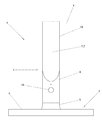
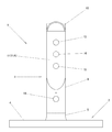
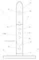
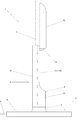
以下、本考案の実施形態について、図1乃至図11に基づいて説明する。なお、以下の説明において、図1乃至図10の姿勢を基準として、前後を規定する。即ち、図2、図5、図8において、下方が前、上方が後である。また、図3、図6、図9において、右側が前、左側が後である。1は本考案の照明装置である。この照明装置1は、基部2と照明装置本体3から構成される。なお、前記照明装置本体3は、前記基部2に対し着脱可能に取り付けられる。
Hereinafter, embodiments of the present invention will be described with reference to FIGS. 1 to 11. In the following description, front and rear are defined based on the postures of FIGS. That is, in FIGS. 2, 5, and 8, the lower side is the front and the upper side is the rear. 3, 6, and 9, the right side is the front and the left side is the rear.
前記基部2は、円盤部4と、この円盤部4の中央に設けられた、略短円筒状の接続部5と、電源ケーブル6とを有する。なお、この電源ケーブル6は、前記接続部5に設けられた給電端子7に接続される。また、前記電源ケーブル6の先端には、交流/直流変換器8が設けられる。なお、この交流/直流変換器8は、前記基部2内に収容しても良い。
The
前記照明装置本体3は、柱状部9と可動部10を有する。前記柱状部9は、円筒形状の上部の前半部を切り欠いた形状である。前記柱状部9の切欠部11の上端部には、腕部12が前方に伸びて形成され、この腕部12に前記可動部10が揺動可能に取り付けられる。なお、前記可動部10の揺動軸Xは、前記照明装置本体3を前記基部2に取り付けた状態において、水平に延びる。また、前記揺動軸Xは、正面視で左右に延びる。前記柱状部9の切欠部11には、切替操作部13、調光操作部14、及びタイマー操作部15が設けられる。前記切替操作部13は、第一光源としての第一LED16と第二光源としての第二LED17を切り替えるためのものである。また、前記調光操作部14は、前記第一LED16又は第二LED17の明るさを調整するためのものである。また、前記タイマー操作部15は、前記第一LED16又は第二LED17をオフタイマー操作するためのものである。なお、これらの操作部13,14,15は、前記可動部10を畳んだ際に、この可動部10によって覆われる。また、前記柱状部9の下部正面には、主操作部18が設けられる。この主操作部18は、前記切替操作部13によって選択された前記第一LED16又は第二LED17を点灯又は消灯させるためのものである。なお、前記主操作部18は、常時露出する。そして、前記柱状部9の上端部には、レンズ19を介して前記第二LED17が光学的に露出する。この第二LED17は、前記揺動軸X及び前記切欠部11の前面11Aよりも後方に位置する。なお、前記第二LED17の光軸Lは、垂直に延びる。また、前記柱状部9の下端部には、複数の受電端子20が設けられ、これらの受電端子20が前記給電端子7と電気的に接続される。なお、21は前記柱状部9の後部に設けられた電池蓋、22は前記柱状部9内に収容された電池である。なお、電池22としては、乾電池の他、乾電池型の二次電池を用いても良い。
The
前記可動部10は、この可動部10を畳んだ状態で前記照明装置本体3が円筒状となるように、前記柱状部9の切欠部11を補完する形状に形成される。即ち、前記可動部10を畳んだ状態において、前記照明装置本体3は円筒状となる。そして、前記基部2に前記照明装置本体3を取り付けた状態において、前記接続部5の中心軸Yと前記照明装置本体3の中心軸Zは一致する。即ち、前記照明装置本体3は、前記接続部5に対し同軸状に取り付けられる。そして、前記照明装置本体3は、中心軸Y,Z回りに回動可能である。また、前記第二LED17の光軸Lは、前記照明装置本体3の中心軸Zと平行であると共に、この中心軸Zよりも後方に偏位する。更に、前記可動部10には、前記第一LED16が設けられる。この第一LED16は、散光板23を介して光学的に露出する。そして、前記第一LED16及び散光板23は、前記可動部10を畳んだ状態において、前記切欠部11の前面11Aと対向する。なお、前記可動部10は、姿勢によらず、前記切欠部11の前面11Aよりも前方に位置する。即ち、前記可動部10は、前記第二LED17の光軸L上に位置することがない。
The
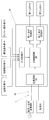
図11は、照明装置1の回路のブロック図を示すものである。この図11において、24は制御回路である。この制御回路24は、主制御回路25と、電源回路26と、入力回路27と、第一点灯回路28と第二点灯回路29を有する。前記電源回路26は、前記交流/直流変換器8又は電池22からの電力を前記第一LED16又は第二LED17に供給するためのものである。また、前記入力回路27は、前記各操作部13,14,15,18の操作を検知し、前記主制御回路25に入力するためのものである。また、前記第一点灯回路28は、前記第一LED16を点灯させるためのものである。更に、前記第二点灯回路29は、前記第二LED17を点灯させるためのものである。
FIG. 11 shows a block diagram of a circuit of the
次に、本実施形態の作用について説明する。まず使用者は、前記照明装置本体3を前記基部2に取り付け、前記給電端子7と受電端子20を接続した後、前記電源ケーブル6の先端に設けられた前記交流/直流変換器8を交流電源に接続する。この状態で、前記主操作部18を操作することで、前記第一LED16又は第二LED17を点灯させることができる。
Next, the operation of this embodiment will be described. First, the user attaches the
前記第一LED14を点灯させる場合、前記可動部8を揺動軸X回りに回動させると共に前記柱状部7を中心軸Y,Z回りに回動させて、前記第一LED14を任意の方向に向けた後、前記主操作部18を操作し、必要に応じ前記切替操作部13を操作する。これらの操作により、前記第一LED14は、前記交流/直流変換器から電力が供給されて点灯する。なお、前記制御回路24は、前記第一LED16と第二LED17の何れが最後に点灯したかを記憶することができる。このため、最後に点灯させたLEDが前記第一LED16であれば、前記切替操作部13を操作する必要がない。逆に、最後に点灯させたLEDが前記第二LED17であれば、前記切替操作部13を操作する必要がある。そして、前記第一LED16が点灯すると、この第一LED16から放射された光は、前記散光板23によって拡散される。この拡散板23で拡散された光によって、任意の照射領域が局所的に照射される。なお、前記照射領域は、前記散光板23で拡散された光によって照射されるので、眩しさが低減される。そして、前記第一LED16は、前記調光操作部14を操作することによって、明るさを調節することができる。また、前記第一LED16は、前記タイマー操作部15を操作することによって、所定時間経過後に消灯させることができる。
When the
前記第二LED17を点灯させる場合、前記主操作部18を操作した後、必要に応じ前記切替操作部13を操作する。なお、前述した通り、前記制御回路24は、前記第一LED16と第二LED17の何れが最後に点灯したかを記憶することができる。このため、最後に点灯させたLEDが前記第一LED16であれば、前記切替操作部13を操作する必要がある。逆に、最後に点灯させたLEDが前記第二LED17であれば、前記切替操作部13を操作する必要がない。そして、前記第二LED17が点灯すると、この第二LED17から放射された光は、前記レンズ19によって集光される。また、前記第二LED17の光軸Lは、前記照明装置本体3を前記基部2に取り付けた状態において、垂直となる。即ち、前記柱状部9の上端部に設けられた前記第二LED17から放射された光は、上向きに放出される。このため、前記第二LED17から放射された光は、部屋の天井を照射した後、この天井において拡散反射され、部屋の広い範囲を照射する。なお、前記第二LED17も、前記第一LED16と同様に、前記調光操作部14を操作することによって、明るさを調節することができる。また、前記第二LED17も、前記第一LED16と同様に、前記タイマー操作部15を操作することによって、所定時間経過後に消灯させることができる。
When the
なお、前述した通り、前記第二LED17は、前記柱状部9の上端部に設けられていると共に、前記可動部10全体が光軸L上に重ならないように配置される。このため、前記第二LED17から放射された光は、前記可動部10の姿勢によらず、この可動部10、或いは前記柱状部9自体によって遮られることがない。また、前記第二LED17は、光を上向きに放射するので、一般的な使用では、部屋に置いた物体が、光を天井に照射する際の障害となる虞が少ない。従って、前記第二LED17によって、室内を良好に間接照明することができる。
As described above, the
なお、停電等により、前記交流/直流変換器7からの電力が断たれると、これを前記電源回路26が検知する。この際、この電源回路26は、前記電池22の電力を、前記制御回路24全体に供給する。このようにして停電が検知されると、前記主制御回路25は、前記電池22からの電力を、第二点灯回路29介して前記第二LED17に供給し、この第二LED17を弱モードで発光させる。なお、前記制御回路24は、停電等が発生する前に何れのLED16,17も点灯させていなくても、或いは前記第一LED16を点灯させていた場合であっても、停電等が発生すると、前記第二LED17を点灯させる。そして、上述した通り、前記第二LED17が光を上向きに放射して天井を照射するので、室内は、前記第二LED17によって間接照明される。そして、前記第二LED17から放射された光が、前記柱状部9自体や可動部10に遮られることなく、また、室内に置かれた物体に遮られる虞も少ないので、薄暗くではあるが、室内は確実に照明される。このため、停電等で室内の他の照明が消えた状態となり、本願発明の前記照明装置1のみによって室内が照明される状態となっても、室内を確実に照明することができる。そして、室内が確実に照明されることで、室内に置かれた物体を視認可能となる。これによって、使用者が室内を移動する際に、室内に置かれた物体によって怪我をする虞を減ずることができる。なお、何も操作しなければ、前記第二LED17は、所定時間経過後に消灯する。
When the power from the AC / DC converter 7 is cut off due to a power failure or the like, the
また、このように停電等によって室内の他の照明が失われた際に、前記照明装置1の照明装置本体3を前記基部2から取り外して、懐中電灯として使用することも可能である。この場合、前述した通り、前記可動部10が前記柱状部9の切欠部11を補完する形状であるため、前記可動部10を折り畳むことで、前記照明装置本体3は円筒状となる。そして、前記可動部10を折り畳むと、前記切替操作部13、調光操作部14、タイマー操作部15は、前記可動部10によって覆い隠される。また、前記第一LED16及び散光板23は、前記柱状部9によって覆い隠される。従って、前記照明装置本体3を持ち運ぶ際に、不用意に各操作部13,14,15を操作してしまったり、前記散光板23を破損してしまったりする虞を減ずることができる。なお、前述した通り、前記第二LED17は弱モードで発光するので、懐中電灯として使用するには暗すぎる。このため、使用者は、前記調光操作部14を操作して、前記第二LED17を強モードで発光させる。このように、前記操作部13,14,15のうちの何れかを操作すると、タイマーが解除される。なお、前記制御回路24は、前記照明装置本体3を前記基部2から取り外すことで、前記交流/直流変換器7からの電力が断たれた場合であっても、停電時と同様に作動する。
In addition, when other lighting in the room is lost due to a power failure or the like, the
以上のように本考案の照明装置1は、柱状部9に対し可動部10を揺動可能に設けて構成される照明装置本体3を有し、前記可動部9に第一光源としての第一LED16を設けた照明装置であって、前記柱状部9に第二光源としての第二LED17を設けると共に、前記可動部10全体を、前記第二LED17の光軸Lよりも軸直方向に偏位させた位置に常時配置したことで、前記可動部10を揺動させ、前記第一LED16によって任意の領域を局所的に照射することができると共に、前記可動部10の姿勢に拘わらず、前記第二LED17によって、部屋の広い範囲を間接照明することができるものである。
As described above, the illuminating
また、本考案の照明装置1は、前記第二LED17を、前記柱状部9の先端に設けたことで、前記柱状部9自体の影も出来にくくして、前記第二LED17による照明をより良好に行うことができるものである。
In addition, the
また、本考案の照明装置1は、前記第二LED17の光軸Lを垂直としたことで、前記第二LED17の光を部屋の天井に当てて、部屋の広い範囲を間接照明することができるものである。
Moreover, the
また、本考案の照明装置1は、前記第二LED17を、前記柱状部9の上端に設けたことで、前記柱状部9自体の影も出来にくくして、前記第二LED17による照明をより良好に行うことができるものである。
Further, the
また、本考案の照明装置1は、前記照明装置本体3を、外部電源に接続される基部2に対し着脱可能に接続すると共に、前記柱状部9に電池22を収容したことで、前記可動部10を重くすることなく、この可動部10を揺動させて任意の領域を局所的に照射することができるばかりでなく、前記照明装置本体3を前記基部2から取り外すことで、前記第二LED17を発光させる懐中電灯として使用することもできるものである。
In addition, the
更に、本考案の照明装置1は、前記可動部10を畳んだ際に、前記柱状部9と対向する位置に前記第一LED16を設けたことで、前記照明装置本体3を持ち運ぶ際等に、前記第一LED16やこれを覆う散光板23を破損させる虞を減少させることができるものである。
Furthermore, when the
なお、本考案は以上の実施形態に限定されるものではなく、考案の要旨の範囲内で種々の変形実施が可能である。例えば、上記実施形態では、可動部が一つの揺動軸回りにのみ揺動可能であるが、揺動軸を複数設けたり、ボールジョイント等によって自在に揺動させることができるようにしたりしても良い。この場合であっても、前記可動部は、前記第二光源の光軸とは重ならないようにする必要がある。また、上記実施形態では、各光源はLEDであるが、LED以外の光源を用いても良い。 In addition, this invention is not limited to the above embodiment, A various deformation | transformation implementation is possible within the range of the summary of invention. For example, in the above-described embodiment, the movable part can swing only around one swinging shaft, but a plurality of swinging shafts can be provided or freely swingable by a ball joint or the like. Also good. Even in this case, it is necessary that the movable portion does not overlap the optical axis of the second light source. Moreover, in the said embodiment, although each light source is LED, you may use light sources other than LED.
1 照明装置
2 基部
3 照明装置本体
9 柱状部
10 可動部
16 第一LED(第一光源)
17 第二LED(第二光源)
22 電池
L 光軸
DESCRIPTION OF
17 Second LED (second light source)
22 Battery L Optical axis
Claims (6)
前記柱状部に第二光源を設けると共に、前記可動部全体を、前記第二光源の光軸よりも軸直方向に偏位させた位置に常時配置したことを特徴とする照明装置。 In an illuminating device having an illuminating device main body configured to be swingable with respect to a columnar portion, and provided with a first light source in the movable portion,
A lighting device characterized in that a second light source is provided in the columnar part, and the entire movable part is always disposed at a position displaced in a direction perpendicular to the optical axis of the second light source.
Priority Applications (2)
| Application Number | Priority Date | Filing Date | Title |
|---|---|---|---|
| JP2012000217U JP3174635U (en) | 2012-01-18 | 2012-01-18 | Lighting device |
| CN 201320025317 CN203052480U (en) | 2012-01-18 | 2013-01-17 | Lighting device |
Applications Claiming Priority (1)
| Application Number | Priority Date | Filing Date | Title |
|---|---|---|---|
| JP2012000217U JP3174635U (en) | 2012-01-18 | 2012-01-18 | Lighting device |
Publications (1)
| Publication Number | Publication Date |
|---|---|
| JP3174635U true JP3174635U (en) | 2012-03-29 |
Family
ID=48001756
Family Applications (1)
| Application Number | Title | Priority Date | Filing Date |
|---|---|---|---|
| JP2012000217U Expired - Fee Related JP3174635U (en) | 2012-01-18 | 2012-01-18 | Lighting device |
Country Status (2)
| Country | Link |
|---|---|
| JP (1) | JP3174635U (en) |
| CN (1) | CN203052480U (en) |
Cited By (4)
| Publication number | Priority date | Publication date | Assignee | Title |
|---|---|---|---|---|
| JP2015008082A (en) * | 2013-06-25 | 2015-01-15 | 株式会社岡村製作所 | Power supply device |
| CN104952120A (en) * | 2014-03-24 | 2015-09-30 | 比亚迪股份有限公司 | Vehicle information notification system and vehicle information notification method |
| JP2020177894A (en) * | 2019-04-18 | 2020-10-29 | 青島欧昇灯具有限公司 | Desktop multifunction LED light |
| JP2020194750A (en) * | 2019-05-30 | 2020-12-03 | 株式会社イトーキ | Lighting tool and furniture |
-
2012
- 2012-01-18 JP JP2012000217U patent/JP3174635U/en not_active Expired - Fee Related
-
2013
- 2013-01-17 CN CN 201320025317 patent/CN203052480U/en not_active Expired - Fee Related
Cited By (5)
| Publication number | Priority date | Publication date | Assignee | Title |
|---|---|---|---|---|
| JP2015008082A (en) * | 2013-06-25 | 2015-01-15 | 株式会社岡村製作所 | Power supply device |
| CN104952120A (en) * | 2014-03-24 | 2015-09-30 | 比亚迪股份有限公司 | Vehicle information notification system and vehicle information notification method |
| CN104952120B (en) * | 2014-03-24 | 2018-03-27 | 比亚迪股份有限公司 | Vehicle information notification system and vehicle information notification method |
| JP2020177894A (en) * | 2019-04-18 | 2020-10-29 | 青島欧昇灯具有限公司 | Desktop multifunction LED light |
| JP2020194750A (en) * | 2019-05-30 | 2020-12-03 | 株式会社イトーキ | Lighting tool and furniture |
Also Published As
| Publication number | Publication date |
|---|---|
| CN203052480U (en) | 2013-07-10 |
Similar Documents
| Publication | Publication Date | Title |
|---|---|---|
| JP3174635U (en) | Lighting device | |
| JP2014239069A (en) | Lighting device and method for fire fighter | |
| JP2015185454A5 (en) | ||
| BRPI0924896B1 (en) | ELECTRICAL INSTALLATION | |
| JP2007335282A (en) | Lighting device | |
| KR20180024597A (en) | Smart energy-saiving stand using automatic lighting control | |
| JPH1034566A (en) | Illuminated power tool | |
| JP2009193887A (en) | Lighting device | |
| JP2018142473A (en) | lighting equipment | |
| CN102313144A (en) | The hand-held lighting apparatus | |
| CN114576576A (en) | Multi-panel lighting device | |
| CN109745173A (en) | Auto-darkening welding mask | |
| WO2022161038A1 (en) | Workbench | |
| KR20090010868U (en) | Stand combined power supply sleep light | |
| JP5864536B2 (en) | LED lighting device | |
| JP2011206339A (en) | Charging type vacuum cleaner | |
| JP2022070142A (en) | Illuminating device | |
| CN211203856U (en) | Lighting system of optical fiber fusion splicer | |
| US20070236961A1 (en) | Night light | |
| CN202056556U (en) | Improved portable searchlight | |
| CN205278925U (en) | Vehicle and lighting components who is used for vehicle | |
| JP3144332U (en) | LED black light | |
| JP3163865U (en) | LED guide light | |
| KR101416987B1 (en) | A Skin Treatment Apparatus Using LED System | |
| EP1521031A2 (en) | Light emitting diode lighting appliance and light emitting diode emergency light using the same |
Legal Events
| Date | Code | Title | Description |
|---|---|---|---|
| R150 | Certificate of patent or registration of utility model |
Ref document number: 3174635 Country of ref document: JP Free format text: JAPANESE INTERMEDIATE CODE: R150 Free format text: JAPANESE INTERMEDIATE CODE: R150 |
|
| FPAY | Renewal fee payment (event date is renewal date of database) |
Free format text: PAYMENT UNTIL: 20150307 Year of fee payment: 3 |
|
| R250 | Receipt of annual fees |
Free format text: JAPANESE INTERMEDIATE CODE: R250 |
|
| R250 | Receipt of annual fees |
Free format text: JAPANESE INTERMEDIATE CODE: R250 |
|
| R250 | Receipt of annual fees |
Free format text: JAPANESE INTERMEDIATE CODE: R250 |
|
| R250 | Receipt of annual fees |
Free format text: JAPANESE INTERMEDIATE CODE: R250 |
|
| LAPS | Cancellation because of no payment of annual fees |