JP2011206339A - Charging type vacuum cleaner - Google Patents
Charging type vacuum cleaner Download PDFInfo
- Publication number
- JP2011206339A JP2011206339A JP2010078181A JP2010078181A JP2011206339A JP 2011206339 A JP2011206339 A JP 2011206339A JP 2010078181 A JP2010078181 A JP 2010078181A JP 2010078181 A JP2010078181 A JP 2010078181A JP 2011206339 A JP2011206339 A JP 2011206339A
- Authority
- JP
- Japan
- Prior art keywords
- illumination
- cleaner
- function
- rechargeable
- fluorescent lamp
- Prior art date
- Legal status (The legal status is an assumption and is not a legal conclusion. Google has not performed a legal analysis and makes no representation as to the accuracy of the status listed.)
- Pending
Links
Images
Landscapes
- Electric Vacuum Cleaner (AREA)
Abstract
【課題】ハンディタイプ掃除機としての機能を有しつつ照明装置が配設される充電式クリーナにおいて、照明の使用目的に応じて使用目的に合致した照明方法を選択できるようにする。
【解決手段】照明装置40は、照明の機能目的が互いに相違する、LED45を用いて照明する発光ダイオード照明機能(LED照明部41)と、蛍光灯55を用いて照明する蛍光灯照明機能(蛍光灯照明部51)と、の2種類の照明機能を備える。このため、LED照明部41を利用して常備灯のようにスポット的に照らし出すようにしたり、蛍光灯照明部51を利用して近傍周囲を広範囲で照らし出すようにしたりすることができる。また、コントローラ65は、単独スイッチ66、切替スイッチ67、操作トリガ24からの操作入力に応じて、送風機22、LED45、蛍光灯55のいずれかを選択してオンオフ動作の制御をしている。
【選択図】図1In a rechargeable cleaner that has a function as a handy type vacuum cleaner and in which an illumination device is provided, an illumination method that matches the purpose of use can be selected according to the purpose of use of the illumination.
A lighting device includes a light emitting diode illumination function (LED illumination unit) that illuminates using an LED and a fluorescent lamp illumination function that illuminates using a fluorescent lamp. Lamp illumination unit 51) and two types of illumination functions. For this reason, the LED illumination unit 41 can be used to illuminate the spot like a standing lamp, or the fluorescent lamp illumination unit 51 can be used to illuminate the vicinity in a wide range. In addition, the controller 65 selects one of the blower 22, the LED 45, and the fluorescent lamp 55 in accordance with operation inputs from the single switch 66, the changeover switch 67, and the operation trigger 24, and controls the on / off operation.
[Selection] Figure 1
Description
本発明は、ハンディタイプ掃除機としての機能を有しつつ照明装置が配設される充電式クリーナに関する。 The present invention relates to a rechargeable cleaner that has a function as a handy type vacuum cleaner and in which an illumination device is disposed.
従来、いわゆるハンディタイプ掃除機として分類される充電式クリーナが知られている。このような充電式クリーナは、充電式電池を具備して構成され、不使用時に充電し、使用時にコードレス状態で使用することができるようになっている。
ところで、このような充電式クリーナにあっては、このようなハンディタイプ掃除機の機能のほか、照明灯の機能を付属するものが知られている(例えば、特許文献1、特許文献2参照)。このような照明灯の機能を付属する充電式クリーナによれば、ハンディタイプ掃除機として利用しつつ、照明灯としても利用することができて、利便性の高い充電式クリーナとなる。
Conventionally, a rechargeable cleaner classified as a so-called handy type vacuum cleaner is known. Such a rechargeable cleaner includes a rechargeable battery, and can be charged when not in use and used in a cordless state when in use.
By the way, in such a rechargeable cleaner, what attaches the function of an illuminating lamp other than the function of such a handy type vacuum cleaner is known (for example, refer to patent documents 1 and patent documents 2). . According to the rechargeable cleaner attached with the function of such an illuminating lamp, it can be used as an illuminating lamp while being used as a handy type vacuum cleaner, and it becomes a highly convenient rechargeable cleaner.
しかしながら、昨今の照明方法としては、照明の使用目的に応じて多様化しつつある。すなわち、昨今の照明方法には、いわゆる常備灯のようにスポット的に照らし出す照明方法や、近傍周囲を広範囲で照らし出す照明方法等がある。このため、使用者の照明の使用目的に応じて、この使用目的に合致する照明方法を選択できるようにしておきたいという要請がある。 However, recent illumination methods are diversifying according to the purpose of use of illumination. That is, in recent illumination methods, there are an illumination method that illuminates in a spot manner as a so-called standing lamp, an illumination method that illuminates a surrounding area in a wide range, and the like. For this reason, there is a demand to be able to select an illumination method that matches the purpose of use according to the purpose of use of the user's illumination.
本発明は、このような事情に鑑みなされたものであって、本発明が解決しようとする課題は、ハンディタイプ掃除機としての機能を有しつつ照明装置が配設される充電式クリーナにおいて、照明の使用目的に応じて使用目的に合致した照明方法を選択できるようにすることにある。 The present invention has been made in view of such circumstances, and the problem to be solved by the present invention is a rechargeable cleaner in which an illumination device is disposed while having a function as a handy type vacuum cleaner. An object of the present invention is to make it possible to select an illumination method that matches the purpose of use according to the purpose of use of illumination.
上記した課題を解決するにあたって、本発明に係る充電式クリーナは次の手段を採用する。
すなわち、本発明の第1の発明に係る充電式クリーナは、ハンディタイプ掃除機としての機能を有しつつ照明装置が配設される充電式クリーナであって、前記照明装置は、照明の機能目的が互いに相違する複数種類の照明機能を備え、充電式クリーナ本体もしくは前記照明装置のいずれかには、照明の使用目的に応じて該複数種類の照明機能のいずれかを選択したり該複数種類の照明機能をオンオフ操作したりする照明選択操作部が設けられていることを特徴とする。
なお、照明の機能目的が互いに相違する複数種類の照明機能としては、照明光度や照明範囲を鑑みて設定されるものであったり、たとえば点滅や点灯色など適宜の制御点灯も鑑みて設定されるものであったりする。
この第1の発明に係る充電式クリーナによれば、照明装置は照明の機能目的が互いに相違する複数種類の照明機能を備え、複数種類の照明機能のいずれかを選択したり照明機能をオンオフ操作したりする照明選択操作部が設けられているので、照明の使用目的に応じて照明機能を選択してオンオフ操作することができる。
これによって、ハンディタイプ掃除機としての機能を有しつつ、照明の使用目的に応じて使用目的に合致した照明方法を選択できる。
さらに、一般にハンディタイプ掃除機として分類される充電式クリーナは、日頃から頻繁に利用するものであるため、保管場所も周知で忘れ難いものとなっている。このため、このようなハンディタイプ掃除機を常備灯として利用する場合には、日頃使用しているとおりに利用することができて有利である。また、このような充電式クリーナは、日頃から利用するものであるため、経年的な不使用による電池切れとなる場合も少なく、緊急時に利用する場合にも電池切れとなってしまって利用できないといった不具合も生じ難いものとなる。なお、この充電式クリーナに具備される充電式電池にリチウムイオンバッテリを用いた場合には、リチウムイオンバッテリの特性となる自己放電の少ない性質によって、たとえ経年的な不使用におかれる場合でも電池切れとなり難く有利である。
In solving the above-described problems, the rechargeable cleaner according to the present invention employs the following means.
That is, the rechargeable cleaner according to the first aspect of the present invention is a rechargeable cleaner in which a lighting device is disposed while having a function as a handy type vacuum cleaner, and the lighting device has a functional purpose of illumination. Are provided with a plurality of types of lighting functions different from each other, and either the rechargeable cleaner body or the lighting device can select one of the plurality of types of lighting functions according to the purpose of use of the lighting, An illumination selection operation unit for turning on / off the illumination function is provided.
It should be noted that the plurality of types of illumination functions having different illumination purpose are set in consideration of the illumination intensity and illumination range, or set in consideration of appropriate control lighting such as blinking and lighting color, for example. Or something.
According to the rechargeable cleaner according to the first aspect of the present invention, the lighting device includes a plurality of types of lighting functions having different lighting function purposes, and selects one of the plurality of types of lighting functions or performs an on / off operation of the lighting function. Since the illumination selection operation section is provided, the illumination function can be selected and turned on / off according to the purpose of use of the illumination.
Thereby, while having a function as a handy type vacuum cleaner, an illumination method that matches the purpose of use can be selected according to the purpose of use of the illumination.
Furthermore, since the rechargeable cleaner generally classified as a handy type vacuum cleaner is frequently used, the storage location is well known and unforgettable. For this reason, when using such a handy type vacuum cleaner as a standing light, it can be advantageously used as it is used on a daily basis. In addition, since such a rechargeable cleaner is used on a daily basis, there are few cases where the battery runs out due to non-use over time, and even when used in an emergency, the battery runs out and cannot be used. Defects are less likely to occur. In addition, when a lithium ion battery is used for the rechargeable battery provided in this rechargeable cleaner, the battery has a low self-discharge property, which is a characteristic of the lithium ion battery, even if it is not used over time. It is advantageous that it is difficult to cut.
第2の発明に係る充電式クリーナは、前記第1の発明に係る充電式クリーナにおいて、前記照明選択操作部の選択操作には、前記ハンディタイプ掃除機としての動作をさせる掃除機動作用の操作トリガのオンオフ操作に応じて、前記照明装置における前記複数種類の照明機能のうち少なくとも1つの照明機能が該オンオフ操作に連動してオンオフ動作するように、掃除機動作と照明機能動作とを連動させる状態とする選択操作が含まれていることを特徴とする。
この第2の発明に係る充電式クリーナによれば、照明選択操作部の選択操作には、掃除機動作と照明機能動作とを連動させる状態とする選択操作が含まれているので、ハンディタイプ掃除機としてのオンオフ動作と連動して、照明装置における複数種類の照明機能のうち少なくとも1つの照明機能もオンオフ動作させることができる。
これによって、充電式クリーナをハンディタイプ掃除機として使用する際に、掃除する場所を照らし出すことができて、掃除のし易いものとすることができる。
The rechargeable cleaner according to a second aspect of the present invention is the rechargeable cleaner according to the first aspect of the present invention, wherein the selection operation of the illumination selection operation unit is an operation trigger for a cleaner operation that causes the operation as the handy type vacuum cleaner. A state in which the vacuum cleaner operation and the lighting function operation are linked so that at least one lighting function of the plurality of types of lighting functions in the lighting device is turned on / off in response to the on / off operation of the lighting device. And a selection operation is included.
According to the rechargeable cleaner according to the second aspect of the present invention, the selection operation of the illumination selection operation unit includes the selection operation for linking the cleaner operation and the illumination function operation. In conjunction with the on / off operation as a machine, at least one illumination function among a plurality of types of illumination functions in the illumination device can also be turned on / off.
Thereby, when using a rechargeable cleaner as a handy type vacuum cleaner, it is possible to illuminate a place to be cleaned and to facilitate cleaning.
第3の発明に係る充電式クリーナは、前記第2の発明に係る充電式クリーナにおいて、前記照明選択操作部の選択操作には、前記掃除機動作用の操作トリガのオンオフ操作に応じて、前記照明装置における前記複数種類の照明機能のうち少なくとも1つの照明機能が、前記ハンディタイプ掃除機としての動作とは非連動により単独でオンオフ動作するように、前記照明機能動作を非連動単独操作可能な状態に切り替える選択操作が含まれていることを特徴とする。
この第3の発明に係る充電式クリーナによれば、照明選択操作部の選択操作には、照明機能動作を非連動単独操作可能な状態に切り替える選択操作が含まれているので、掃除機動作用の操作トリガのオンオフ操作に応じて、照明装置における複数種類の照明機能のうち少なくとも1つの照明機能が単独でオンオフ動作することとなる。
これによって、一般のハンディタイプ掃除機のように充電式クリーナを片手で握りながら、照明装置として使用することができる。つまり、そもそもハンディタイプ掃除機として設計される充電式クリーナは、片手で握り易いものとなっている上、トリガのオンオフ操作も握り手にて操作できるものとなっている。したがって、この充電式クリーナを照明装置として使用した場合、片手で握れて操作性の優れたものとなる。
A rechargeable cleaner according to a third aspect of the present invention is the rechargeable cleaner according to the second aspect of the present invention, wherein the illumination selection operation unit selects the illumination according to an on / off operation of an operation trigger for the cleaner operation. A state in which the illumination function operation can be operated independently without being interlocked so that at least one illumination function among the plurality of types of illumination functions in the apparatus is independently turned on / off independently of the operation as the handy type vacuum cleaner. A selection operation for switching to is included.
According to the rechargeable cleaner according to the third aspect of the invention, the selection operation of the illumination selection operation unit includes a selection operation for switching the illumination function operation to a state in which the illumination function operation can be independently operated. In response to the on / off operation of the operation trigger, at least one illumination function among a plurality of types of illumination functions in the illumination device is independently turned on / off.
Thereby, it can be used as an illuminating device while holding the rechargeable cleaner with one hand like a general handy type vacuum cleaner. That is, in the first place, the rechargeable cleaner designed as a handy type vacuum cleaner is easy to grip with one hand, and the trigger on / off operation can also be operated with the hand. Therefore, when this rechargeable cleaner is used as a lighting device, it can be grasped with one hand and has excellent operability.
第4の発明に係る充電式クリーナは、前記第2または前記第3の発明に係る充電式クリーナにおいて、前記照明装置における前記複数種類の照明機能には、発光ダイオードを用いて照明する発光ダイオード照明機能と、蛍光灯を用いて照明する蛍光灯照明機能とを含み、前記掃除機動作用の操作トリガのオンオフ操作に応じてオンオフ動作する前記複数種類の照明機能には、前記発光ダイオード照明機能が設定されていることを特徴とする。
この第4の発明に係る充電式クリーナによれば、照明装置における複数種類の照明機能には、発光ダイオードを用いて照明する発光ダイオード照明機能と、蛍光灯を用いて照明する蛍光灯照明機能とを含んでいるので、発光ダイオード照明機能を利用して常備灯のようにスポット的に照らし出すようにしたり、蛍光灯照明機能を利用して近傍周囲を広範囲で照らし出すようにしたりすることができる。
さらに、この第4の発明に係る充電式クリーナによれば、掃除機動作用の操作トリガのオンオフ操作に応じてオンオフ動作する複数種類の照明機能には、発光ダイオード照明機能が設定されているので、常備灯のようにスポット的に照らし出すような際に、片手で握った状態で操作性良く照らし出すことができる。特に、常備灯のようにスポット的に照らし出すには、上記したように片手で握っていると、発光ダイオード照明機能による投射光の向きをコントロールし易くする。これによって、この充電式クリーナを常備灯として使用した場合、片手で握れて操作性の優れたものとなる。
A rechargeable cleaner according to a fourth aspect of the present invention is the rechargeable cleaner according to the second or third aspect of the present invention, wherein the plurality of types of illumination functions in the lighting device are light emitting diode illuminations that use light emitting diodes for illumination. The light-emitting diode illumination function is set in the plurality of types of illumination functions that include on-off operation according to on-off operation of the operation trigger for the cleaner operation. It is characterized by being.
According to the rechargeable cleaner according to the fourth aspect of the present invention, the plurality of types of illumination functions in the illumination device include a light emitting diode illumination function that illuminates using a light emitting diode, and a fluorescent lamp illumination function that illuminates using a fluorescent lamp. Therefore, it is possible to use a light emitting diode illumination function to illuminate the spot like a regular light, or to use a fluorescent light illumination function to illuminate the surrounding area in a wide area. .
Furthermore, according to the rechargeable cleaner according to the fourth aspect of the present invention, the light emitting diode illumination function is set for the plurality of types of illumination functions that operate on and off according to the on / off operation of the operation trigger for the cleaner operation. When shining like a spotlight, it can be illuminated with good operability while being held with one hand. In particular, in order to illuminate the spot like a standing light, if it is held with one hand as described above, the direction of the projection light by the light emitting diode illumination function can be easily controlled. As a result, when this rechargeable cleaner is used as a standing light, it can be grasped with one hand and has excellent operability.
第1の発明に係る充電式クリーナによれば、ハンディタイプ掃除機としての機能を有しつつ、照明の使用目的に応じて使用目的に合致した必要な照明方法を選択することができる。
第2の発明に係る充電式クリーナによれば、充電式クリーナをハンディタイプ掃除機として使用する際に、掃除する場所を照らし出すことができて、掃除のし易いものとすることができる。
第3の発明に係る充電式クリーナによれば、この充電式クリーナを照明装置として使用した場合、片手で握れて操作性の優れたものとなる。
第4の発明に係る充電式クリーナによれば、常備灯のようにスポット的に照らし出すようにしたり、近傍周囲を広範囲で照らし出すようにしたり、この充電式クリーナを常備灯として使用した場合にも、片手で握れて操作性の優れたものとなる。
According to the rechargeable cleaner according to the first aspect of the present invention, it is possible to select a necessary lighting method that matches the purpose of use according to the purpose of use of illumination while having a function as a handy type vacuum cleaner.
According to the rechargeable cleaner according to the second invention, when the rechargeable cleaner is used as a handy type cleaner, it is possible to illuminate a place to be cleaned and to facilitate cleaning.
According to the rechargeable cleaner according to the third aspect of the invention, when this rechargeable cleaner is used as a lighting device, it can be grasped with one hand and has excellent operability.
According to the rechargeable cleaner according to the fourth aspect of the present invention, the spotlight is illuminated like a standing light, the surrounding area is illuminated in a wide area, or the rechargeable cleaner is used as a standing light. However, it can be held with one hand and has excellent operability.
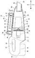
以下に本発明に係る充電式クリーナを実施するための実施の形態について、図面を参照しながら説明する。図1は、一部切欠いて断面視した充電式クリーナ10の一部切欠き断面図である。この充電式クリーナ10は、ハンディタイプ掃除機としての機能を有する充電式クリーナ本体20と、この充電式クリーナ本体20に対して配設される照明装置40とを備える。
図1に示すように、充電式クリーナ本体20は、前後方向に分割される前後2分割構造により構成される。充電式クリーナ本体20は、前後2分割構造の後側部分を構成するクリーナ基体21と、前後2分割構造の前側部分を構成するノズル構成部26とを備える。
クリーナ基体21は、概略、適宜の形状にて構成される基体ハウジング211と、この基体ハウジング211内に装置される送風機22とを備える。基体ハウジング211は、後に詳述するが、操作トリガ24が配設されたグリップ部23と、リチウムイオンバッテリ30を装着するためのバッテリ装着部25とが設けられている。なお、これらグリップ部23およびバッテリ装着部25は、基体ハウジング211のうち後側部分に設けられる。これに対して、基体ハウジング211のうち前側部分には、上記した送風機22が内蔵される。
送風機22は、回転駆動力を発生する駆動モータ221と、この駆動モータ221により発生した回転駆動力を受けて回転する送風ファン225とを備える。駆動モータ221は、広く利用されている電動モータであり、バッテリ装着部25に装着されるリチウムイオンバッテリ30から電力が供給されて回転駆動軸222を回転駆動させる。この回転駆動軸222は、送風ファン225の回転軸として機能するようになっており、送風ファン225は、回転駆動軸222の回転駆動を受けて回転駆動する。ここで、送風ファン225は、充電式クリーナ本体20内部にて前から後ろに向く方向で送風する軸流ファンとして構成される。このため、後にも説明するが、送風機22によりノズル28のノズル口281から吸入された空気は、ノズル構成部26内部を通過した後に送風ファン225を通過して、送風ファン225後側のクリーナ基体21から外部に排出される。
Embodiments for implementing a rechargeable cleaner according to the present invention will be described below with reference to the drawings. FIG. 1 is a partially cutaway cross-sectional view of a
As shown in FIG. 1, the
The
The
グリップ部23は、図示するような手握り形状を有して形成される。このグリップ部23は、ノズル28の延びる方向と同方向で手握りすることができる開口形状を有して形成されている。このグリップ部23を手握りした場合の人差し指部分には、操作トリガ24が配設されている。この操作トリガ24は、引き操作することにより操作オン状態となるような掃除機動作用の操作トリガである。このため、引き操作されていない自然状態時には、内部の戻りばねによって初期位置に位置することとなり、操作オフ状態となる。
バッテリ装着部25は、上記したグリップ部23の下側部分に設けられており、上記したようにリチウムイオンバッテリ30が装着される構造にて構成される。なお、このリチウムイオンバッテリ30は、図示していない充電器にて充電されるものであり、自己放電が小さい特性を有する。このため、このリチウムイオンバッテリ30は、長い間充電されていなくても充電されたままの状態が維持され易い特性を有するものとなっている。
なお、この充電式クリーナ本体20にあっては、バッテリ装着部25に対して装着状態となっているリチウムイオンバッテリ30の後面部分は、グリップ部23の後側部分と平面で面一となる縦置き面101が形成される。この縦置き面101は、充電式クリーナ本体20(クリーナ基体21、ノズル構成部26)が延びる方向と直交する方向に延在する平面にて形成されている。このため、この充電式クリーナ10は、この縦置き面101を接面させて縦置きすることができるものとなっている。
The
The
In the rechargeable
ノズル構成部26は、ノズル28を具備するノズルハウジング261と、このノズルハウジング261の内部に設けられるフィルタ部27とを備える。ノズルハウジング261は、ノズル28を具備し略カップ状に形成されるものである。このノズルハウジング261の前側部分には、ノズル28が設けられている。このノズル28は、ノズルハウジング261の内外を連通するノズル口281が形成されている。このノズルハウジング261の下側部分には、横置き用脚部29が、このノズルハウジング261と一体化されて設けられている。この横置き用脚部29の下面部分は、バッテリ装着部25に対して装着状態となっているリチウムイオンバッテリ30の下面部分と同一平面をなす横置き面102を形成する。このため、横置き用脚部29の下面部分となる横置き面102は、リチウムイオンバッテリ30の下面部分とともに接面させると、充電式クリーナ10を横置きすることができるものとなる。
フィルタ部27は、略カップ状に形成される。このフィルタ部27は、送風機22によってノズル28のノズル口281から吸入された空気を濾過するフィルタとして機能する。このため、フィルタ部27により、濾過された空気は上記したように送風ファン225を通過して送風ファン225後側のクリーナ基体21から外部に排出されるが、濾過された空気内のゴミはノズルハウジング261の内部に残ることとなる。
The nozzle
The
次に、上記した充電式クリーナ本体20に配設される照明装置40について説明する。図示するように、照明装置40は、上記したクリーナ基体21の基体ハウジング211と一体化されて配設されるものであり、ノズル構成部26の上部に載置されるように配置される。
照明装置40は、照明の機能目的が互いに相違する複数種類の照明機能を備えて構成される。すなわち、照明装置40は、白色発光ダイオード(以下、「LED(light emitting diode)」と称する)45を用いて照明する発光ダイオード照明機能と、蛍光灯55を用いて照明する蛍光灯照明機能との2種類の照明機能を備える。
照明装置40の発光ダイオード照明機能としては、LED照明部41にて構成される。このLED照明部41は、照明装置40の最前位置に配設されている。このLED照明部41は、ノズル28が延びる方向に沿って充電式クリーナ本体20前方を、フラッシュライト(懐中電灯)のようにスポット的に照らし出すことができる。
具体的にな構成としては、LED照明部41は、概略、ハウジング42と、集光ミラー43と、LED45と、透過カバー47とを備える。ハウジング42は、上記したクリーナ基体21の基体ハウジング211と一体化され、クリーナ基体21にて支持される。集光ミラー43は、ハウジング42にて支持され、適宜の凹面鏡構造を有する。この集光ミラー43は、充電式クリーナ本体20前方を照らし出すために、LED45が発光した光を集光する機能を有する。LED45は、適宜の白色発光ダイオードにより構成され、集光ミラー43の中心にて適宜の電気回路(LED用の専用電気回路)に電気的に接続されて支持されている。透過カバー47は、適宜の透過性樹脂にて形成されており、ハウジング42にて支持される。この透過カバー47は、集光ミラー43により集光したLED45の光を透過し、この透過した光は、上記したように充電式クリーナ本体20前方を、スポット的に照らし出すものとなっている。
照明装置40の蛍光灯照明機能としては、蛍光灯照明部51にて構成される。この蛍光灯照明部51は、照明装置40の中間位置に配設されている。この蛍光灯照明部51は、ノズル28が延びる方向に沿って蛍光灯55が配設されることにより、充電式クリーナ本体20の近傍周囲を広範囲で照らし出すことができる。
具体的にな構成としては、蛍光灯照明部51は、概略、透明樹脂ハウジング52と、蛍光灯55とを備える。透明樹脂ハウジング52は、上記したクリーナ基体21の基体ハウジング211と一体化され、クリーナ基体21にて支持される。この透明樹脂ハウジング52は、全方向に亘って光を透過することができるように、全周に亘って透明樹脂にて形成されてている。蛍光灯55は、広く利用されている蛍光灯と同様に構成されるものであり、全方向に亘って光を出すものである。この蛍光灯55は、透明樹脂ハウジング52内部に配設される適宜の電気回路(蛍光灯用の専用電気回路)に電気的に接続されて支持されている。このように蛍光灯照明部51の蛍光灯55は、充電式クリーナ本体20の近傍周囲を広範囲で照らし出すものとなっている。
Next, the illuminating
The illuminating
The light emitting diode illumination function of the
As a specific configuration, the
The fluorescent lamp illumination function of the
As a specific configuration, the fluorescent
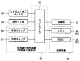
図1に示すように、上記した充電式クリーナ本体20の上部であり、上記した照明装置40の後部には、本発明に係る照明選択操作部に相当する照明選択操作装置60が、これら充電式クリーナ本体20および照明装置40の両方と一体化されるようにして配設されている。この照明選択操作装置60は、使用者の使用目的に応じて、上記したLED照明部41(発光ダイオード照明機能)および蛍光灯照明部51(蛍光灯照明機能)のいずれかを選択したり、これらのLED照明部41および蛍光灯照明部51をオンオフ操作したりするものである。なお、図2は、照明選択操作装置60と、照明装置40と、操作トリガ24との電気的制御ブロックを示すブロック図である。
この照明選択操作装置60は、図1に示すように、概略、コントローラ65と、単独スイッチ66と、切替スイッチ67とを備える。
照明選択操作装置60を構成するコントローラ65には、図2に示すように、この照明選択操作装置60を構成する単独スイッチ66および切替スイッチ67が電気的に接続されているほか、充電式クリーナ本体20の操作トリガ24、送風機22、リチウムイオンバッテリ30、照明装置40が電気的に接続されている。このコントローラ65は、単独スイッチ66、切替スイッチ67、操作トリガ24からの操作入力に応じて、送風機22、LED45、蛍光灯55のいずれかを選択してオンオフ動作の制御をしている。このため、このコントローラ65には、これら送風機22、LED45、蛍光灯55に対して電力供給するために、リチウムイオンバッテリ30が接続されている。
単独スイッチ66は、押下するたびにコントローラ65に入力信号を送る信号入力スイッチである。ここで、コントローラ65は、単独スイッチ66の押下のたびに入力信号を受信することとなる。この際、コントローラ65は、この入力信号を受信のたびに、次のように制御がシフトするものとなっている。すなわち、コントローラ65が単独スイッチ66から入力信号を1回受信すると、LED45を点灯させるようにオン動作させる。また、コントローラ65が単独スイッチ66から入力信号を2回受信すると、LED45を消灯させるようにオフ動作させる。また、コントローラ65が単独スイッチ66から入力信号を3回受信すると、蛍光灯55を点灯させるようにオン動作させる。また、コントローラ65が単独スイッチ66から入力信号を4回受信すると、蛍光灯55を消灯させるようにオフ動作させる。また、コントローラ65が単独スイッチ66から入力信号を5回受信すると、LED45および蛍光灯55の両方を点灯させるようにオン動作させる。また、コントローラ65が単独スイッチ66から入力信号を6回受信すると、LED45および蛍光灯55の両方を消灯させるようにオフ動作させる。
また、切替スイッチ67も、押下するたびにコントローラ65に入力信号を送る信号入力スイッチである。ここで、コントローラ65は、切替スイッチ67の押下のたびに入力信号を受信することとなる。この際、コントローラ65は、この入力信号を受信のたびに、次のように制御がシフトするものとなっている。すなわち、コントローラ65が切替スイッチ67から入力信号を1回受信すると、操作トリガ24の操作によって送風機22とLED45を連動操作できる制御状態とする。つまり、掃除機動作と照明機能動作とを、操作トリガ24の操作によって連動させるものとする。また、コントローラ65が切替スイッチ67から入力信号を2回受信すると、操作トリガ24の操作によってLED45だけを送風機22と非連動で単独操作できる制御状態とする。また、コントローラ65が切替スイッチ67から入力信号を3回受信すると、操作トリガ24の操作によっては送風機22だけをLED45と非連動で単独操作できる制御状態とする。なお、この状態は、通常のハンディタイプ掃除機としての動作制御状態である。
As shown in FIG. 1, an illumination
As shown in FIG. 1, the illumination
As shown in FIG. 2, a
The
The
上記したように構成された充電式クリーナ10によれば、次のような作用効果を奏することができる。
すなわち、上記した照明装置40は、照明の機能目的が互いに相違する2種類の照明機能を備える。つまり、照明装置40は、LED45を用いて照明する発光ダイオード照明機能と、蛍光灯55を用いて照明する蛍光灯照明機能との2種類の照明機能を備える。ここで、充電式クリーナ10によれば、この2種類の照明機能のいずれかを選択したり、この2種類の照明機能をオンオフ操作したりする照明選択操作装置60(照明選択操作部)が設けられているので、照明の使用目的に応じて照明機能を選択してオンオフ操作することができる。これによって、ハンディタイプ掃除機としての機能を有しつつ、照明の使用目的に応じて使用目的に合致した照明方法を選択できる。
また、上記した充電式クリーナ10によれば、照明選択操作装置60の選択操作には、掃除機動作と照明機能動作とを連動させる状態とする選択操作(切替スイッチ67の1回押下)が含まれているので、ハンディタイプ掃除機としてのオンオフ動作と連動して、LED45を用いて照明する発光ダイオード照明機能もオンオフ動作させることができる。これによって、充電式クリーナ10をハンディタイプ掃除機として使用する際に、掃除する場所を照らし出すことができて、掃除のし易いものとすることができる。
また、上記した充電式クリーナ10によれば、照明選択操作装置60の選択操作には、照明機能動作を非連動単独操作可能な状態に切り替える選択操作(切替スイッチ67の2回押下)が含まれているので、掃除機動作用の操作トリガ24のオンオフ操作に応じて、LED45を用いて照明する発光ダイオード照明機能を単独でオンオフ動作することとなる。これによって、一般のハンディタイプ掃除機のように充電式クリーナ10を片手で握りながら、LED照明部41(照明装置40)として使用することができる。つまり、そもそもハンディタイプ掃除機として設計される充電式クリーナ10は、片手で握り易いものとなっている上、操作トリガ24のオンオフ操作も握り手にて操作できるものとなっているので、この充電式クリーナ10をLED照明部41(照明装置40)として使用した場合、片手で握れて操作性の優れたものとなる。
また、上記した充電式クリーナ10によれば、照明装置40における2種類の照明機能には、LED45を用いて照明するLED照明部41(発光ダイオード照明機能)と、蛍光灯55を用いて照明する蛍光灯照明部51(蛍光灯照明機能)とを含んでいるので、LED照明部41を利用して常備灯のようにスポット的に照らし出すようにしたり、蛍光灯照明部51を利用して近傍周囲を広範囲で照らし出すようにしたりすることができる。
さらに、上記した充電式クリーナ10によれば、操作トリガ24のオンオフ操作に応じてオンオフ動作する照明機能としては、LED照明部41(発光ダイオード照明機能)が設定されているので、常備灯のようにスポット的に照らし出すような際に、片手で握った状態で操作性良く照らし出すことができる。特に、常備灯のようにスポット的に照らし出すには、上記したように片手で握っていると、LED照明部41による投射光の向きをコントロールし易くする。これによって、この充電式クリーナ10を常備灯として使用した場合、片手で握れて操作性の優れたものとなる。
According to the
That is, the above-described
Further, according to the
Further, according to the
Further, according to the above-described
Furthermore, according to the
なお、本発明に係る充電式クリーナにあっては、上記した実施の形態に限定されるものではなく、次のように適宜個所を変更して構成するようにしてもよい。
すなわち、上記した実施の形態における充電式クリーナ10にあっては、照明装置40が、LED45を用いて照明する発光ダイオード照明機能(LED照明部41)と、蛍光灯55を用いて照明する蛍光灯照明機能(蛍光灯照明部51)との2種類の照明機能を備えて構成されるものであった。しかしながら、本発明に係る複数種類の照明機能としては、照明の機能目的が互いに相違するものであれば、上記した2種類に加えて適宜の照明機能を有した照明部が新たに設けられるものであってよい。さらには、照明の機能目的が互いに相違するものとしては、照明光度や照明範囲が異なるものも含み、たとえば点滅や点灯色など適宜の制御点灯も含み、複数種類を上記したLED照明部41のみで制御点灯するものであってもよい。
また、上記した実施の形態における充電式クリーナ10にあっては、操作トリガ24の操作によって送風機22と連動操作できる制御状態となるのは、LED照明部41のLED45に設定されるものであった。しかしながら、本発明に係る掃除機動作用の操作トリガのオンオフ操作に連動してオンオフ動作する照明機能としては、蛍光灯55で設定されるものであってもよく、LED45および蛍光灯55の両者に設定されるものであってもよい。さらには、操作トリガ24のオンオフ操作に応じて、掃除機動作を連動させずに蛍光灯55単独でオンオフ動作させたり、掃除機動作を連動させずにLED45および蛍光灯55の両者をともにオンオフ動作させたりするものであってもよい。
Note that the rechargeable cleaner according to the present invention is not limited to the above-described embodiment, and may be configured with appropriate changes as follows.
That is, in the
Further, in the
10 充電式クリーナ
20 充電式クリーナ本体
21 クリーナ基体
211 基体ハウジング
22 送風機
221 駆動モータ
222 回転駆動軸
225 送風ファン
23 グリップ部
24 操作トリガ
25 バッテリ装着部
26 ノズル構成部
261 ノズルハウジング
27 フィルタ部
28 ノズル
281 ノズル口
29 横置き用脚部
30 リチウムイオンバッテリ
40 照明装置
41 LED照明部(発光ダイオード照明機能)
42 ハウジング
43 集光ミラー
47 透過カバー
51 蛍光灯照明部(蛍光灯照明機能)
52 透明樹脂ハウジング
55 蛍光灯
60 照明選択操作装置(照明選択操作部)
65 コントローラ
66 単独スイッチ
67 切替スイッチ
101 縦置き面
102 横置き面
DESCRIPTION OF
42
52
65
Claims (4)
前記照明装置は、照明の機能目的が互いに相違する複数種類の照明機能を備え、
充電式クリーナ本体もしくは前記照明装置のいずれかには、照明の使用目的に応じて該複数種類の照明機能のいずれかを選択したり該複数種類の照明機能をオンオフ操作したりする照明選択操作部が設けられていることを特徴とする充電式クリーナ。 It is a rechargeable cleaner in which a lighting device is arranged while having a function as a handy type vacuum cleaner,
The lighting device comprises a plurality of types of lighting functions whose functional purposes are different from each other,
Either a rechargeable cleaner body or the lighting device has an illumination selection operation unit that selects any one of the plurality of types of illumination functions or performs on / off operation of the plurality of types of illumination functions according to the purpose of use of illumination. A rechargeable cleaner characterized in that is provided.
前記照明選択操作部の選択操作には、前記ハンディタイプ掃除機としての動作をさせる掃除機動作用の操作トリガのオンオフ操作に応じて、前記照明装置における前記複数種類の照明機能のうち少なくとも1つの照明機能が該オンオフ操作に連動してオンオフ動作するように、掃除機動作と照明機能動作とを連動させる状態とする選択操作が含まれていることを特徴とする充電式クリーナ。 The rechargeable cleaner according to claim 1,
The selection operation of the illumination selection operation unit includes at least one illumination among the plurality of types of illumination functions in the illumination device according to an on / off operation of an operation trigger for a cleaner operation for causing the operation as the handy type cleaner. A rechargeable cleaner characterized by including a selection operation for bringing a vacuum cleaner operation and a lighting function operation into a linked state so that the function performs an on / off operation in conjunction with the on / off operation.
前記照明選択操作部の選択操作には、前記掃除機動作用の操作トリガのオンオフ操作に応じて、前記照明装置における前記複数種類の照明機能のうち少なくとも1つの照明機能が、前記ハンディタイプ掃除機としての動作とは非連動により単独でオンオフ動作するように、前記照明機能動作を非連動単独操作可能な状態に切り替える選択操作が含まれていることを特徴とする充電式クリーナ。 The rechargeable cleaner according to claim 2,
In the selection operation of the illumination selection operation unit, at least one illumination function among the plurality of types of illumination functions in the illumination device is used as the handy type vacuum cleaner according to an on / off operation of an operation trigger for the cleaner operation. A rechargeable cleaner comprising a selection operation for switching the illumination function operation to a state in which the operation of the illumination function can be performed independently without being interlocked so as to perform an on / off operation independently without being interlocked.
前記照明装置における前記複数種類の照明機能には、発光ダイオードを用いて照明する発光ダイオード照明機能と、蛍光灯を用いて照明する蛍光灯照明機能とを含み、
前記掃除機動作用の操作トリガのオンオフ操作に応じてオンオフ動作する前記複数種類の照明機能には、前記発光ダイオード照明機能が設定されていることを特徴とする充電式クリーナ。 In the rechargeable cleaner according to claim 2 or claim 3,
The plurality of types of illumination functions in the illumination device include a light-emitting diode illumination function that illuminates using a light-emitting diode, and a fluorescent lamp illumination function that illuminates using a fluorescent lamp,
The rechargeable cleaner, wherein the light-emitting diode illumination function is set in the plurality of types of illumination functions that are turned on and off in response to an on / off operation of an operation trigger for operating the cleaner.
Priority Applications (1)
| Application Number | Priority Date | Filing Date | Title |
|---|---|---|---|
| JP2010078181A JP2011206339A (en) | 2010-03-30 | 2010-03-30 | Charging type vacuum cleaner |
Applications Claiming Priority (1)
| Application Number | Priority Date | Filing Date | Title |
|---|---|---|---|
| JP2010078181A JP2011206339A (en) | 2010-03-30 | 2010-03-30 | Charging type vacuum cleaner |
Publications (2)
| Publication Number | Publication Date |
|---|---|
| JP2011206339A true JP2011206339A (en) | 2011-10-20 |
| JP2011206339A5 JP2011206339A5 (en) | 2012-12-20 |
Family
ID=44938113
Family Applications (1)
| Application Number | Title | Priority Date | Filing Date |
|---|---|---|---|
| JP2010078181A Pending JP2011206339A (en) | 2010-03-30 | 2010-03-30 | Charging type vacuum cleaner |
Country Status (1)
| Country | Link |
|---|---|
| JP (1) | JP2011206339A (en) |
Cited By (4)
| Publication number | Priority date | Publication date | Assignee | Title |
|---|---|---|---|---|
| WO2015043018A1 (en) * | 2013-09-30 | 2015-04-02 | 樊书印 | Miniature vacuum cleaner |
| CN106137048A (en) * | 2016-08-05 | 2016-11-23 | 江苏新光数控技术有限公司 | Automatic illuminating cleaning equipment |
| JP2019080853A (en) * | 2017-10-31 | 2019-05-30 | パナソニックIpマネジメント株式会社 | Collection system and collector |
| CN112263180A (en) * | 2020-11-17 | 2021-01-26 | 苏州市欧陆杰电器有限公司 | Pneumatic trigger control illuminating floor brush and using method thereof |
Citations (6)
| Publication number | Priority date | Publication date | Assignee | Title |
|---|---|---|---|---|
| JPS61164637U (en) * | 1985-04-01 | 1986-10-13 | ||
| JPS6395023A (en) * | 1986-10-09 | 1988-04-26 | 松下電器産業株式会社 | Vacuum cleaner with lighting device |
| JPS6371856U (en) * | 1986-10-29 | 1988-05-13 | ||
| JPH0922601A (en) * | 1995-07-07 | 1997-01-21 | Kihara Chuji | Portable signal indicator light |
| JPH11353901A (en) * | 1998-06-04 | 1999-12-24 | Aoki Denki Kogyo Kk | Emergency signal lamp with emergency escape device |
| JP2009279229A (en) * | 2008-05-23 | 2009-12-03 | Toshiba Corp | Vacuum cleaner |
-
2010
- 2010-03-30 JP JP2010078181A patent/JP2011206339A/en active Pending
Patent Citations (6)
| Publication number | Priority date | Publication date | Assignee | Title |
|---|---|---|---|---|
| JPS61164637U (en) * | 1985-04-01 | 1986-10-13 | ||
| JPS6395023A (en) * | 1986-10-09 | 1988-04-26 | 松下電器産業株式会社 | Vacuum cleaner with lighting device |
| JPS6371856U (en) * | 1986-10-29 | 1988-05-13 | ||
| JPH0922601A (en) * | 1995-07-07 | 1997-01-21 | Kihara Chuji | Portable signal indicator light |
| JPH11353901A (en) * | 1998-06-04 | 1999-12-24 | Aoki Denki Kogyo Kk | Emergency signal lamp with emergency escape device |
| JP2009279229A (en) * | 2008-05-23 | 2009-12-03 | Toshiba Corp | Vacuum cleaner |
Cited By (5)
| Publication number | Priority date | Publication date | Assignee | Title |
|---|---|---|---|---|
| WO2015043018A1 (en) * | 2013-09-30 | 2015-04-02 | 樊书印 | Miniature vacuum cleaner |
| CN106137048A (en) * | 2016-08-05 | 2016-11-23 | 江苏新光数控技术有限公司 | Automatic illuminating cleaning equipment |
| JP2019080853A (en) * | 2017-10-31 | 2019-05-30 | パナソニックIpマネジメント株式会社 | Collection system and collector |
| JP7122619B2 (en) | 2017-10-31 | 2022-08-22 | パナソニックIpマネジメント株式会社 | Collection system and collector |
| CN112263180A (en) * | 2020-11-17 | 2021-01-26 | 苏州市欧陆杰电器有限公司 | Pneumatic trigger control illuminating floor brush and using method thereof |
Similar Documents
| Publication | Publication Date | Title |
|---|---|---|
| CN105703029B (en) | Battery pack for a hand-held power tool | |
| US20080301903A1 (en) | Cleaner Handle and Cleaner Handle Housing Sections | |
| CN1816716A (en) | Multifunction flashlight and controller | |
| US20200166184A1 (en) | Task-area light | |
| JP2014036750A (en) | Cleaner | |
| EP2989374B1 (en) | Safety torch; set comprising a torch and a cartridge; holder for a safety tool | |
| JP2017531567A (en) | Grinding machine having at least one first housing part and lighting device module | |
| JP2011206339A (en) | Charging type vacuum cleaner | |
| JP2017127916A (en) | Electric power tool | |
| EP1664619B1 (en) | Vehicle charger/flashlight | |
| JP2007335282A (en) | Lighting device | |
| JP2009279229A (en) | Vacuum cleaner | |
| JP2011206339A5 (en) | ||
| WO2014012420A1 (en) | Multi-purpose battery lamp | |
| JP3164190U (en) | Switch panel lighting structure | |
| CN119159542A (en) | Handheld power tool including a light emitting unit and light emitting unit therefor | |
| CN212252154U (en) | LED flashlight and combined flashlight switch capable of stroboscopic light with multiple wavelengths | |
| GB2415494A (en) | Emergency lamp | |
| TWM258818U (en) | Saw blade hood with lighting device | |
| KR20120014719A (en) | Car interior light | |
| KR102515774B1 (en) | Portable multy vacuum cleaner | |
| KR200178902Y1 (en) | Handy vacuum cleaner | |
| JP3061915U (en) | Voltage detector | |
| JP2007141598A (en) | Emergency flashlight and emergency lighting device | |
| JP3113590U (en) | Portable power charger |
Legal Events
| Date | Code | Title | Description |
|---|---|---|---|
| A521 | Written amendment |
Free format text: JAPANESE INTERMEDIATE CODE: A523 Effective date: 20121105 |
|
| A621 | Written request for application examination |
Free format text: JAPANESE INTERMEDIATE CODE: A621 Effective date: 20121105 |
|
| A977 | Report on retrieval |
Free format text: JAPANESE INTERMEDIATE CODE: A971007 Effective date: 20130912 |
|
| A131 | Notification of reasons for refusal |
Free format text: JAPANESE INTERMEDIATE CODE: A131 Effective date: 20131008 |
|
| A02 | Decision of refusal |
Free format text: JAPANESE INTERMEDIATE CODE: A02 Effective date: 20140225 |