JP2017127916A - Electric power tool - Google Patents

Electric power tool Download PDF

Info

Publication number
JP2017127916A
JP2017127916A JP2016007942A JP2016007942A JP2017127916A JP 2017127916 A JP2017127916 A JP 2017127916A JP 2016007942 A JP2016007942 A JP 2016007942A JP 2016007942 A JP2016007942 A JP 2016007942A JP 2017127916 A JP2017127916 A JP 2017127916A
Authority
JP
Japan
Prior art keywords
tool
operation state
screen
electric
main body
Prior art date
Legal status (The legal status is an assumption and is not a legal conclusion. Google has not performed a legal analysis and makes no representation as to the accuracy of the status listed.)
Pending
Application number
JP2016007942A
Other languages
Japanese (ja)
Other versions
JP2017127916A5 (en
Inventor
友幸 近藤
Tomoyuki Kondo
友幸 近藤
功児 塚本
Koji Tsukamoto
功児 塚本
治樹 手島
Haruki Tejima
治樹 手島
Current Assignee (The listed assignees may be inaccurate. Google has not performed a legal analysis and makes no representation or warranty as to the accuracy of the list.)
Makita Corp
Original Assignee
Makita Corp
Priority date (The priority date is an assumption and is not a legal conclusion. Google has not performed a legal analysis and makes no representation as to the accuracy of the date listed.)
Filing date
Publication date
Application filed by Makita Corp filed Critical Makita Corp
Priority to JP2016007942A priority Critical patent/JP2017127916A/en
Publication of JP2017127916A publication Critical patent/JP2017127916A/en
Publication of JP2017127916A5 publication Critical patent/JP2017127916A5/ja
Pending legal-status Critical Current

Links

Images

Classifications

    • BPERFORMING OPERATIONS; TRANSPORTING
    • B25HAND TOOLS; PORTABLE POWER-DRIVEN TOOLS; MANIPULATORS
    • B25FCOMBINATION OR MULTI-PURPOSE TOOLS NOT OTHERWISE PROVIDED FOR; DETAILS OR COMPONENTS OF PORTABLE POWER-DRIVEN TOOLS NOT PARTICULARLY RELATED TO THE OPERATIONS PERFORMED AND NOT OTHERWISE PROVIDED FOR
    • B25F5/00Details or components of portable power-driven tools not particularly related to the operations performed and not otherwise provided for
    • B25F5/02Construction of casings, bodies or handles
    • B25F5/021Construction of casings, bodies or handles with guiding devices

Abstract

PROBLEM TO BE SOLVED: To enable more information to be notified without limiting a display space, by solving a problem in that an electric power tool such as an electric screw fastening machine is provided with a display panel for changing an operation mode for a tool body part or for checking a set operation mode, but the display panel is disposed in a limited space, resulting in limit on an amount of information that can be displayed.SOLUTION: A multi-color LED is used as a light source for a light emission part 42, 43, which causes an operating state to be notified of, such as output from a tool body part 10 and a remaining quantity in a battery pack 19. By changing color development in the light emission part 42, 43, a plurality of operating states can be notified using one light emission part 42, 43 alone. In addition, a state of operation setting is notified with sound. In addition, using a projector apparatus provided on the interior, an image screen for displaying a state of operation setting is enlarged and projected on a screen as on a wall surface, thereby informing the state of operation setting.SELECTED DRAWING: Figure 1

Description

この発明は、例えばインパクトドライバと称される電動ねじ締め機であって、電動モータを駆動源として内装した電動工具に関する。   The present invention relates to an electric screw tightener called an impact driver, for example, and relates to an electric tool equipped with an electric motor as a drive source.

例えばねじ締め機等の電動工具では、内装した電動モータの回転数や出力等(動作状態)を使用者が視覚的に確認できるようにするための動作表示部が設けられている。また、充電可能なバッテリパックを電源として用いる充電式の電動工具では、バッテリパックの残容量を視覚的に表示する残容量表示部が設けられている。下記の特許文献1には、使用者が把持するグリップ部の下部に電動モータの動作を制御するコントローラと、このコントローラにより動作制御される電動モータの動作状態等を視覚的に表示する表示部を設けた回転打撃工具に関する技術が開示されている。   For example, in an electric tool such as a screw tightener, an operation display unit is provided for allowing a user to visually check the rotation speed, output, etc. (operation state) of an internal electric motor. Further, in a rechargeable electric tool that uses a rechargeable battery pack as a power source, a remaining capacity display unit that visually displays the remaining capacity of the battery pack is provided. In the following Patent Document 1, a controller that controls the operation of the electric motor at the lower part of the grip unit gripped by the user, and a display unit that visually displays the operation state of the electric motor controlled by the controller. A technique related to the provided rotary impact tool is disclosed.

特開2012−139747号公報JP 2012-139747 A

電動工具の動作状態等を視覚的に報知する表示部(表示パネル)については、次のような問題があった。近年特に回転打撃工具等のねじ締め機については、作業内容や締め付けるねじの種類等に合わせて動作モードを切り換えることができるようにしたり、出力回転数を任意に設定できるようにする等の多機能化に伴って、その表示部についても大型化する傾向にある。また、表示部に、モード切替スイッチや照明具を点灯、消灯させる照明スイッチを配置する場合には、一層大型化しやすくなる。   The display unit (display panel) that visually notifies the operating state of the power tool has the following problems. In recent years, especially for screw tightening machines such as rotary impact tools, it is possible to switch the operation mode according to the work content, the type of screw to be tightened, etc., and to make it possible to arbitrarily set the output rotation speed etc. With the increase in size, the display portion tends to increase in size. In addition, when the display unit is provided with a mode switch or a lighting switch for turning on / off the lighting device, the size can be further increased.

しかしながら、表示部を配置できる部位は限られており、表示部の大型化にも限界がある。逆に、多機能表示の表示部を小型化すれば、各表示及びその文字表記の視認性が損なわれ、また各種スイッチの操作性が損なわれてしまう。このため、従来より当該表示部について大型化を招くことなく、視認性を確保しつつより多くの情報を報知するための工夫がなされている。   However, the part where the display unit can be arranged is limited, and there is a limit to increasing the size of the display unit. On the other hand, if the display portion of the multi-function display is downsized, the visibility of each display and its character notation is impaired, and the operability of various switches is impaired. For this reason, the device for alert | reporting more information conventionally is ensured, ensuring visibility, without causing the enlargement about the said display part.

本発明は係る従来の問題に鑑みてなされたもので、主として電動モータ等の動作状態を表示する表示部について、その視認性や操作性を損なうことなく、より多くの表示を可能とし、また各種の操作スイッチを配置できるようにすることを目的とする。   The present invention has been made in view of the related art problems. For display units that mainly display the operating state of an electric motor or the like, it is possible to display more without impairing the visibility and operability. It is an object to be able to arrange the operation switches.

上記の課題は、以下の各発明により解決される。第1の発明は、電動モータを駆動源として動作する工具本体部と、工具本体部の動作状態をLEDの発光色を変化させて報知する動作状態報知部を備えた電動工具である。   Said subject is solved by each following invention. 1st invention is an electric tool provided with the operation state alerting | reporting part which changes the luminescent color of LED and alert | reports the operation state of a tool main-body part which operate | moves using an electric motor as a drive source.

第1の発明によれば、一つのLEDを光源とする発光部により、工具本体部の動作状態に関して複数の状態を報知することができる。このため、各動作状態に対応して複数の発光部を配置する従来構成に比して動作状態報知部の表示面積をコンパクトに構成できるとともに、より多くの動作状態を報知できるようになる。発光部の発光色は、工具本体部の動作状態であってその出力が大きくなるに従って例えば青色→黄色→赤色に変化させることができる。   According to the first aspect of the present invention, a plurality of states can be notified regarding the operating state of the tool body by the light emitting unit using one LED as a light source. For this reason, the display area of the operation state notification unit can be made compact compared to the conventional configuration in which a plurality of light emitting units are arranged corresponding to each operation state, and more operation states can be notified. The light emission color of the light emitting unit can be changed from blue to yellow to red, for example, as the output of the tool main body is increased and the output thereof increases.

第2の発明は、第1の発明において、動作状態報知部は、電動モータの出力(回転速度)を切り替える切替スイッチと、前記電動モータの出力をLEDの発光色を変化させて報知する発光部を備えた電動工具である。   According to a second aspect, in the first aspect, the operation state notifying unit is a changeover switch that switches an output (rotation speed) of the electric motor, and a light emitting unit that notifies the output of the electric motor by changing the emission color of the LED. It is an electric tool provided with.

第2の発明によれば、切替スイッチの操作により工具本体部の動作状態を切り替えると、これに合わせて発光部の発光色が変化して、当該工具本体部の動作状態が切り替わったことが報知される。発光部の発光色が変化することにより、工具本体部の動作状態について複数の状態が報知される。   According to the second invention, when the operating state of the tool main body is switched by operating the changeover switch, the light emission color of the light emitting portion changes accordingly, and the operating status of the tool main body is switched. Is done. By changing the light emission color of the light emitting unit, a plurality of states are notified about the operation state of the tool body.

第3の発明は、電動モータを駆動源として動作する工具本体部と、工具本体部の動作状態を音で報知する動作状態報知部を備えた電動工具である。   3rd invention is an electric tool provided with the tool main-body part which operate | moves using an electric motor as a drive source, and the operation state alerting | reporting part which alert | reports the operation state of a tool main-body part with a sound.

第3の発明によれば、工具本体部の出力等に関する動作状態が音声若しくは音により報知される(聴覚的報知手段)。このため、使用者は耳で聞いて工具本体部の動作状態を確認することができるので、目で見て確認する表示パネル等の視覚的報知手段を必要とせず、この点で電動工具のコンパクト化を図ることができる。また、使用者は耳で音を聞いて工具本体部の動作状態を確認することができるので、作業部位を目視したまま工具本体部の動作状態を確認することができ、この点で作業性を高めることができる。   According to the third aspect of the invention, the operation state relating to the output of the tool body is notified by voice or sound (auditory notification means). For this reason, since the user can confirm the operating state of the tool body by listening with his / her ears, there is no need for visual notification means such as a display panel for visual confirmation. Can be achieved. In addition, since the user can confirm the operating state of the tool body by listening to the sound with his / her ears, the operating state of the tool body can be confirmed while observing the work site. Can be increased.

第4の発明は、第3の発明において、使用者が把持するグリップ部を備えており、該グリップ部に前記音を発するスピーカを内装し、前記工具本体部の後面に設けた切り替えスイッチの操作により前記工具本体部の動作状態を切り替えると、当該動作状態が前記スピーカから発せられる音により報知される構成とした電動工具である。   According to a fourth aspect of the present invention, in the third aspect of the present invention, a grip portion that is held by a user is provided, a speaker that emits the sound is provided in the grip portion, and an operation of a changeover switch provided on the rear surface of the tool body portion When the operation state of the tool main body is switched by this, the operation state is notified by sound emitted from the speaker.

第4の発明によれば、比較的空きスペースが多く存在するグリップ部の内部を有効に活用してスピーカを配置することができ、この点で当該電動工具のコンパクト化を図ることができる。また、工具本体部の後面に切り替えスイッチが配置されていることにより、使用者はグリップ部をわざわざ持ち替える等の手間をかけることなく、工具本体部の動作状態を切り替えることができ、この点で当該電動工具の操作性を高めることができる。   According to the fourth aspect of the present invention, the speaker can be arranged by effectively utilizing the inside of the grip portion having a relatively large space, and in this respect, the electric tool can be made compact. In addition, since the change-over switch is arranged on the rear surface of the tool main body, the user can switch the operation state of the tool main body without taking the trouble of changing the grip part. The operability of the power tool can be improved.

第5の発明は、電動モータを駆動源として動作する工具本体部と、工具本体部の動作状態に関する情報をスクリーン上に拡大投影して報知する動作状態報知部を備えた電動工具である。   A fifth invention is an electric tool including a tool main body that operates using an electric motor as a drive source, and an operation state notifying unit that reports information on an operation state of the tool main body on an enlarged screen.

第5の発明によれば、当該電動工具の限られたスペースに表示部を設ける必要がないので、そのコンパクト化を図ることができるとともに、より多くの情報をより見え易い状態で報知することができる。また、スクリーンには、作業現場の壁面、床面、天井面のほか、車両のボディ、ウインドガラス等を利用することができ、その場で即座に工具本体部の動作状態を切り替えてその確認をすることができ、この点で当該電動工具の操作性及び使い勝手を高めるとともに作業性を高めることができる。第5の発明に係る動作状態報知部により報知される情報としては、電動工具の回転出力、バッテリパックの残容量、当該電動工具の取り扱い説明書、当該電動工具若しくはバッテリパックの寿命に関する情報、作業用図面等をスクリーンに拡大投影して報知することができる。   According to the fifth invention, since it is not necessary to provide a display unit in a limited space of the electric power tool, it is possible to reduce the size of the power tool and to notify more information in a state where it can be easily seen. it can. In addition to the wall surface, floor surface, and ceiling surface of the work site, the body of the vehicle, window glass, etc. can be used for the screen, and the operation status of the tool body can be switched immediately on the spot for confirmation. In this respect, the operability and usability of the power tool can be improved and workability can be improved. Information notified by the operation state notifying unit according to the fifth invention includes the rotation output of the electric tool, the remaining capacity of the battery pack, the instruction manual of the electric tool, information on the life of the electric tool or the battery pack, work A drawing or the like can be enlarged and projected on a screen for notification.

第1実施形態に係る電動工具の全体斜視図である。本図は、電動工具の一例として充電式のねじ締め機を例示している。It is a whole perspective view of the electric tool concerning a 1st embodiment. This figure has illustrated the rechargeable screwing machine as an example of an electric tool. 第1実施形態に係る電動工具の縦断面図である。It is a longitudinal cross-sectional view of the electric tool which concerns on 1st Embodiment. 第1実施形態に係る電動工具を図1中矢印(III)方向から見た前面図である。本図では、動作状態報知部が縦断面で示されている。It is the front view which looked at the electric tool which concerns on 1st Embodiment from the arrow (III) direction in FIG. In this figure, the operation state notification unit is shown in a vertical section. 図2の(IV)-(IV)線断面矢視図であって、電源部の平面図である。It is the (IV)-(IV) sectional view taken on the line of FIG. 2, Comprising: It is a top view of a power supply part. 図2の(V)部拡大図であって、モード切替スイッチの縦断面図である。FIG. 3 is an enlarged view of a part (V) in FIG. 2, and is a longitudinal sectional view of a mode changeover switch. 第2実施形態に係る電動工具の縦断面図である。It is a longitudinal cross-sectional view of the electric tool which concerns on 2nd Embodiment. 第2実施形態に係る動作状態報知部による報知内容を示す図である。本図は、モード切替スイッチの操作による打撃力の切り替え状態を報知する場合を示している。It is a figure which shows the alerting | reporting content by the operation state alerting | reporting part which concerns on 2nd Embodiment. This figure has shown the case where the change state of the striking force by operation of a mode change switch is alert | reported. 第2実施形態に係る動作状態報知部による報知内容を示す図である。本図は、バッテリパックの残容量を報知する場合を示している。It is a figure which shows the alerting | reporting content by the operation state alerting | reporting part which concerns on 2nd Embodiment. This figure has shown the case where the remaining capacity of a battery pack is alert | reported. 第3実施形態に係る電動工具の縦断面図である。It is a longitudinal cross-sectional view of the electric tool which concerns on 3rd Embodiment. 第3実施形態に係る電動工具が備える操作パネルを示す図である。It is a figure which shows the operation panel with which the electric tool which concerns on 3rd Embodiment is provided. 第3実施形態に係る電動工具が備える別形態の操作パネルを示す図である。It is a figure which shows the operation panel of another form with which the electric tool which concerns on 3rd Embodiment is provided. スクリーン上に投影された画面を示す図である。本図は、初期画面を示している。It is a figure which shows the screen projected on the screen. This figure shows the initial screen. スクリーン上に投影された画面を示す図である。本図は、打撃力の強弱を示す画面を示している。It is a figure which shows the screen projected on the screen. This figure has shown the screen which shows the strength of striking power. スクリーン上に投影された画面を示す図である。本図は、テクスモードにおける回転スピードと打撃検知感度を報知する画面を示している。It is a figure which shows the screen projected on the screen. This figure has shown the screen which alert | reports the rotational speed and impact detection sensitivity in text mode. スクリーン上に投影された画面を示す図である。本図は、その他の設定を行うための画面を示している。It is a figure which shows the screen projected on the screen. This figure shows a screen for performing other settings. スクリーン上に投影された画面を示す図である。本図は、現在の設定状態を報知する画面を示している。It is a figure which shows the screen projected on the screen. This figure has shown the screen which alert | reports the present setting state. スクリーン上に投影された画面を示す図である。本図は、初期設定を行うための画面を示している。It is a figure which shows the screen projected on the screen. This figure shows a screen for initial setting.

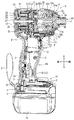
次に、本発明の実施形態を図1〜図17に基づいて説明する。図1〜図3に示すように、本実施形態では電動工具1の一例として、いわゆるインパクト式のねじ締め機(インパクトドライバ)を例示する。以下の説明において、電動工具1の前後方向については、出力側(先端工具側)を前側とし、使用者から見て手前側を後ろ側とする。また、左右方向についてはグリップ部15を把持した使用者を基準にして用いる。   Next, an embodiment of the present invention will be described with reference to FIGS. As shown in FIGS. 1 to 3, in this embodiment, as an example of the electric tool 1, a so-called impact type screw tightening machine (impact driver) is illustrated. In the following description, with respect to the front-rear direction of the electric power tool 1, the output side (tip tool side) is the front side, and the front side as viewed from the user is the rear side. The left and right directions are used based on the user who holds the grip portion 15.

電動工具1は、工具本体部10と、工具本体部10の下面から下方へ突き出す状態に設けられたグリップ部15を備えている。工具本体部10は、概ね円筒形の本体ケース11を備えている。本体ケース11の後面側は、後部ケース12により閉塞されている。   The electric tool 1 includes a tool main body 10 and a grip 15 provided in a state of protruding downward from the lower surface of the tool main body 10. The tool body 10 includes a substantially cylindrical body case 11. The rear surface side of the main body case 11 is closed by the rear case 12.

グリップ部15は、使用者が当該電動工具1を使用する際に把持する部分であり、その前面上部には使用者が指先で引き操作するトリガ16が設けられている。このトリガ16を引き操作するとグリップ部15内に収容したメインスイッチ18がオンする。メインスイッチ18がオンすると、工具本体部10に内装した駆動源としての電動モータ20が起動する。   The grip portion 15 is a portion that is gripped when the user uses the electric power tool 1, and a trigger 16 that is pulled by the user with a fingertip is provided at the upper front portion of the grip portion 15. When the trigger 16 is pulled, the main switch 18 accommodated in the grip portion 15 is turned on. When the main switch 18 is turned on, the electric motor 20 as a drive source built in the tool body 10 is activated.

本体ケース11とグリップ部15は、左右の半割りケースを相互に結合して一体化した半割り構造を備えている。本体ケース11とグリップ部15の半割り構造は、合計8本のねじ2で相互に結合されている。図では見えていないが、後部ケース12は4本のねじで本体ケース11の後部に結合されている。   The main body case 11 and the grip portion 15 have a halved structure in which the left and right halved cases are combined and integrated. The half structure of the main body case 11 and the grip portion 15 is coupled to each other by a total of eight screws 2. Although not visible in the figure, the rear case 12 is coupled to the rear portion of the main body case 11 with four screws.

グリップ部15の下部には、当該電動工具1の電源としてのバッテリパック19を装着するための電源部17が設けられている。この電源部17は、主として前方(図1,2において右側)へ張り出す状態(拡径部)に設けられている。この電源部17の下面側にバッテリパック19が装着される。電源部17の上面には、当該電動工具1の動作状態を視覚的に報知するための動作状態報知部40が設けられている。本実施形態はこの動作状態報知部40について特徴を有している。動作状態報知部40の特徴については後述する。   A power source unit 17 for mounting a battery pack 19 as a power source of the electric tool 1 is provided at the lower part of the grip unit 15. This power supply part 17 is provided in the state (diameter enlarged part) mainly projected ahead (right side in FIGS. 1, 2). A battery pack 19 is attached to the lower surface side of the power supply unit 17. On the upper surface of the power supply unit 17, an operation state notifying unit 40 for visually informing the operation state of the electric power tool 1 is provided. The present embodiment is characterized by this operation state notification unit 40. The features of the operating state notification unit 40 will be described later.

図2に示すように本体ケース11内には、その後側から順番に電動モータ20、遊星歯車機構30、駆動軸31、回転打撃機構32、及びアンビル33が同軸に収納されている。電動モータ20の回転出力が遊星歯車機構30及び回転打撃機構32を経てアンビル33に伝達される。   As shown in FIG. 2, the electric motor 20, the planetary gear mechanism 30, the drive shaft 31, the rotary impact mechanism 32, and the anvil 33 are accommodated in the main body case 11 in order from the rear side. The rotational output of the electric motor 20 is transmitted to the anvil 33 through the planetary gear mechanism 30 and the rotary impact mechanism 32.

回転打撃機構32は、駆動軸31の回転をアンビル33に対する回転打撃動作に変換する機能を有するもので、駆動軸31に対して同軸で回転可能かつ軸方向移動可能に支持されたハンマー32aと、このハンマー32aを先端側に付勢する圧縮ばね32bと、ハンマー32aの軸方向移動と回転動作を規制する2つの鋼球32cを備えている。2つの鋼球32cは、それぞれ駆動軸31に設けた断面半円形の溝部31aに嵌り込んでいる。溝部31aは、出力軸線Jに対して傾斜する方向に沿って設けられている。このため、ハンマー32aは、駆動軸31に対して出力軸線J回りに回転しつつ、出力軸線J方向に進退する。ハンマー32aは、圧縮ばね32bに抗して後退し、圧縮ばね32bの付勢力により前進する。   The rotary hitting mechanism 32 has a function of converting the rotation of the drive shaft 31 into a rotary hitting operation with respect to the anvil 33. The hammer 32a is coaxially rotated with respect to the drive shaft 31 and supported so as to be axially movable. A compression spring 32b that biases the hammer 32a toward the tip side and two steel balls 32c that restrict axial movement and rotation of the hammer 32a are provided. The two steel balls 32c are fitted in groove portions 31a each having a semicircular cross section provided on the drive shaft 31. The groove 31 a is provided along a direction inclined with respect to the output axis J. For this reason, the hammer 32 a advances and retreats in the direction of the output axis J while rotating around the output axis J with respect to the drive shaft 31. The hammer 32a moves backward against the compression spring 32b and moves forward by the urging force of the compression spring 32b.

アンビル33は、駆動軸31の先端に同軸で相対回転可能に支持されている。このアンビル33の軸部(出力軸36)は、ころ軸受34を介して本体ケース11の先端部に対して軸回りに回転自在に支持されている。   The anvil 33 is coaxially supported at the tip of the drive shaft 31 so as to be relatively rotatable. A shaft portion (output shaft 36) of the anvil 33 is supported via a roller bearing 34 so as to be rotatable about the axis with respect to the tip portion of the main body case 11.

ねじ締め開始後、ねじ締め負荷が小さい段階では、アンビル33は回転打撃機構32を介して駆動軸31と一体でねじ締め方向へ回転する。ねじ締めが進行してねじ締め負荷が駆動軸31に伝達される回転出力に勝ると、ハンマー32aが圧縮ばね32bに抗して駆動軸31に対して相対回転しつつ軸方向に後退する。ハンマー32aが圧縮ばね32bに抗して後退するとアンビル33に対する係合状態が外れる。このため、ハンマー32aが圧縮ばね32bの付勢力によって前進しつつ回転してアンビル33をねじ締め方向に打撃する。本体ケース11の前部から突き出された出力軸36の先端部には、ドライバビットやソケットビット等の先端工具(図示省略)を装着するための工具保持部35が設けられている。   After the start of screw tightening, at a stage where the screw tightening load is small, the anvil 33 rotates in the screw tightening direction integrally with the drive shaft 31 via the rotary impact mechanism 32. When the screw tightening advances and the screw tightening load is greater than the rotational output transmitted to the drive shaft 31, the hammer 32a moves backward in the axial direction while rotating relative to the drive shaft 31 against the compression spring 32b. When the hammer 32a moves backward against the compression spring 32b, the engagement state with the anvil 33 is released. For this reason, the hammer 32a rotates while moving forward by the urging force of the compression spring 32b, and strikes the anvil 33 in the screw tightening direction. A tool holding portion 35 for mounting a tip tool (not shown) such as a driver bit or a socket bit is provided at the tip portion of the output shaft 36 protruding from the front portion of the main body case 11.

電動モータ20はDCブラシレスモータで、本体ケース11の内側に固定された固定子21と、固定子21の内周側にモータ軸24を介して回転自在に支持された回転子22を備えている。モータ軸24は、前後二つの軸受25,26を介してその軸線(出力軸線J)回りに回転自在に支持されている。軸受25,26にはそれぞれ玉軸受(ボールベアリング)が用いられている。前側の軸受25は、本体ケース11内を前後に区画する中間区画壁27に保持されている。この中間区画壁27によって当該本体ケース11内が電動モータ20側(後側)と回転打撃機構32側(前側)に区画されている。   The electric motor 20 is a DC brushless motor, and includes a stator 21 fixed inside the main body case 11 and a rotor 22 rotatably supported on the inner peripheral side of the stator 21 via a motor shaft 24. . The motor shaft 24 is rotatably supported around its axis (output axis J) via two front and rear bearings 25 and 26. Ball bearings (ball bearings) are used for the bearings 25 and 26, respectively. The front bearing 25 is held by an intermediate partition wall 27 that partitions the main body case 11 forward and backward. The inside of the main body case 11 is partitioned by the intermediate partition wall 27 into the electric motor 20 side (rear side) and the rotary impact mechanism 32 side (front side).

固定子21の前側には、回転子22の回転位置を検出するための磁気センサを有するセンサ基板23が配置されている。センサ基板23は概ね円板形を有しており、固定子21の前端面に対向する状態で配置されている。固定子21と後ろ側の軸受26との間においてモータ軸24上に冷却ファン28が取り付けられている。冷却ファン28にはいわゆる遠心ファンが用いられている。後ろ側の軸受26は、後部ケース12の内面に設けた軸受保持部12aに保持されている。なお、本実施形態では、冷却ファン28が回転子22の後ろ側に配置され、センサ基板23が固定子の前面側に配置された構成を例示しているが、冷却ファンとセンサ基板が前後逆に配置された電動モータについても同様に適用することができる。   A sensor substrate 23 having a magnetic sensor for detecting the rotational position of the rotor 22 is disposed on the front side of the stator 21. The sensor substrate 23 has a substantially disk shape and is disposed in a state of facing the front end surface of the stator 21. A cooling fan 28 is mounted on the motor shaft 24 between the stator 21 and the rear bearing 26. A so-called centrifugal fan is used as the cooling fan 28. The rear bearing 26 is held by a bearing holding portion 12 a provided on the inner surface of the rear case 12. In this embodiment, the cooling fan 28 is disposed on the rear side of the rotor 22 and the sensor substrate 23 is disposed on the front side of the stator. However, the cooling fan and the sensor substrate are reversed in the front-rear direction. The same can be applied to the electric motor arranged in the above.

工具本体部10の前部には、照明具5が装備されている。照明具5には、LED(発光ダイオード)が用いられている。照明具5は透明カバー5aで覆われている。この照明具5によって加工部位が明るく照らされて暗い場所での作業の便宜が図られる。本実施形態では、照明具5は、トリガ16を軽く引き操作すると点灯し、引き操作を解除すると消灯する。なお、照明具5の点灯スイッチは、後述する動作状態報知部40に配置することもできる。   A lighting tool 5 is provided at the front part of the tool body 10. An LED (light emitting diode) is used for the illumination tool 5. The illumination tool 5 is covered with a transparent cover 5a. The working part is brightly illuminated by the illuminator 5 to facilitate work in a dark place. In this embodiment, the illuminator 5 is turned on when the trigger 16 is pulled lightly, and turned off when the pulling operation is released. In addition, the lighting switch of the lighting fixture 5 can also be arrange | positioned in the operation state alerting | reporting part 40 mentioned later.

工具本体部10の下面側であってグリップ部15の基部には、出力軸36の回転方向を切り換えるための切り替えスイッチ6が配置されている。この切り替えスイッチ6を左右に切り換えることにより、出力軸36をねじ締め方向またはねじ緩め方向に回転させることができる。   A changeover switch 6 for switching the rotation direction of the output shaft 36 is disposed on the lower surface side of the tool main body 10 and at the base of the grip portion 15. By switching the changeover switch 6 to the left or right, the output shaft 36 can be rotated in the screw tightening direction or the screw loosening direction.

電源部17の後部には、ループ形のハンドストラップ3が取り付けられている。このハンドストラップ3は、電源部17においてグリップ部15の左右半割り構造を結合する2本のねじ2のうち後ろ側のねじ2によって結合されている。このハンドストラップ3に手首を通しておくことにより、当該電動工具1を誤って落下させてしまうことが防止される。また、図3に示すように電源部17の左側部には、大型のフック4が取り付けられている。U字形を有するフック4は上方に開いた向きで取り付けられている。当該電動工具1を上下逆さまにした姿勢でフック4を使用者の腰ベルトに引き掛けておくことにより当該電動工具1をぶら下げた状態で携行することができる。   A loop-shaped hand strap 3 is attached to the rear portion of the power supply unit 17. The hand strap 3 is coupled by a screw 2 on the rear side of the two screws 2 that couple the left and right halved structures of the grip unit 15 in the power supply unit 17. By passing the wrist through the hand strap 3, it is possible to prevent the electric tool 1 from being accidentally dropped. As shown in FIG. 3, a large hook 4 is attached to the left side of the power supply unit 17. The hook 4 having a U-shape is attached in an upwardly opening direction. The electric tool 1 can be carried in a suspended state by hooking the hook 4 on the waist belt of the user in a posture in which the electric tool 1 is turned upside down.

図2及び図3に示すように、電源部17には、平板形状のコントローラ9が収容されている。このコントローラ9は、モータ制御回路や電源回路等を含む制御基板7を矩形底浅のケース8に収容した構成を備えている。制御基板7の上面にはコンデンサ7aが搭載されている。制御基板7は樹脂モールドされて絶縁された状態でケース8に収容されている。図では見えていないがコントローラ9の下面側には、バッテリパック19を電気的に接続するための正負の接続端子が装備されている。正負の接続端子に結線された2本の電源線は、上方へ引き出されてグリップ部15内を配線され、センサ基板23に結線されている。センサ基板23の下部は、固定子21よりも外周側へ張り出しており、この張り出し部分の前面に2本の電源線が結線されている。   As shown in FIGS. 2 and 3, the power supply unit 17 accommodates a flat plate-shaped controller 9. The controller 9 has a configuration in which a control board 7 including a motor control circuit, a power supply circuit, and the like is accommodated in a case 8 having a rectangular bottom. A capacitor 7 a is mounted on the upper surface of the control board 7. The control board 7 is accommodated in the case 8 in a resin-molded and insulated state. Although not visible in the drawing, positive and negative connection terminals for electrically connecting the battery pack 19 are provided on the lower surface side of the controller 9. The two power supply wires connected to the positive and negative connection terminals are drawn upward, wired in the grip portion 15, and connected to the sensor substrate 23. The lower part of the sensor substrate 23 projects outward from the stator 21, and two power lines are connected to the front surface of the projecting part.

電源部17の下面に対してバッテリパック19を前側から後ろ側へスライドさせることにより当該バッテリパック19を電源部17に取り付けることができる。バッテリパック19は、例えば出力電圧14.4V仕様のリチウムイオンバッテリで、取り外して別途用意した充電器で充電することにより繰り返し使用することができる。   The battery pack 19 can be attached to the power supply unit 17 by sliding the battery pack 19 from the front side to the rear side with respect to the lower surface of the power supply unit 17. The battery pack 19 is, for example, a lithium ion battery having an output voltage specification of 14.4 V, and can be repeatedly used by being removed and charged with a separately prepared charger.

電源部17の上面前側には、バッテリパック19の残容量や工具本体部10の動作状態を視覚的に表示するための動作状態報知部40が設けられている。図4に示すように本実施形態では、この動作状態報知部40に、電動モータ20の出力を切り替える操作部としてのモード切替スイッチ41と、工具本体部10の動作状態(動作モード)を発光により報知する第1発光部42と、バッテリパック19の残容量を発光により報知する第2発光部43を備えている。動作状態報知部40の左側にモード切替スイッチ41が配置されている。モード切替スイッチ41の右側に第1発光部42が配置されている。動作状態報知部40の右側に第2発光部43が配置されている。   An operation state notifying unit 40 for visually displaying the remaining capacity of the battery pack 19 and the operation state of the tool main body unit 10 is provided on the upper surface front side of the power supply unit 17. As shown in FIG. 4, in this embodiment, the operation state notification unit 40 emits the mode change switch 41 as an operation unit for switching the output of the electric motor 20 and the operation state (operation mode) of the tool body 10 by light emission. A first light emitting unit 42 for informing and a second light emitting unit 43 for informing the remaining capacity of the battery pack 19 by light emission are provided. A mode changeover switch 41 is arranged on the left side of the operating state notification unit 40. A first light emitting unit 42 is disposed on the right side of the mode switch 41. A second light emitting unit 43 is arranged on the right side of the operation state notifying unit 40.

モード切替スイッチ41の詳細が図5に示されている。モード切替スイッチ41の下面には円柱体形の作動部41aが一体に設けられている。作動部41aは下方へ延びている。作動部41aの真下に、制御基板7上に搭載された押しボタン式のスイッチ本体7bが配置されている。モード切替スイッチ41を押し操作すると、作動部41aが下方へ変位してスイッチ本体7bがオン操作される。スイッチ本体7bがオン操作されるごとに電動モータ20の出力(工具本体部10の動作モード)ひいては回転打撃機構32による打撃力が段階的に切り替えられる。   Details of the mode changeover switch 41 are shown in FIG. On the lower surface of the mode changeover switch 41, a cylinder-shaped actuating portion 41a is integrally provided. The operating part 41a extends downward. A push button type switch main body 7b mounted on the control board 7 is disposed directly below the operating portion 41a. When the mode switch 41 is pushed, the operating part 41a is displaced downward and the switch body 7b is turned on. Each time the switch body 7b is turned on, the output of the electric motor 20 (the operation mode of the tool body 10) and the striking force by the rotary striking mechanism 32 are switched in stages.

図3に示すように第1発光部42と第2発光部43は、それぞれ制御基板7上に搭載したLED(発行ダイオード)7c,7dの発光を、その真上に配置した導光部42a,43aを経て動作状態報知部40で発光させる構成となっている。本実施形態では、導光部42a,43aの上端部がそれぞれ第1発光部42、第2発光部43となっている。   As shown in FIG. 3, the first light-emitting unit 42 and the second light-emitting unit 43 are respectively provided with light guides 42 a, 42 a, which emit light emitted from LEDs (issue diodes) 7 c, 7 d mounted on the control board 7. The operation state notification unit 40 emits light through 43a. In the present embodiment, the upper end portions of the light guide portions 42 a and 43 a are the first light emitting portion 42 and the second light emitting portion 43, respectively.

LED7c,7dには、いわゆる多色LEDが用いられている。第1発光部42のLED7cは、モード切替スイッチ41により切り替えられる電動モータ20の出力に応じて発光する色(発光色)が変化する。第1発光部42の発光色は、工具本体部10の出力(打撃力)が大きくなるにしたがって、青色→黄色→赤色に変化する。このため、使用者は第1発光部42の発光色により、電動モータ20の出力状態であって当該工具本体部10の動作モードを視覚的に確認することができる。第2発光部43のLED7dは、バッテリパック19の残容量の変化に応じて発光色が変化する。このため、使用者は第2発光部43の発光色により、バッテリパック19の残容量を視覚的に確認することができる。第2発光部43の発光色は、バッテリパック19の残容量が少なくなるにしたがって、青色→黄色→赤色に変化する。   So-called multicolor LEDs are used for the LEDs 7c and 7d. The LED 7 c of the first light emitting unit 42 changes the color (light emitting color) that emits light according to the output of the electric motor 20 that is switched by the mode switch 41. The emission color of the first light emitting unit 42 changes from blue to yellow to red as the output (blowing force) of the tool body 10 increases. For this reason, the user can visually confirm the operation mode of the tool main body 10 in the output state of the electric motor 20 based on the emission color of the first light emitting unit 42. The LED 7 d of the second light emitting unit 43 changes its emission color according to the change in the remaining capacity of the battery pack 19. For this reason, the user can visually check the remaining capacity of the battery pack 19 by the emission color of the second light emitting unit 43. The emission color of the second light emitting unit 43 changes from blue to yellow to red as the remaining capacity of the battery pack 19 decreases.

以上のように構成した第1実施形態の電動工具1によれば、工具本体部10の動作状態を報知する第1発光部42と、バッテリパック19の残容量を表示する第2発光部43に、それぞれ発光色が変化する多色LED7c,7dが用いられている。工具本体部10の動作状態(動作モード)の変化は、一つのLED7cにより発光される第1発光部42の発光色により視覚的に確認することができる。また、バッテリパック19の残容量は、一つのLED7dにより発光される第2発光部43の発光色により視覚的に確認することができる。このように、工具本体部10の動作状態とバッテリパック19の残容量がそれぞれ一つのLED7c,7dの多色発光により報知されることから、従来よりも動作状態報知部40のコンパクト化を図ることできる一方、従来と同等の面積の表示部であればより多くの報知機能を持たせることができる。   According to the electric tool 1 of the first embodiment configured as described above, the first light emitting unit 42 that notifies the operating state of the tool main body unit 10 and the second light emitting unit 43 that displays the remaining capacity of the battery pack 19 are provided. Multi-color LEDs 7c and 7d, each having a different emission color, are used. The change in the operation state (operation mode) of the tool main body 10 can be visually confirmed by the color of light emitted from the first light emitting unit 42 emitted by one LED 7c. Further, the remaining capacity of the battery pack 19 can be visually confirmed by the emission color of the second light emitting unit 43 that emits light from one LED 7d. As described above, the operating state of the tool body 10 and the remaining capacity of the battery pack 19 are notified by the multicolor emission of one LED 7c and 7d, respectively, so that the operating state notification unit 40 can be made more compact than before. On the other hand, if the display unit has the same area as the conventional one, more notification functions can be provided.

従来は、工具本体部の動作状態を報知するために、表示パネルに単色かつ同色の複数個のLED(発光部)を配置し、動作状態の変化に応じてその発光数を変化させる構成となっていたため、表示パネルにおける発光部の占有面積を大きく確保する必要があった。この点、第1実施形態では多色発光のLED7cを用いることにより一つの第1発光部42で動作状態の変化を報知することができることから、当該動作状態報知部40のコンパクト化を図ることができ、同等の面積を確保するのであればより多くの報知機能を持たせることができる。   Conventionally, in order to notify the operating state of the tool body, a plurality of single-color and same-color LEDs (light emitting units) are arranged on the display panel, and the number of emitted lights is changed according to the change of the operating state. Therefore, it is necessary to secure a large area occupied by the light emitting portion in the display panel. In this regard, in the first embodiment, the use of the multi-color LED 7c can notify the change of the operation state by one first light emitting unit 42, and therefore the operation state notification unit 40 can be made compact. If the same area is secured, more notification functions can be provided.

この点は、バッテリパックの残容量表示についても同様で、従来は例えば3つの発光部を並列配置し、残容量に応じてその発光数を変化させる構成となっていたため、3つの発光部を配置するスペースを確保する必要があった。この点、第1実施形態では多色発光のLED7dを用いることにより一つの第2発光部43により残容量の変化を報知することができることから、当該動作状態報知部40のコンパクト化を一層図ることができ、同等の面積を確保するのであればより多くの報知機能を持たせることができる。   This also applies to the remaining capacity display of the battery pack. Conventionally, for example, three light emitting units are arranged in parallel, and the number of emitted lights is changed according to the remaining capacity, so three light emitting units are arranged. There was a need to secure space to do. In this regard, in the first embodiment, since the change in the remaining capacity can be notified by one second light emitting unit 43 by using the multi-color LED 7d, the operation state notifying unit 40 can be further downsized. If the same area is ensured, more notification functions can be provided.

以上説明した第1実施形態では、工具本体部10の動作状態を視覚的に報知する動作状態報知部40を例示したが、当該動作状態は音や音声等の聴覚によって報知することもできる。図6には、工具本体部10の動作状態を音で報知する動作状態報知部50を備えた第2実施形態に係る電動工具1が示されている。第1実施形態と同様の部材、構成については同位の符号を用いてその説明を省略する。   In the first embodiment described above, the operation state notification unit 40 that visually notifies the operation state of the tool main body unit 10 is exemplified, but the operation state can also be notified by sound or sound. FIG. 6 shows an electric tool 1 according to the second embodiment including an operation state notifying unit 50 that notifies the operation state of the tool body 10 by sound. The same members and configurations as those of the first embodiment are denoted by the same reference numerals, and the description thereof is omitted.

第2実施形態の場合、電源部17の上面に前記例示した第1実施形態に係る表示部40は省略されている。第2実施形態の動作状態報知部50は、スピーカ51とモード切替スイッチ52を備えている。スピーカ51はグリップ部15の下部側に内装されている。モード切替スイッチ52は、工具本体部10の後面に配置されている。モード切替スイッチ52を指先で押し操作することにより、電動モータ20の回転出力を段階的に切り替えて回転打撃機構32による打撃力(ねじ締め力)を段階的に切り替えることができる。   In the case of the second embodiment, the display unit 40 according to the first embodiment illustrated on the upper surface of the power supply unit 17 is omitted. The operation state notification unit 50 according to the second embodiment includes a speaker 51 and a mode switch 52. The speaker 51 is internally provided on the lower side of the grip portion 15. The mode changeover switch 52 is disposed on the rear surface of the tool body 10. By pressing the mode changeover switch 52 with a fingertip, the rotation output of the electric motor 20 can be switched stepwise to switch the striking force (screw tightening force) by the rotary striking mechanism 32 stepwise.

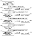
図7には、第2実施形態に係る動作状態報知部50の作動状態(報知フロー)が示されている。第2実施形態の場合、モード切替スイッチ52を押し操作することにより、打撃力を「強」、「中」、「弱」の三段階に切り替えることができる。切り替えられた動作モードは、スピーカ51から音声により使用者に報知される(ステップ1、以下「ST1」と略記する)。以下説明する動作モードの切り替え操作は、トリガ16の引き操作を解除した当該電動工具1の停止状態で行うことができる。   FIG. 7 shows an operating state (notification flow) of the operation state notifying unit 50 according to the second embodiment. In the case of the second embodiment, the hitting force can be switched between three levels of “strong”, “medium”, and “weak” by pressing and operating the mode switch 52. The switched operation mode is notified to the user by voice from the speaker 51 (step 1, hereinafter abbreviated as “ST1”). The operation mode switching operation described below can be performed in a stopped state of the electric power tool 1 after the trigger 16 has been released.

モード切替スイッチ52を1回押し操作すると、現在設定されている動作モードがスピーカ51から音声で報知される(ST2)。音声は、例えば『打撃力「弱」です』に設定されている。この段階で、トリガ16を引き操作すると、電動モータ20が低速(例えば毎分900回転)で起動して弱い打撃力が出力される(ST7)。   When the mode switch 52 is pressed once, the currently set operation mode is notified by sound from the speaker 51 (ST2). The sound is set to, for example, “Impact strength is“ weak ””. At this stage, when the trigger 16 is pulled, the electric motor 20 starts at a low speed (for example, 900 revolutions per minute), and a weak striking force is output (ST7).

動作モードが「弱」の状態で、モード切替スイッチ52を2回連続で押し操作すると、動作モードが「中」に切り替わるとともに、スピーカ51から『打撃力「中」です』と切り替わった動作モードが音声により報知される(ST3)。この段階で、トリガ16を引き操作すると、電動モータ20が中速(例えば毎分1800回転)で起動して中程度の打撃力が出力される(ST8)。   When the mode change switch 52 is pressed twice in succession while the operation mode is “weak”, the operation mode is switched to “medium” and the operation mode that is switched from the speaker 51 to “battering force“ medium ”” It is notified by voice (ST3). At this stage, when the trigger 16 is pulled, the electric motor 20 is activated at a medium speed (for example, 1800 revolutions per minute), and a medium striking force is output (ST8).

動作モード「中」の状態で、再びモード切替スイッチ52を2回連続で押し操作すると、動作モードが「強」に切り替わるとともに、スピーカ51から『打撃力「強」です』と音声により報知される(ST4)。したがってこの段階で、トリガ16を引き操作すると、電動モータ20が高速(例えば毎分2800回転)で起動して強い打撃力が出力される(ST9)。   When the mode switch 52 is pressed twice again in the state of the operation mode “medium”, the operation mode is switched to “strong” and the speaker 51 informs by voice that “battering force is“ strong ””. (ST4). Therefore, when the trigger 16 is pulled at this stage, the electric motor 20 is activated at a high speed (for example, 2800 revolutions per minute) and a strong striking force is output (ST9).

電動モータ20の停止状態で、モード切替スイッチ52を1回だけ押し操作すると、現在の動作モードがスピーカ51から音声で報知される。ST4で動作モードが「強」に切り替わった状態でモード切替スイッチ52を1回だけ押し操作すると、スピーカ51から『打撃力「強」です』との音声で現在の動作モードが報知される(ST5)。   If the mode changeover switch 52 is pressed only once while the electric motor 20 is stopped, the current operation mode is notified by sound from the speaker 51. When the operation mode is switched to “strong” in ST4 and the mode changeover switch 52 is pressed only once, the current operation mode is notified from the speaker 51 with a voice of “strong impact power” (ST5). ).

電動モータ20の停止状態で、モード切替スイッチ52を3回連続して押し操作すると、動作モードが現在の「強」から2段階切り替わって「中」に戻される。これとともに、スピーカ51から『打撃力「中」です』との音声が発せられて切り替わった動作モードが報知される(ST6)。従って、この段階でトリガ16を引き操作すると、電動モータ20が中速で起動して、中程度の打撃力が出力される(ST10)。   When the electric motor 20 is stopped and the mode changeover switch 52 is pressed three times in succession, the operation mode is switched from the current “strong” to two levels and returned to “medium”. At the same time, the speaker 51 issues a sound “battering power“ medium ”” to notify the operation mode switched (ST6). Therefore, when the trigger 16 is pulled at this stage, the electric motor 20 is activated at a medium speed, and a medium striking force is output (ST10).

このように、モード切替スイッチ52の押し操作により動作モード(打撃力)を切り替えると、スピーカ51より発せられる音声により、使用者は動作モードが切り替えられたこと、あるいは現在の動作モードを確認することができる。音声若しくは音による報知によれば使用者は第1実施形態のように動作状態報知部40のように目で見て確認する必要がないので、例えば作業部位を目視しつつ動作モードの切り替えを確実に行うことができ、この点で当該電動工具1の作業性を高めることができる。   As described above, when the operation mode (striking force) is switched by pressing the mode switch 52, the user confirms that the operation mode has been switched or the current operation mode by the sound emitted from the speaker 51. Can do. According to the notification by voice or sound, the user does not need to visually confirm the operation state notification unit 40 as in the first embodiment. In this respect, the workability of the electric power tool 1 can be improved.

第2実施形態の動作状態報知部50は、上記したように工具本体部10の動作モードを音声若しくは音で報知する機能に加えてバッテリパック19の残容量を音声で報知する機能を有している。図8に示すようにモード切替スイッチ52を約2秒間長押しすると、バッテリパック19の残容量がスピーカ51から音声で報知される。音声で報知される内容は、例えば『バッテリパックの残容量は60パーセントです。』、『バッテリパックの残容量が不足しています。充電してください。』に設定されている。   The operation state notifying unit 50 of the second embodiment has a function of notifying the remaining capacity of the battery pack 19 by sound in addition to the function of notifying the operation mode of the tool body 10 by sound or sound as described above. Yes. As shown in FIG. 8, when the mode changeover switch 52 is pressed and held for about 2 seconds, the remaining capacity of the battery pack 19 is notified by sound from the speaker 51. For example, “The remaining capacity of the battery pack is 60%. ”,“ The remaining capacity of the battery pack is insufficient. Please charge. ”Is set.

以上説明したように第2実施形態の動作状態報知部50によれば、工具本体部10の動作モード(打撃力)とバッテリパック19の残容量が音声で報知されることから、使用者は作業部位を目視したまま工具本体部10の動作モードやバッテリパック19の残容量を確認することができ、この点で当該電動工具1の作業性及び使い勝手を高めることができる。   As described above, according to the operation state notifying unit 50 of the second embodiment, the operation mode (blowing force) of the tool main body unit 10 and the remaining capacity of the battery pack 19 are notified by voice. The operating mode of the tool body 10 and the remaining capacity of the battery pack 19 can be confirmed while viewing the site, and the workability and usability of the electric power tool 1 can be improved in this respect.

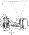
図9には、第3実施形態の電動工具1が示されている。第3実施形態の電動工具1は、工具本体部10の動作モード等の情報を壁面等のスクリーンSに拡大投影して報知するプロジェクタ方式の動作状態報知部60を備えている。第3実施形態の場合、電源部17の上面前側に操作パネル61が設けられている。この操作パネル61では、工具本体部10の動作状態やバッテリパック19の残容量について簡易的に報知される。操作パネル61には、第1実施形態と同じくコントローラ9の制御基板7上に搭載されたLEDを光源とする発光部が設けられている。この発光部の点灯、消滅により工具本体部10の動作モード及びバッテリパック19の残容量等の情報が視覚的に報知される。   FIG. 9 shows a power tool 1 according to the third embodiment. The electric power tool 1 according to the third embodiment includes a projector-type operation state notifying unit 60 that notifies an enlarged projection of information such as an operation mode of the tool body 10 on a screen S such as a wall surface. In the case of the third embodiment, an operation panel 61 is provided on the upper front side of the power supply unit 17. On the operation panel 61, the operating state of the tool body 10 and the remaining capacity of the battery pack 19 are simply notified. As in the first embodiment, the operation panel 61 is provided with a light emitting unit that uses LEDs mounted on the control board 7 of the controller 9 as light sources. Information such as the operation mode of the tool body 10 and the remaining capacity of the battery pack 19 is visually notified by turning on and off the light emitting portion.

第3実施形態の動作状態報知部60では、操作パネル61による簡易な報知に加えて、動作モード等に関する詳細な情報を前方のスクリーンSに投影して報知することができる。電源部17には、前記コントローラ9に加えて投影機63が内装されている。投影機63は、投影部64を備えている。投影部64は、電源部17の前部に組み込まれている。投影機63は動作モード等の各種画像データを投影部64を経て前方へ拡大投影する機能を有している。投影部64から投影された画像は、壁面等のスクリーンSに投影されて、使用者及びその他の者により視覚的に認識することができる。投影機63は、工具本体部10の後面に設けた投影スイッチ62をオン操作することにより起動する。投影機63が起動されると、投影部64から画像が拡大投影されてスクリーンSに表示される。投影機63のオン状態で投影スイッチ62を押し操作(オフ操作)すると、投影機63はオフされて投影画像が消える。   In the operation state notification unit 60 according to the third embodiment, in addition to simple notification by the operation panel 61, detailed information regarding the operation mode and the like can be projected on the front screen S and notified. The power supply unit 17 includes a projector 63 in addition to the controller 9. The projector 63 includes a projection unit 64. The projection unit 64 is incorporated in the front part of the power supply unit 17. The projector 63 has a function of enlarging and projecting various image data such as operation modes forward through the projection unit 64. The image projected from the projection unit 64 is projected on a screen S such as a wall surface, and can be visually recognized by the user and others. The projector 63 is activated by turning on a projection switch 62 provided on the rear surface of the tool body 10. When the projector 63 is activated, an image is enlarged and projected from the projection unit 64 and displayed on the screen S. When the projection switch 62 is pushed (turned off) while the projector 63 is on, the projector 63 is turned off and the projection image disappears.

スクリーンSに投影される情報は、操作パネル61のスイッチ類を操作することにより切り替えることができる。操作パネル61の一例が図10に示されている。この操作パネル61には、切り替えスイッチ68と、3つの発光部65,66,67が配置されている。切り替えスイッチ68は、中央の円形の設定ボタン68aと、その周囲の4つの選択ボタン68bを備えている。上下左右に矢印表示された選択ボタン68bにより表示項目を選択した後、設定ボタン68aを押し操作することにより、選択した表示項目が投影される。3つの発光部65,66,67は前記したように制御基板7上に搭載したLEDを光源とする発光部で、その右側には上から順に「打撃」、「テクス」、「モード」の文字表示がなされている。打撃力設定モードで、「打撃」の文字表示がなされた発光部65が発光する。テクス設定モードで、「テクス」の文字表示がなされた発光部66が発光する。なお、「テクスモード」は、いわゆるテクス用ねじの締め付け作業を想定した動作モードで、ねじ締め当初は高速回転して迅速な締め込みがなされ、ねじ締め負荷が大きくなって打撃が開始されると電動モータ20が自動的に中速回転に切り換わって打撃数(打撃力)が抑制される。ねじ締め最終段階で、打撃力が抑制されることによりねじ折れやいわゆるカムアウトと称されるねじの頭飛びを回避することができる。モード設定モードでは、「モード」の文字表示がなされた発光部67が発光する。使用者は、3つの発光部65,66,67のいずれが発光しているかを目視することによっても、モード切替状態を確認することができる。   Information projected on the screen S can be switched by operating switches on the operation panel 61. An example of the operation panel 61 is shown in FIG. On the operation panel 61, a changeover switch 68 and three light emitting units 65, 66, and 67 are arranged. The changeover switch 68 includes a central circular setting button 68a and four selection buttons 68b around it. After selecting a display item with the selection buttons 68b displayed with arrows on the top, bottom, left, and right, the selected display item is projected by pressing the setting button 68a. The three light emitting portions 65, 66, and 67 are light emitting portions that use LEDs mounted on the control board 7 as a light source as described above, and characters “blow”, “text”, and “mode” are sequentially displayed on the right side from the top. The display is made. In the hitting force setting mode, the light emitting unit 65 on which the character “blow” is displayed emits light. In the text setting mode, the light emitting unit 66 on which the text “Tex” is displayed emits light. “Tex mode” is an operation mode that assumes the so-called tightening operation of the screw for the text, and when the screw is initially tightened, it is rotated at a high speed and fast tightening is performed. The electric motor 20 automatically switches to medium speed rotation, and the number of strikes (blow force) is suppressed. By suppressing the impact force at the final stage of screw tightening, it is possible to avoid screw breakage and so-called cam head skipping. In the mode setting mode, the light emitting unit 67 on which “mode” is displayed emits light. The user can also confirm the mode switching state by observing which of the three light emitting units 65, 66, and 67 is emitting light.

押しボタン式の切り替えスイッチ68は、図11に示すようなジョグダイヤル71a若しくはロータリスイッチと左右の選択ボタン71bを有する切り替えスイッチ71に変更してもよい。この操作パネル70によれば、投影画像の切り替えをより迅速かつ簡便に行うことができる。この操作パネル70にも、「打撃」、「テクス」、「モード」の文字表示がなされた3つの発光部65,66,67が配置されている。   The push button type changeover switch 68 may be changed to a changeover switch 71 having a jog dial 71a or a rotary switch and left and right selection buttons 71b as shown in FIG. According to the operation panel 70, the projection image can be switched more quickly and easily. The operation panel 70 is also provided with three light-emitting portions 65, 66, and 67 on which characters “striking”, “text”, and “mode” are displayed.

第3実施形態では、次のような情報がスクリーンSに投影されるよう投影機63が設定されている。図12に、投影機63の初期画面80が示されている。投影スイッチ62をオン操作するとスクリーンSに先ずこの初期画面80が投影される。この初期画面80では、上から順に「打撃力設定」、「テクス設定」、「ライト設定」、「モード設定」及び「その他設定」を選択することができる。   In the third embodiment, the projector 63 is set so that the following information is projected onto the screen S. FIG. 12 shows an initial screen 80 of the projector 63. When the projection switch 62 is turned on, the initial screen 80 is first projected on the screen S. In this initial screen 80, “battering force setting”, “text setting”, “light setting”, “mode setting”, and “other setting” can be selected in order from the top.

選択ボタン68bで「打撃力設定」を選択した後、設定ボタン68aを押し操作すると、図13に示す打撃力設定用の画面81が投影される。この打撃力設定用画面81で、左向き又は右向き矢印の選択ボタン68bを押し操作することにより打撃力の強弱を変更し、その後設定ボタン68aを押し操作することにより、工具本体部10の打撃力を任意に設定することができる。図13に示す打撃力設定用の画面81では、打撃力を10段階で設定することができる。   When the user presses the setting button 68a after selecting “setting the striking force” with the selection button 68b, a striking force setting screen 81 shown in FIG. 13 is projected. On the striking force setting screen 81, the striking force is changed by pressing the selection button 68b of the leftward or rightward arrow, and then the striking force of the tool body 10 is increased by pressing the setting button 68a. It can be set arbitrarily. In the batting force setting screen 81 shown in FIG. 13, the batting force can be set in 10 stages.

図12に示す初期画面80において、選択ボタン68bで「テクス設定」を選択した後、設定ボタン68aを押し操作すると、図14に示すテクス設定用の画面82が投影される。このテスク設定用画面82では、電動モータ20の「回転スピード」と「打撃検知感度」を設定することができる。上向き又は下向き矢印の選択ボタン68bを押し操作することにより、いずれかを選択することができる。この画面82で電動モータ20の回転スピードと打撃検知感動を設定することにより、テクスねじの締め付け作業において、打撃開始のタイミングと、電動モータ20の変速領域を設定することができる。   In the initial screen 80 shown in FIG. 12, when the “text setting” is selected with the selection button 68b and then the setting button 68a is pressed, a text setting screen 82 shown in FIG. 14 is projected. On this screen setting screen 82, the “rotation speed” and “hit detection sensitivity” of the electric motor 20 can be set. Either one can be selected by pressing the selection button 68b of the upward or downward arrow. By setting the rotation speed and the impact detection feeling of the electric motor 20 on this screen 82, the timing of starting the impact and the speed change region of the electric motor 20 can be set in the tightening operation of the tex screw.

回転スピード設定モードでは、左向き又は右向き矢印の選択ボタン68bを押し操作することにより、電動モータ20の回転スピード(出力回転数)をより高速側若しくは低速側に5段階で選択することができる。選択した回転スピードは、設定ボタン68aを押し操作することにより決定される。   In the rotational speed setting mode, the rotational speed (output rotational speed) of the electric motor 20 can be selected in five steps, higher speed or lower speed, by pressing the left or right arrow selection button 68b. The selected rotation speed is determined by pressing the setting button 68a.

打撃検知感度設定モードでは、左向き又は右向き矢印の選択ボタン68bを押し操作することにより、電動モータ20への供給電流(ねじ締め負荷)の検知感度を変更して打撃動作開始及び停止のタイミングを変更することができる。5段階で検知感度を高くし、逆に低く選択した後、設定ボタン68aを押し操作すると、打撃力開始、停止のタイミングを決定するねじ締め負荷検知感度を任意に変更することができる。   In the impact detection sensitivity setting mode, pressing the left or right arrow selection button 68b changes the detection sensitivity of the supply current (screw tightening load) to the electric motor 20 and changes the timing of starting and stopping the impact operation. can do. When the detection sensitivity is increased in five stages and the setting button 68a is pressed after the detection sensitivity is selected to be lower, the screw tightening load detection sensitivity for determining the timing of starting and stopping the striking force can be arbitrarily changed.

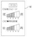
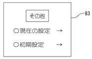
図12に示す初期画面80において、選択ボタン68bで「その他設定」を選択した後、設定ボタン68aを押し操作すると、図15に示すその他設定用の画面83が投影される。この画面83では、「現在の設定」と「初期設定」を選択することができる。選択ボタン68bで「現在の設定」を選択した後、設定ボタン68aを押し操作すると、図16に示す「現在の設定」画面84が投影される。この「現在の設定」画面84では、回転打撃機構32による打撃力と、電動モータ20の回転スピード(テクススピード)と、ねじ締め負荷の検知感度(テクス感度)について現在の設定状態がそれぞれ段階表示される。図16に示す「現在の設定」画面84では、打撃力が10段階中の9段階(打撃力強)に設定され、電動モータ20の回転スピードが5段階中の3段階(中速)に設定され、ねじ締め負荷の検知感度が5段階中の2段階(低感度)に設定されていることが報知されている。   In the initial screen 80 shown in FIG. 12, after selecting “other setting” with the selection button 68b, when the setting button 68a is pressed, a screen 83 for other setting shown in FIG. 15 is projected. On this screen 83, “current setting” and “initial setting” can be selected. When “current setting” is selected with the selection button 68b and then the setting button 68a is pressed, a “current setting” screen 84 shown in FIG. 16 is projected. In the “current setting” screen 84, the current setting states of the striking force by the rotary striking mechanism 32, the rotational speed (text speed) of the electric motor 20, and the detection sensitivity (text sensitivity) of the screw tightening load are displayed in stages. Is done. In the “current setting” screen 84 shown in FIG. 16, the striking force is set to 9 steps (strong striking force) in 10 steps, and the rotation speed of the electric motor 20 is set to 3 steps (medium speed) out of 5 steps. Then, it is reported that the detection sensitivity of the screw tightening load is set to 2 out of 5 levels (low sensitivity).

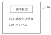
選択ボタン68bで「初期設定」を選択した後、設定ボタン68aを押し操作すると、図17に示す「初期設定」画面85が投影される。この「初期設定」画面85では、工具本体部10の各種動作モードを初期設定に戻すことができる。上下矢印表示の選択ボタン68bで「初期設定に戻す」を選択した後、設定ボタン68aを押し操作すると、工具本体部10の動作モードがすべて初期設定値に戻される。「キャンセル」を選択した後、設定ボタン68aを押し操作すると、各種動作モードはそのまま維持されて初期化されず、画面は図15に示す「その他」設定用の画面83に戻される。   When “Initial setting” is selected with the selection button 68b and then the setting button 68a is pressed, an “Initial setting” screen 85 shown in FIG. 17 is projected. On this “initial setting” screen 85, various operation modes of the tool body 10 can be returned to the initial settings. When “return to initial setting” is selected with the selection button 68b of the up / down arrow display and the setting button 68a is pressed, all the operation modes of the tool body 10 are returned to the initial setting values. When the user presses the setting button 68a after selecting “Cancel”, the various operation modes are maintained and are not initialized, and the screen is returned to the “other” setting screen 83 shown in FIG.

図12に示す初期画面80で「ライト設定」を選択して設定ボタン68aを押し操作すると、ライト設定画面が投影される。このライト設定画面では、照明具5の点灯、消灯を行うことができる。同じく初期画面80で「モード設定」を選択して設定ボタン68aを押し操作すると、工具本体部10の動作モードを変更するための画面が投影される。このモード変更画面では、打撃力の強弱、打撃開始、停止のタイミング、電動モータの回転スピード等について、各種作業に合わせて最適に設定された複数の専用モードが表示され、使用者はそのうちから任意に選択することにより工具本体部10の動作モードを簡単に変更することができる。スクリーンSに投影した各画面は、投影スイッチ62をオフ操作して投影機63を停止させれば消される。   When “light setting” is selected on the initial screen 80 shown in FIG. 12 and the setting button 68a is pressed, a light setting screen is projected. On this light setting screen, the lighting fixture 5 can be turned on and off. Similarly, when “mode setting” is selected on the initial screen 80 and the setting button 68a is pressed, a screen for changing the operation mode of the tool body 10 is projected. This mode change screen displays multiple dedicated modes that are optimally set for various tasks, such as the strength of the impact force, the timing for starting and stopping the impact, and the rotation speed of the electric motor. It is possible to easily change the operation mode of the tool body 10 by selecting. Each screen projected on the screen S is erased when the projection switch 62 is turned off to stop the projector 63.

以上説明したように第3実施形態の動作状態報知部60によれば、工具本体部10の動作モード等に関する各種の情報が投影機63によってスクリーンSに拡大投影される。当該電動工具1の限られたスペースではなく、壁面等の大型のスクリーンSに視覚的に報知することから、より多くの文字情報等を見やすい大きさで表示することができ、これにより当該電動工具1の操作性及び機能性をより高めることができる。   As described above, according to the operation state notification unit 60 of the third embodiment, various types of information related to the operation mode and the like of the tool body unit 10 are enlarged and projected on the screen S by the projector 63. Since the power tool 1 is not limited to a limited space but is visually notified on a large screen S such as a wall surface, more character information can be displayed in a size that is easy to see. The operability and functionality of 1 can be further enhanced.

スクリーンSには、作業場の壁面のほか、天板部(天井)、床面、あるいは車両のボディやウインド等の比較的平坦な面を適宜その場の状況に合わせて活用することができ、この点で動作状態報知部60の使い勝手を高めることができる。また、前方のスクリーンSに投影して報知する構成であるので、使用者は作業姿勢をそのままほぼ維持した状態で電動工具1の動作モードを変更、確認することができ、この点で電動工具1の作業性を高めることができる。   In addition to the wall surface of the workplace, the screen S can utilize a relatively flat surface such as a top plate (ceiling), a floor surface, or a vehicle body or window according to the situation of the site. The usability of the operation state notification unit 60 can be enhanced in terms of points. Moreover, since it is the structure which projects on the screen S ahead and alert | reports, the user can change and confirm the operation mode of the electric tool 1 in the state which maintained the working posture as it is, and the electric tool 1 in this respect Workability can be improved.

また、第3実施形態の動作状態報知部60によれば、当該電動工具1の大きさに制限されることなく、大きな画面で多くの情報を報知することができる。   Moreover, according to the operation state alerting | reporting part 60 of 3rd Embodiment, many information can be alert | reported on a big screen, without being restrict | limited to the magnitude | size of the said electric tool 1. FIG.

さらに、第3実施形態の動作状態報知部60によれば、衝撃等に弱いディスプレイを備える構成ではないことから、結果として当該電動工具1の耐久性を高めることができる。   Furthermore, according to the operation state notification unit 60 of the third embodiment, since the configuration is not provided with a display that is weak against impact or the like, the durability of the electric power tool 1 can be improved as a result.

以上例示した第1実施形態に係る多色LED方式の動作状態報知部40、第2実施形態に係る音声方式の動作状態報知部50、第3実施形態に係るプロジェクタ方式の動作状態報知部50を適宜組み合わせて適用する構成としてもよい。また、既存の表示パネルに音声方式やプロジェクタ方式の動作状態報知部40,50を組み合わせることもできる。   The multicolor LED operation state notification unit 40 according to the first embodiment exemplified above, the sound operation state notification unit 50 according to the second embodiment, and the projector operation state notification unit 50 according to the third embodiment. It is good also as a structure applied combining suitably. In addition, the sound type or projector type operation state notifying units 40 and 50 can be combined with an existing display panel.

また、電動工具1として回転打撃工具(インパクトドライバ)を例示したが、孔明け工具や切断工具等のその他の電動工具について例示した第1〜第3実施形態の動作状態報知部40,50,60を適用することができる。   Moreover, although the rotary impact tool (impact driver) was illustrated as the electric tool 1, the operation state notification units 40, 50, 60 of the first to third embodiments illustrated for other electric tools such as a drilling tool and a cutting tool. Can be applied.

さらに、バッテリパック19を電源とする充電式の電動工具1を例示したが、例えば商用100Vを電源とする交流電源式の電動工具についても同様に適用することができる。   Furthermore, although the rechargeable electric power tool 1 using the battery pack 19 as a power source has been illustrated, for example, the present invention can be similarly applied to an AC power type electric power tool using a commercial 100V power source.

1…電動工具(インパクトドライバ)
2…ねじ(半割りケース結合用)
3…ハンドストラップ
4…フック
5…照明具(LED)、5a…透明カバー
6…切り替えスイッチ
7…制御基板、7a…コンデンサ、7b…スイッチ本体
7c…LED(第1発光部)、7d…LED(第2発光部)
8…ケース
9…コントローラ
10…工具本体部
11…本体ケース
12…後部ケース
12a…軸受保持部
15…グリップ部
16…トリガ
17…電源部
18…メインスイッチ
19…バッテリパック
J…出力軸線
20…電動モータ
21…固定子
22…回転子
23…センサ基板
24…モータ軸
25…軸受(前側)
26…軸受(後ろ側)
27…中間区画壁
28…冷却ファン
30…遊星歯車機構
31…駆動軸、31a…溝部
32…回転打撃機構
32a…ハンマー、32b…圧縮ばね、32c…鋼球
33…アンビル
34…ころ軸受
35…工具保持部
36…出力軸
40…動作状態報知部(第1実施形態)
41…モード切替スイッチ、41a…作動部
42…第1発光部、42a…導光部
43…第2発光部、43a…導光部
50…動作状態報知部(第2実施形態)
51…スピーカ
52…モード切替スイッチ
60…動作状態報知部(第3実施形態)
61…操作パネル
62…投影スイッチ
63…投影機
64…投影部
S…スクリーン
65,66,67…発光部
68…切り替えスイッチ、68a…設定ボタン、68b…選択ボタン
71…切り替えスイッチ、71a…ジョグダイヤル、71b…選択ボタン
80…初期画面
81…画面(打撃力設定用)
82…画面(テクス設定用)
83…画面(その他設定用)
84…画面(現在の設定表示用)
85…画面(初期設定用)
1 ... Electric tool (impact driver)
2 ... Screw (for split case connection)
3 ... Hand strap 4 ... Hook 5 ... Illuminator (LED), 5a ... Transparent cover 6 ... Changeover switch 7 ... Control board, 7a ... Capacitor, 7b ... Switch body 7c ... LED (first light emitting unit), 7d ... LED ( (Second light emitting part)
8 ... Case 9 ... Controller 10 ... Tool body 11 ... Main body case 12 ... Rear case 12a ... Bearing holding part 15 ... Grip part 16 ... Trigger 17 ... Power source 18 ... Main switch 19 ... Battery pack J ... Output axis 20 ... Electric Motor 21 ... Stator 22 ... Rotor 23 ... Sensor substrate 24 ... Motor shaft 25 ... Bearing (front side)
26 ... Bearing (rear side)
27 ... Intermediate partition wall 28 ... Cooling fan 30 ... Planetary gear mechanism 31 ... Drive shaft, 31a ... Groove 32 ... Rotary striking mechanism 32a ... Hammer, 32b ... Compression spring, 32c ... Steel ball 33 ... Anvil 34 ... Roller bearing 35 ... Tool Holding unit 36 ... output shaft 40 ... operating state notification unit (first embodiment)
41 ... Mode changeover switch, 41a ... Actuator 42 ... First light emitter, 42a ... Light guide 43 ... Second light emitter, 43a ... Light guide 50 ... Operational status notifier (second embodiment)
51 ... Speaker 52 ... Mode changeover switch 60 ... Operational state notification unit (third embodiment)
61 ... Operation panel 62 ... Projection switch 63 ... Projector 64 ... Projection unit S ... Screens 65, 66, 67 ... Light emitting unit 68 ... Changeover switch, 68a ... Setting button, 68b ... Selection button 71 ... Changeover switch, 71a ... Jog dial, 71b ... selection button 80 ... initial screen 81 ... screen (for hitting force setting)
82 ... Screen (for text setting)
83 ... screen (for other settings)
84 ... screen (for current setting display)
85 ... screen (for initial setting)

Claims (5)

電動モータを駆動源として動作する工具本体部と、該工具本体部の動作状態をLEDの発光色を変化させて報知する動作状態報知部を備えた電動工具。 An electric tool comprising a tool main body that operates using an electric motor as a drive source, and an operation state notifying unit that notifies the operation state of the tool main body by changing the emission color of the LED. 請求項1記載の電動工具であって、前記動作状態報知部は、前記電動モータの出力を切り替える切替スイッチと、前記電動モータの出力をLEDの発光色を変化させて報知する発光部を備えた電動工具。 2. The electric tool according to claim 1, wherein the operation state notifying unit includes a changeover switch that switches an output of the electric motor, and a light emitting unit that notifies the output of the electric motor by changing an emission color of an LED. Electric tool. 電動モータを駆動源として動作する工具本体部と、該工具本体部の動作状態を音で報知する動作状態報知部を備えた電動工具。 An electric tool comprising a tool main body that operates using an electric motor as a drive source, and an operation state notifying unit that notifies the operation state of the tool main body by sound. 請求項3記載の電動工具であって、使用者が把持するグリップ部を備えており、該グリップ部に前記音を発するスピーカを内装し、前記工具本体部の後面に設けた切り替えスイッチの操作により前記工具本体部の動作状態を切り替えると、当該動作状態が前記スピーカから発せられる音により報知される構成とした電動工具。 The electric tool according to claim 3, further comprising a grip portion that is gripped by a user, a speaker that emits the sound in the grip portion, and an operation of a changeover switch provided on a rear surface of the tool body portion. When the operation state of the tool main body is switched, the electric tool is configured such that the operation state is notified by sound emitted from the speaker. 電動モータを駆動源として動作する工具本体部と、該工具本体部の動作状態に関する情報をスクリーン上に拡大投影して報知する動作状態報知部を備えた電動工具。
An electric tool comprising: a tool main body that operates using an electric motor as a drive source; and an operation state notifying unit that projects and reports information on the operation state of the tool main body on a screen.
JP2016007942A 2016-01-19 2016-01-19 Electric power tool Pending JP2017127916A (en)

Priority Applications (1)

Application Number Priority Date Filing Date Title
JP2016007942A JP2017127916A (en) 2016-01-19 2016-01-19 Electric power tool

Applications Claiming Priority (1)

Application Number Priority Date Filing Date Title
JP2016007942A JP2017127916A (en) 2016-01-19 2016-01-19 Electric power tool

Publications (2)

Publication Number Publication Date
JP2017127916A true JP2017127916A (en) 2017-07-27
JP2017127916A5 JP2017127916A5 (en) 2018-12-27

Family

ID=59395230

Family Applications (1)

Application Number Title Priority Date Filing Date
JP2016007942A Pending JP2017127916A (en) 2016-01-19 2016-01-19 Electric power tool

Country Status (1)

Country Link
JP (1) JP2017127916A (en)

Cited By (5)

* Cited by examiner, † Cited by third party
Publication number Priority date Publication date Assignee Title
WO2019193979A1 (en) * 2018-04-04 2019-10-10 パナソニックIpマネジメント株式会社 Electric tool
WO2020071275A1 (en) * 2018-10-01 2020-04-09 工機ホールディングス株式会社 Power equipment
CN111421511A (en) * 2019-01-10 2020-07-17 株式会社牧田 Electric tool
WO2021220992A1 (en) * 2020-04-28 2021-11-04 工機ホールディングス株式会社 Work machine
US11911881B2 (en) 2019-08-06 2024-02-27 Makita Corporation Driver-drill

Citations (6)

* Cited by examiner, † Cited by third party
Publication number Priority date Publication date Assignee Title
JP2006120395A (en) * 2004-10-20 2006-05-11 Matsushita Electric Ind Co Ltd Push-on switch
JP2011000654A (en) * 2009-06-16 2011-01-06 Hitachi Koki Co Ltd Power tool
JP2011109799A (en) * 2009-11-17 2011-06-02 Max Co Ltd Remaining capacity display method of battery in charging tool
JP2011204486A (en) * 2010-03-25 2011-10-13 Seiko Epson Corp Switch mechanism, electronic equipment, and printer
JP2012139747A (en) * 2010-12-28 2012-07-26 Hitachi Koki Co Ltd Power tool
JP2014073535A (en) * 2012-10-02 2014-04-24 Makita Corp Electric tool

Patent Citations (6)

* Cited by examiner, † Cited by third party
Publication number Priority date Publication date Assignee Title
JP2006120395A (en) * 2004-10-20 2006-05-11 Matsushita Electric Ind Co Ltd Push-on switch
JP2011000654A (en) * 2009-06-16 2011-01-06 Hitachi Koki Co Ltd Power tool
JP2011109799A (en) * 2009-11-17 2011-06-02 Max Co Ltd Remaining capacity display method of battery in charging tool
JP2011204486A (en) * 2010-03-25 2011-10-13 Seiko Epson Corp Switch mechanism, electronic equipment, and printer
JP2012139747A (en) * 2010-12-28 2012-07-26 Hitachi Koki Co Ltd Power tool
JP2014073535A (en) * 2012-10-02 2014-04-24 Makita Corp Electric tool

Cited By (13)

* Cited by examiner, † Cited by third party
Publication number Priority date Publication date Assignee Title
WO2019193979A1 (en) * 2018-04-04 2019-10-10 パナソニックIpマネジメント株式会社 Electric tool
WO2020071275A1 (en) * 2018-10-01 2020-04-09 工機ホールディングス株式会社 Power equipment
JP7210291B2 (en) 2019-01-10 2023-01-23 株式会社マキタ electric driver drill
JP2020110864A (en) * 2019-01-10 2020-07-27 株式会社マキタ Electric power tool
CN111421511A (en) * 2019-01-10 2020-07-17 株式会社牧田 Electric tool
JP2023029579A (en) * 2019-01-10 2023-03-03 株式会社マキタ Electric tool or gardening tool
JP7395035B2 (en) 2019-01-10 2023-12-08 株式会社マキタ Power tools or gardening tools
CN111421511B (en) * 2019-01-10 2024-01-12 株式会社牧田 Electric tool
US11890730B2 (en) 2019-01-10 2024-02-06 Makita Corporation Power tool
US11911881B2 (en) 2019-08-06 2024-02-27 Makita Corporation Driver-drill
WO2021220992A1 (en) * 2020-04-28 2021-11-04 工機ホールディングス株式会社 Work machine
JPWO2021220992A1 (en) * 2020-04-28 2021-11-04
JP7332039B2 (en) 2020-04-28 2023-08-23 工機ホールディングス株式会社 work machine

Similar Documents

Publication Publication Date Title
US10906163B2 (en) Power tool
JP2017127916A (en) Electric power tool
JP6768751B2 (en) Electric tool
JP7337873B2 (en) impact tools and power tools
US7029142B2 (en) Power tool
EP2716412B1 (en) Electric power tool
JP2014148001A (en) Power tool
JP2017209760A (en) Electric tool
JP2019107710A (en) Electrical equipment
JP5709087B2 (en) Electric tool
JP5937940B2 (en) Electric tool
JP2018043372A (en) Portable processor
JP6417250B2 (en) Electric tool
JP6013929B2 (en) Electric tool
JP2018008356A (en) Power tool
JP2014073535A (en) Electric tool
JP6138997B2 (en) Electric tool
WO2021220992A1 (en) Work machine
JP2017148910A (en) Electric tool
JP5937479B2 (en) Electric tool
JP2020196052A (en) Electric tool
JP2008062344A (en) Power tool
US20230043839A1 (en) Driver drill
US20240058937A1 (en) Electric work machine
JP2023020813A (en) Electric tool and impact driver

Legal Events

Date Code Title Description
A521 Request for written amendment filed

Free format text: JAPANESE INTERMEDIATE CODE: A523

Effective date: 20181115

A621 Written request for application examination

Free format text: JAPANESE INTERMEDIATE CODE: A621

Effective date: 20181115

A977 Report on retrieval

Free format text: JAPANESE INTERMEDIATE CODE: A971007

Effective date: 20191024

A131 Notification of reasons for refusal

Free format text: JAPANESE INTERMEDIATE CODE: A131

Effective date: 20191029

A521 Request for written amendment filed

Free format text: JAPANESE INTERMEDIATE CODE: A523

Effective date: 20191227

A131 Notification of reasons for refusal

Free format text: JAPANESE INTERMEDIATE CODE: A131

Effective date: 20200204

A521 Request for written amendment filed

Free format text: JAPANESE INTERMEDIATE CODE: A523

Effective date: 20200316

A02 Decision of refusal

Free format text: JAPANESE INTERMEDIATE CODE: A02

Effective date: 20200526