JP3164635U - Motor stator heat dissipation structure of heat dissipation fan - Google Patents
Motor stator heat dissipation structure of heat dissipation fan Download PDFInfo
- Publication number
- JP3164635U JP3164635U JP2010006418U JP2010006418U JP3164635U JP 3164635 U JP3164635 U JP 3164635U JP 2010006418 U JP2010006418 U JP 2010006418U JP 2010006418 U JP2010006418 U JP 2010006418U JP 3164635 U JP3164635 U JP 3164635U
- Authority
- JP
- Japan
- Prior art keywords
- silicon iron
- iron piece
- heat
- motor stator
- heat dissipating
- Prior art date
- Legal status (The legal status is an assumption and is not a legal conclusion. Google has not performed a legal analysis and makes no representation as to the accuracy of the status listed.)
- Expired - Fee Related
Links
- 230000017525 heat dissipation Effects 0.000 title claims abstract description 28
- XWHPIFXRKKHEKR-UHFFFAOYSA-N iron silicon Chemical compound [Si].[Fe] XWHPIFXRKKHEKR-UHFFFAOYSA-N 0.000 claims abstract description 62
- 238000009413 insulation Methods 0.000 description 3
- 238000006243 chemical reaction Methods 0.000 description 1
- 230000000694 effects Effects 0.000 description 1
Images


Landscapes
- Motor Or Generator Cooling System (AREA)
Abstract
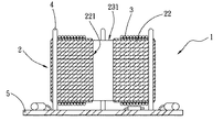
【課題】珪素鉄片とコイルユニットの温度を低下させ、放熱ファンの特性を高める。【解決手段】放熱ファンに適用するモーター固定子放熱構造であって、積み重ねた複数の珪素鉄片21からなる珪素鉄片ユニット2、及び各珪素鉄片21に接続して設置されたヒートパイプ4からなり、各珪素鉄片21の磁極22は重なって柱状の磁極221を形成し、磁極柱221にはコイルユニット3を巻き付け、ヒートパイプ4は珪素鉄片21とコイルユニット3の熱を伝導し、これにより珪素鉄片21とコイルユニット3の温度を低下させ、放熱ファンの特性を高めることができる。【選択図】図1The temperature of a silicon iron piece and a coil unit is lowered to improve the characteristics of a heat dissipation fan. A motor stator heat dissipating structure applied to a heat dissipating fan, comprising a silicon iron piece unit 2 composed of a plurality of silicon iron pieces 21 stacked, and a heat pipe 4 connected to each silicon iron piece 21; The magnetic poles 22 of each silicon iron piece 21 overlap to form a columnar magnetic pole 221, and the coil unit 3 is wound around the magnetic pole pillar 221, and the heat pipe 4 conducts the heat of the silicon iron piece 21 and the coil unit 3. The temperature of 21 and the coil unit 3 can be lowered, and the characteristics of the heat dissipation fan can be improved. [Selection] Figure 1
Description
本考案はモーター固定子放熱構造に関し、特に珪素鉄片とコイルユニットの温度を低下させ、放熱ファンの特性を高めることができるモーター固定子放熱構造に関する。 The present invention relates to a motor stator heat dissipating structure, and more particularly to a motor stator heat dissipating structure that can reduce the temperature of a silicon iron piece and a coil unit and improve the characteristics of a heat dissipating fan.
近年、電子産業の急速な発展により、電子パーツの性能は急速に向上しており、演算処理速度もどんどん高速化している。
内部のチップユニットの演算速度も上昇を続けており、チップ数も増え続けているため、チップ作動時に発する熱も、それに伴い増加している。
もし、これらの熱を即時に発散させることができなければ、電子パーツの性能に大きく影響し、電子パーツの演算処理速度は低下し、熱がたまり続ければ、電子パーツがショートする恐れもあるため、放熱は今や電子パーツにおける重要な課題の一つとなっている。
In recent years, due to the rapid development of the electronic industry, the performance of electronic parts has been rapidly improved, and the processing speed has also been increased.
Since the calculation speed of the internal chip unit continues to increase and the number of chips continues to increase, the heat generated during chip operation increases accordingly.
If these heat cannot be dissipated immediately, the performance of the electronic parts will be greatly affected, the calculation processing speed of the electronic parts will decrease, and if the heat continues to accumulate, the electronic parts may be short-circuited. Heat dissipation is now one of the important issues in electronic parts.
放熱ファンは、放熱フィンユニットが吸收した熱を迅速に排除し、循環させる効果が良好であるため、放熱装置において、放熱ファンはなくてはならないパーツの一つとなっている。 Since the heat dissipation fan has a good effect of quickly removing and circulating the heat absorbed by the heat dissipation fin unit, the heat dissipation fan is one of the essential parts in the heat dissipation device.
従来の放熱ファン構造は、固定子ユニット、該固定子ユニット片側に設置するローターユニット、該固定子ユニットの反対の片側に設置するファン回路板からなる。
該固定子ユニットは、珪素鉄片ユニットを備え、該珪素鉄片ユニットは、外へと磁極柱を延長する。
該磁極柱上には、コイルユニットが巻き付く。
該コイルユニットは同時に、該ファン回路板と該ファン回路板上に設置する電子パーツに電気的に接続する。
よって、該放熱ファン構造の駆動時には、該ファン回路板と該電子パーツとは電気的に導通し、電気的に導通する時には、該電子パーツは、該磁極柱上のコイルユニットを駆動する。
該ローターユニットは、該コイルユニットに磁極が発生することで回転し、該電子パーツが該コイルユニットの磁極を駆動する時には、該コイルユニットと該珪素鉄片ユニットは、発熱して温度が上昇する。
しかし、該放熱ファンは、該コイルユニット及び該珪素鉄片ユニット周辺に、放熱に用いることができる装置を設置しないため、該コイルユニットの熱はたまるばかりで外へと排除されない。
これでは、放熱ファンの作動性能に影響を及ぼし、しかも放熱ファンの放熱特性を効果的に発揮することができない。
A conventional heat dissipation fan structure includes a stator unit, a rotor unit installed on one side of the stator unit, and a fan circuit board installed on the opposite side of the stator unit.
The stator unit includes a silicon iron piece unit, and the silicon iron piece unit extends the magnetic pole column to the outside.
A coil unit is wound on the magnetic pole column.
At the same time, the coil unit is electrically connected to the fan circuit board and electronic parts installed on the fan circuit board.
Therefore, when the heat radiating fan structure is driven, the fan circuit board and the electronic part are electrically connected, and when electrically connected, the electronic part drives the coil unit on the magnetic pole column.
The rotor unit rotates by generating a magnetic pole in the coil unit, and when the electronic part drives the magnetic pole of the coil unit, the coil unit and the silicon iron piece unit generate heat and the temperature rises.
However, since the heat dissipating fan is not provided with a device that can be used for heat dissipating around the coil unit and the silicon iron piece unit, the heat of the coil unit is accumulated and is not excluded to the outside.
This affects the operating performance of the heat radiating fan and cannot effectively exhibit the heat radiating characteristics of the heat radiating fan.
上記したように、従来の放熱ファンは、以下の欠点を備える。
1.コイルユニット及び珪素鉄片ユニットの熱を効果的に排除することができない。
2.放熱ファンの作動性能に影響を及ぼす。
3.放熱ファンの放熱特性を効果的に発揮することができない。
本考案は、従来の放熱ファンの上記した欠点に鑑みてなされたものである。
As described above, the conventional heat radiating fan has the following drawbacks.
1. The heat of the coil unit and the silicon iron piece unit cannot be effectively eliminated.
2. Affects the operating performance of the heat dissipation fan.
3. The heat dissipation characteristics of the heat dissipation fan cannot be exhibited effectively.
The present invention has been made in view of the above-described drawbacks of conventional heat dissipating fans.
本考案が解決しようとする第一の課題は、珪素鉄片ユニット及びコイルユニットの温度を低下させられるモーター固定子放熱構造を提供することである。
本考案が解決しようとする第二の課題は、可放熱ファンの特性を高めることができるモーター固定子放熱構造を提供することである。
The first problem to be solved by the present invention is to provide a motor stator heat dissipation structure that can reduce the temperature of the silicon iron piece unit and the coil unit.
The second problem to be solved by the present invention is to provide a motor stator heat dissipating structure capable of improving the characteristics of the heat dissipating fan.
上記課題を解決するため、本考案は下記のモーター固定子放熱構造を提供する。
モーター固定子放熱構造は、放熱ファンに応用し、複数の珪素鉄片を備える珪素鉄片ユニット、及び該各珪素鉄片に接続して設置する少なくとも1個のヒートパイプからなり、
該各珪素鉄片相互に重なり、該珪素鉄片は、外へと複数の磁極を延伸し、該各珪素鉄片の磁極と磁極は重なって磁極柱を形成し、
該各磁極柱には、少なくとも1個のコイルユニットを巻き付けて設置し、
該ヒートパイプは、該珪素鉄片とコイルユニットの熱を伝導し、
こうして、該珪素鉄片と該コイルユニットとの温度を低下させ、同時に放熱ファンの放熱特性を向上させることができる。
In order to solve the above problems, the present invention provides the following motor stator heat dissipation structure.
The motor stator heat dissipation structure is applied to a heat dissipation fan, and includes a silicon iron piece unit including a plurality of silicon iron pieces, and at least one heat pipe connected to each silicon iron piece,
The silicon iron pieces overlap each other, the silicon iron pieces extend a plurality of magnetic poles to the outside, and the magnetic poles and magnetic poles of the silicon iron pieces overlap to form a magnetic pole column,
At least one coil unit is wound around each magnetic pole and installed,
The heat pipe conducts heat of the silicon iron piece and the coil unit,
Thus, the temperature of the silicon iron piece and the coil unit can be lowered, and at the same time, the heat dissipation characteristics of the heat dissipation fan can be improved.
本考案のモーター固定子放熱構造は、珪素鉄片とコイルユニットの温度を低下させ、放熱ファンの作動性能を高め、放熱ファンの特性を効果的に発揮させることができる。 The motor stator heat dissipation structure of the present invention can reduce the temperature of the silicon iron piece and the coil unit, improve the operation performance of the heat dissipation fan, and effectively exhibit the characteristics of the heat dissipation fan.
以下に図面を参照しながら本考案を実施するための最良の形態について詳細に説明する。 The best mode for carrying out the present invention will be described below in detail with reference to the drawings.
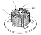
図1、2、3に示すように、本考案モーター固定子放熱構造第一実施例は、放熱ファンに応用する。 As shown in FIGS. 1, 2, and 3, the motor stator heat dissipation structure first embodiment of the present invention is applied to a heat dissipation fan.
モーター固定子1は、珪素鉄片ユニット2、少なくとも1個のヒートパイプ4及び少なくとも1個のファン回路板5からなる。
The
該珪素鉄片ユニット2は、複数の珪素鉄片21を備え、該各珪素鉄片21の中心位置には、孔洞23を設ける。各珪素鉄片21の中心から放射状に延長した端部には、拡大部24を形成する。
The silicon
該各珪素鉄片21は積み重なり、該珪素鉄片ユニット2を形成する。
The
該珪素鉄片21が相互に重なって該各珪素鉄片21の磁極22が相互に重なり、磁極柱221を形成する。
The
該各孔洞23は、空気流通道231を形成し、また、各珪素鉄片21には該孔洞23を設けた中心から放射状に延長した端部に拡大した拡大部24に形成し、珪素鉄片を重ねた磁極端部241を形成する。
Each hole 23 forms an
該珪素鉄片ユニット2の上下両面には絶縁25を設けて、該絶縁部25を介してコイルユニット3を巻回する。
ヒートパイプ4は、該珪素鉄片ユニット2に接して該コイルユニット3と該珪素鉄片ユニット2の熱を伝導する。
The
ファン回路板5は、該珪素鉄片ユニット2片面に相対して接して該コイルユニット3に電気的に接続し、該ファン回路板5上には、電子パーツ51を設置する。
The
該ヒートパイプ4は、該珪素鉄片ユニット2に接するが、本実施例中では、該各ヒートパイプ4は、該各磁極端部241にそれぞれ配置する。
The
該ファン回路板5と該電子パーツ51とが電気的に導通すると、該ファン回路板5と該電子パーツ51とは、該コイルユニット3を介して該珪素鉄片ユニット2により磁極22として作動する。
When the
磁極22が作動すると同時に、該コイルユニット3と該珪素鉄片ユニット2が発熱して温度が上昇し、発生した熱が堆積する現象が発生する。
Simultaneously with the operation of the
該磁極端部241のヒートパイプ4は、該珪素鉄片ユニット2と該コイルユニット3の熱を吸収して放熱し、該コイルユニット3と該珪素鉄片ユニット2との温度を低下させ、同時に放熱ファンの放熱特性を向上させることができる。
The
図4、5に示すように、本考案第二実施例において、その全体構造及びパーツ間の連結関係は、おおよそ上記した前実施例と共通であるため、共通点については説明しない。 As shown in FIGS. 4 and 5, in the second embodiment of the present invention, the overall structure and the connection relationship between the parts are approximately the same as those in the previous embodiment, and common points will not be described.
本実施例と上記した前実施例との相違点は、該ヒートパイプ4は該珪素鉄片ユニット2に接続し、同時に該ファン回路板5に組み合わせて設置する点である。
The difference between the present embodiment and the previous embodiment described above is that the
これにより、該ファン回路板5と電子パーツ51とは、電気的に導通し、該電子パーツ51が熱エネルギーを発生すると、該ヒートパイプ4は、該電子パーツ51の熱エネルギーを併せて導出し、該ファン回路板5の発熱電子パーツ51の温度を低下させる。
Thereby, the
図6、7に示すように、本考案第三実施例において、その全体構造及びパーツ間の連結関係は、おおよそ上記した前実施例と共通であるため、共通点については説明しない。 As shown in FIGS. 6 and 7, in the third embodiment of the present invention, the overall structure and the connection relationship between the parts are approximately the same as those in the previous embodiment, and common points will not be described.
本実施例と上記した前実施例との相違点は、該ヒートパイプ4は、該珪素鉄片ユニット2に通して設置し、かつ、該空気流通道231に近接する点である。
The difference between the present embodiment and the previous embodiment described above is that the
該空気流通道231に近接する珪素鉄片ユニット2は、該珪素鉄片ユニット2と該コイルユニット3の熱を吸収して放熱し、該コイルユニット3と該珪素鉄片ユニット2との温度を低下させる。
The silicon
図8、9に示すように、は、本考案第四実施例において、該ヒートパイプ4は、該珪素鉄片ユニット2に通して設置し、該空気流通道231において露出する。
As shown in FIGS. 8 and 9, in the fourth embodiment of the present invention, the
該空気流通道231内に露出するヒートパイプ4は、該珪素鉄片ユニット2と該コイルユニット3の熱エネルギーを吸収して放熱し、同時に露出部分を通して、それが伝導する熱エネルギーを放熱することができる。
The
上記の本考案名称と内容は、本考案技術内容の説明に用いたのみで、本考案を限定するものではない。本考案の精神に基づく等価応用或いは部品(構造)の転換、置換、数量の増減はすべて、本考案の保護範囲に含むものとする。 The names and contents of the present invention described above are only used for explaining the technical contents of the present invention, and do not limit the present invention. Equivalent applications based on the spirit of the present invention, conversion of parts (structure), replacement, increase / decrease in quantity are all included in the protection scope of the present invention.
本考案は実用新案登録の要件である新規性を備え、従来の同類製品に比べ十分な進歩を有し、実用性が高く、社会のニーズに合致しており、産業上の利用価値は非常に大きい。 The present invention has the novelty that is a requirement for utility model registration, has sufficient progress compared to similar products of the past, has high practicality, meets the needs of society, and has a very high industrial utility value. large.
1 モーター固定子
2 珪素鉄片ユニット
21 珪素鉄片
22 磁極
221 磁極柱
23 孔洞
231 空気流通道
24 拡大部
241 磁極端部
25 絶縁部
3 コイルユニット
4 ヒートパイプ
5 ファン回路板
51 電子パーツ
1 Motor stator
2 Silicon iron piece unit
21 Silicon iron pieces
22 magnetic pole
221 magnetic pole
23 Cave
231 Air distribution path
24 Enlarged part
241 Magnetic pole end
25 Insulation part
3 Coil unit
4 Heat pipe
5 Fan circuit board
51 electronic parts
Claims (6)
相互に重なる複数の珪素鉄片からなる珪素鉄片ユニット、該各珪素鉄片に接して設置される少なくとも1個のヒートパイプからなり、
該珪素鉄片は、中心から放射状に延長した複数の磁極を形成することにより、
該各磁極は重なって磁極柱を形成し、該各磁極柱には、少なくとも1個のコイルユニットを巻き付けて設置し、
該少なくとも1個のヒートパイプは、該コイルユニットと該珪素鉄片との熱を伝導することを特徴とする放熱ファンのモーター固定子放熱構造。 A motor stator heat dissipation structure, comprising a silicon iron piece unit comprising a plurality of silicon iron pieces overlapping each other, comprising at least one heat pipe installed in contact with each silicon iron piece,
The silicon iron piece is formed by forming a plurality of magnetic poles extending radially from the center,
The magnetic poles overlap to form a magnetic pole column, and at least one coil unit is wound around each magnetic pole column,
The motor stator heat dissipating structure of the heat dissipating fan, wherein the at least one heat pipe conducts heat between the coil unit and the silicon iron piece.
しかも、該ヒートパイプを、該ファン回路板に通して設置したことを特徴とする請求項1に記載の放熱ファンのモーター固定子放熱構造。 The motor stator heat dissipation structure further includes a fan circuit board connected corresponding to the silicon iron piece unit one side,
Moreover, the motor stator heat dissipating structure of the heat dissipating fan according to claim 1, wherein the heat pipe is installed through the fan circuit board.
該各磁極は、前記珪素鉄片が重なって該磁極柱を形成することにより、
該拡大部は、重なって磁極端部を形成したことを特徴とする請求項1に記載の放熱ファンのモーター固定子放熱構造。 At one end of the magnetic pole formed extending from the center of the silicon iron piece, an enlarged portion is formed,
The magnetic poles are formed by overlapping the silicon iron pieces to form the magnetic pole columns.
2. The motor stator heat dissipating structure of the heat dissipating fan according to claim 1, wherein the enlarged portions overlap to form a magnetic pole end.
該各孔洞は、前記珪素鉄片が重ねられた構造により空気流通道を形成したことを特徴とする請求項1に記載の放熱ファンのモーター固定子放熱構造。 In the center position of the silicon iron piece, a hole is provided,
2. The motor stator heat dissipation structure of a heat dissipating fan according to claim 1, wherein each hole has an air flow path formed by a structure in which the silicon iron pieces are stacked.
かつ、該空気流通道に近接して配置されたことを特徴とする請求項5に記載の放熱ファンのモーター固定子放熱構造。 The heat pipe is installed in contact with the silicon iron piece,
The motor stator heat dissipating structure for a heat dissipating fan according to claim 5, wherein the heat dissipating fan motor stator is disposed in the vicinity of the air passage.
Priority Applications (1)
| Application Number | Priority Date | Filing Date | Title |
|---|---|---|---|
| JP2010006418U JP3164635U (en) | 2010-09-27 | 2010-09-27 | Motor stator heat dissipation structure of heat dissipation fan |
Applications Claiming Priority (1)
| Application Number | Priority Date | Filing Date | Title |
|---|---|---|---|
| JP2010006418U JP3164635U (en) | 2010-09-27 | 2010-09-27 | Motor stator heat dissipation structure of heat dissipation fan |
Publications (1)
| Publication Number | Publication Date |
|---|---|
| JP3164635U true JP3164635U (en) | 2010-12-09 |
Family
ID=54876012
Family Applications (1)
| Application Number | Title | Priority Date | Filing Date |
|---|---|---|---|
| JP2010006418U Expired - Fee Related JP3164635U (en) | 2010-09-27 | 2010-09-27 | Motor stator heat dissipation structure of heat dissipation fan |
Country Status (1)
| Country | Link |
|---|---|
| JP (1) | JP3164635U (en) |
Cited By (1)
| Publication number | Priority date | Publication date | Assignee | Title |
|---|---|---|---|---|
| KR20240041024A (en) * | 2022-09-22 | 2024-03-29 | 허계용 | Jig for manufacturing laminated core of motor with improved cooling efficiency |
-
2010
- 2010-09-27 JP JP2010006418U patent/JP3164635U/en not_active Expired - Fee Related
Cited By (2)
| Publication number | Priority date | Publication date | Assignee | Title |
|---|---|---|---|---|
| KR20240041024A (en) * | 2022-09-22 | 2024-03-29 | 허계용 | Jig for manufacturing laminated core of motor with improved cooling efficiency |
| KR102751860B1 (en) | 2022-09-22 | 2025-01-07 | 허계용 | Jig for manufacturing laminated core of motor with improved cooling efficiency |
Similar Documents
| Publication | Publication Date | Title |
|---|---|---|
| JP5783804B2 (en) | Electric motor | |
| CN102187549B (en) | dynamo | |
| TWI526621B (en) | Fan | |
| TWI502134B (en) | Fan | |
| US20120085519A1 (en) | Heat-dissipating structure for motor stator | |
| JP5567076B2 (en) | Radiator | |
| WO2015070675A1 (en) | Rotation apparatus | |
| CN202732471U (en) | Fan without shaft | |
| JP2006180597A (en) | Method for assembling semiconductor switching element and heat sink in rotating electric machine and rotating electric machine | |
| US7061155B1 (en) | Rotor device capable of dissipating heat and resisting foreign objects | |
| US20090180902A1 (en) | Fan | |
| US20120160462A1 (en) | Heat dissipation device | |
| JP2013062898A (en) | Rotary electric machine | |
| JP3164635U (en) | Motor stator heat dissipation structure of heat dissipation fan | |
| JP2007234957A (en) | Heat sink with centrifugal fan | |
| CN105370599A (en) | a cooling device | |
| TW201120320A (en) | Fan module and heat disspation device incorporating the same | |
| CN202550807U (en) | An improved heat dissipation structure for a motor stator | |
| JP2014036445A (en) | Power conversion device | |
| JP3170206U (en) | Multi heat pipe type heat dissipation device | |
| CN206301661U (en) | A high-efficiency heat dissipation inductor | |
| CN103671157B (en) | fan | |
| CN105518978A (en) | Electric motor device | |
| CN205714837U (en) | A booster fan structure | |
| JP2007162661A (en) | Electric compressor |
Legal Events
| Date | Code | Title | Description |
|---|---|---|---|
| R150 | Certificate of patent or registration of utility model |
Free format text: JAPANESE INTERMEDIATE CODE: R150 |
|
| FPAY | Renewal fee payment (event date is renewal date of database) |
Free format text: PAYMENT UNTIL: 20131117 Year of fee payment: 3 |
|
| LAPS | Cancellation because of no payment of annual fees |