JP3159980U - Metal support beam - Google Patents
Metal support beam Download PDFInfo
- Publication number
- JP3159980U JP3159980U JP2010000967U JP2010000967U JP3159980U JP 3159980 U JP3159980 U JP 3159980U JP 2010000967 U JP2010000967 U JP 2010000967U JP 2010000967 U JP2010000967 U JP 2010000967U JP 3159980 U JP3159980 U JP 3159980U
- Authority
- JP
- Japan
- Prior art keywords
- piece
- support piece
- solar panel
- support
- upper support
- Prior art date
- Legal status (The legal status is an assumption and is not a legal conclusion. Google has not performed a legal analysis and makes no representation as to the accuracy of the status listed.)
- Expired - Lifetime
Links
Images


Landscapes
- Roof Covering Using Slabs Or Stiff Sheets (AREA)
Abstract
【課題】鋼材からなる支持ビーム内に雨水や塵埃などが滞留するなどして、その鋼材自体の腐食およびこの腐食による耐久性の劣化を未然に回避可能にする。【解決手段】上部支持片11と、この上部支持片11の両端に、この上部支持片11に対し直交する方向に連設された同一長の垂直片12、13と、これらの垂直片12、13の下端に、前記上部支持片11に対し平行で、これらの垂直片12、13に対しそれぞれ同一方向に連続する下部支持片14、15と、を備えて、これらの下部支持片14、15を建築部材や構築部材の傾斜面下方に向くように支持させる構成である。【選択図】図1The present invention makes it possible to avoid the corrosion of the steel material itself and the deterioration of durability due to this corrosion, for example, by staying rainwater or dust in a support beam made of steel material. An upper support piece, vertical pieces of the same length connected to both ends of the upper support piece in a direction orthogonal to the upper support piece, and the vertical pieces, The lower support pieces 14 and 15 include lower support pieces 14 and 15 that are parallel to the upper support piece 11 and are continuous in the same direction with respect to the vertical pieces 12 and 13, respectively, at the lower end of the lower support piece 13. Is configured to support the building member or the building member so as to face downward of the inclined surface. [Selection] Figure 1
Description
本考案は、建築用または構築用の金属製支持ビームに係り、例えば建築用の胴縁や屋根梁等として使用する金属製支持ビームに関する。 The present invention relates to a metal support beam for construction or construction, and for example, relates to a metal support beam used as a body edge or a roof beam for construction.
今日の建築用又は構築用の胴縁や屋根梁として、一般に軽量溝形鋼やC形鋼が広範に使用されつつある。この軽量溝形鋼やC形鋼は、構築物の下地に損傷を与えないように安定支持する。 In general, lightweight grooved steel and C-shaped steel are being widely used as today's building or construction trunk edges and roof beams. This lightweight grooved steel or C-shaped steel stably supports so as not to damage the foundation of the structure.
このC形鋼は溝形鋼とも呼ばれ、断面形状が略「コ」字状をなし、例えば図6に示すような軽量鋼としてのリップ溝型鋼1が広く用いられている。このリップ溝型鋼1は、建築物では胴縁や屋根梁その他の広い用途に、力学的特性や使用目的に合ったサイズ、形状のものが選択して用いられる。このリップ溝型鋼1は複数本を平行(水平)配置し、専用の取り付け金具を用いて間柱や妻柱、或いはもやなどを支持する支持装置として用いられる。
This C-shaped steel is also called a grooved steel and has a substantially “U” cross-sectional shape. For example, a lip grooved
また、このリップ溝形鋼材1は規格内の既存製品を分断するなどしてそのままの使用が可能であるため、支持装置全体を安価に構成できる。そして、この支持装置は、リップ溝形鋼材1特有の強度によって、前記胴縁や屋根梁以外の、例えば重量体であるソーラパネルを安全、確実に屋根上に支承する支持ビームとしても利用することができる。
In addition, since the lip
ところで、前記支持装置にソーラパネルを支持させる場合においては、屋根とソーラパネルとの間にリップ溝形鋼1の形状(高さ)相当分の間隙が生じ、リップ溝形鋼1の長手方向の両端からこの間隙内に雨や風が侵入する。この場合には、その雨や風とともに間隙内に浸入した塵埃、枯葉などが、リップ溝形鋼1下部のリップ2の内側に入り込んで滞留し、そのリップ2から次第に腐食が進み、遂にはリップ溝形鋼1の強度(耐久性)劣化や外観の悪化を招くという不都合があった。また、前記胴縁や屋根梁、あるいはソーラパネルの支持ビーム以外の用途にこのリップ溝型鋼は広く利用されているが、前記同様に、リップ2内に雨水や塵埃が滞留して腐食し、この場合にもリップ溝形鋼1の強度(耐久性)劣化や外観の悪化を招くことがある。
By the way, when the solar panel is supported by the support device, a gap corresponding to the shape (height) of the
一方、かかる支持装置(ビーム)としてのリップ溝形鋼1内における雨水等の滞留を回避可能にするものとして、屋根瓦自体の表面に、取り付け孔を有する突片を上方に向けて一体に延設したものが提案されている。この特殊形状の屋根瓦では、前記突片に設けられた取り付け孔を屋根瓦上に設置されるソーラパネルの係止部、支持部として利用することができる。また、前記突片は雨水の流下を妨げることもない(例えば、特許文献1参照)。
On the other hand, in order to avoid the retention of rainwater or the like in the
しかしながら、かかる従来の屋根瓦自体の表面に突片を延設したソーラパネルの支持ビームにあっては、その屋根瓦における雨水の滞留は回避されるものの、瓦自体が特殊な形状、サイズであるため、その製造工程が複雑化し、コストアップを招くほか、突片設置分の嵩張りによって屋根瓦自体の取扱いや運搬が不便で、取扱い中や運搬中にその突片が他の物に衝突して壊れ、使用不能になる場合があった。 However, in the support beam of the solar panel in which the protruding pieces are extended on the surface of the conventional roof tile itself, the roof tile itself has a special shape and size, although the rainwater stay in the roof tile is avoided. As a result, the manufacturing process becomes complicated and costs increase, and the bulkiness of the installation of the protruding pieces makes the handling and transportation of the roof tile itself inconvenient, and the protruding pieces collide with other objects during handling and transportation. It could break and become unusable.
本考案は前述のような従来の問題点に着目してなされたものであり、その目的とするところは、鋼材を用いて屋根の傾斜面上にソーラパネルを支持する場合のほか、間柱や妻柱、或いはもやなど建築部材や土木、設備、機械等の分野における構築部材等を、胴縁や屋根梁などとして用いられる鋼材を用いて支持する場合等においても、その鋼材内に雨水や塵埃などが滞留することを回避でき、以って鋼材自体の腐食および耐久性の劣化を防止でき、これを特殊な屋根瓦を用いずに実現できる金属製支持ビームを提供することにある。 The present invention has been made paying attention to the above-mentioned conventional problems, and its purpose is to support a solar panel on the inclined surface of the roof using steel, as well as a stud and a wife. Even when building materials such as pillars or haze are used to support construction materials in the fields of civil engineering, equipment, machinery, etc., using steel materials used as trunk edges, roof beams, etc., rainwater and dust are contained in the steel materials. It is an object of the present invention to provide a metal support beam that can prevent the stagnation of the steel material, thereby preventing corrosion and durability deterioration of the steel material itself and realizing this without using a special roof tile.
前述した目的を達成するために、本考案に係る金属製支持ビームは、建築用または構築用の金属製支持ビームであって、建築部材や構築部材等の下面を支持する平坦な上部支持片と、この上部支持片の両端に、この上部支持片に対し直交する方向に連設された同一長の垂直片と、これらの垂直片の下端に、前記上部支持片に対し平行で、これらの垂直片に対しそれぞれ同一方向に連続する下部支持片と、を備え、これらの下部支持片が建築部材や構築部材等の傾斜面下方に向くように支持されることを特徴とする。 In order to achieve the above-mentioned object, a metal support beam according to the present invention is a metal support beam for construction or construction, and a flat upper support piece for supporting the lower surface of a construction member or construction member, and the like. A vertical piece of the same length connected to both ends of the upper support piece in a direction orthogonal to the upper support piece, and a lower end of these vertical pieces, parallel to the upper support piece and perpendicular to the upper support piece. And a lower support piece that is continuous in the same direction with respect to the pieces, and these lower support pieces are supported so as to face downward of an inclined surface of a building member or a building member.
また、本考案に係る金属製支持ビームは、建築用または構築用の金属製支持ビームであって、建築部材や構築部材等の下面を支持する平坦な上部支持片と、この上部支持片の一端にこの上部支持片に対し直交する方向に連設された垂直短片と、前記上部支持片の他端に、この上部支持片に対し直交する方向に連設された前記垂直短片より長い垂直長片と、の垂直長片の下端に前記上部支持片に対して平行で、かつこの上部支持片と同一方向に連続する下部支持片と、を備え、この下部支持片が建築部材や構築部材等の傾斜面下方に向くように支持されることを特徴とする。 Further, the metal support beam according to the present invention is a metal support beam for construction or construction, and a flat upper support piece for supporting the lower surface of a building member or construction member, and one end of the upper support piece. A vertical short piece continuously provided in a direction orthogonal to the upper support piece, and a vertical long piece longer than the vertical short piece provided in a direction orthogonal to the upper support piece at the other end of the upper support piece. And a lower support piece parallel to the upper support piece and continuous in the same direction as the upper support piece at the lower end of the vertical long piece, the lower support piece being a building member or a building member It is supported so that it may face a sloping surface downward.
従って、これらの金属製支持ビームによれば、家屋等の屋根などの建築部材や構築部材の傾斜面上にソーラパネルやその他の部材等を支持した際に、下部支持片が雨水等の流下を妨げることがなく、また、下部支持片が雨水等の溜り場所を作らないので、雨水等の滞留による金属製支持ビームの腐食や錆発生による外観の劣化を未然に回避することができる。 Therefore, according to these metal support beams, when supporting solar panels and other members on the inclined surfaces of building members and building members such as roofs of houses and the like, the lower support pieces can flow down rainwater and the like. Since there is no hindrance and the lower support piece does not create a reservoir for rainwater or the like, deterioration of the appearance due to corrosion or rust of the metal support beam due to retention of rainwater or the like can be avoided.
本考案によれば、屋根等の傾斜面上でソーラパネルヤ各種部材を支承する状態においても、鋼材からなる支持装置(支持ビーム)内に雨水や塵埃などが滞留しないので、その鋼材自体の腐食およびこの腐食による耐久性の劣化を未然に回避することができる。 According to the present invention, even when various solar panel members are supported on an inclined surface such as a roof, rainwater and dust do not stay in the support device (support beam) made of steel. It is possible to avoid deterioration of durability due to corrosion.
以上、本考案について簡潔に説明した。更に、以下に説明される考案を実施するための最良の形態を、添付の図面を参照して詳細に説明する。 The present invention has been briefly described above. Further, the best mode for carrying out the invention described below will be described in detail with reference to the accompanying drawings.
以下、本考案の一実施形態による金属製支持ビームを、図1〜図3を参照して説明する。なお、この実施形態では、金属製支持ビームがソーラパネル用支持ビームである場合を例にして説明する。図1は、その一実施形態にかかるソーラパネル用支持ビームを示し、後述するように、ソーラパネルを屋根(瓦)の傾斜面に設置する場合に用いられる。このソーラパネル用支持ビームAは長尺の鋼材からなり、ソーラパネル支持片11と、一対の垂直片12、13と、一対の屋根側支持片14、15と、を一体に有する。なお、この鋼材は、例えば所定長の鋼板を、プレス加工を行うなどして、前記ソーラパネル支持片11、垂直片12、13および屋根側支持片14、15をそれぞれ持つように形成される。
Hereinafter, a metal support beam according to an embodiment of the present invention will be described with reference to FIGS. In this embodiment, a case where the metal support beam is a solar panel support beam will be described as an example. FIG. 1 shows a support beam for a solar panel according to one embodiment, and is used when the solar panel is installed on an inclined surface of a roof (tile) as will be described later. The solar panel support beam A is made of a long steel material, and integrally includes a solar
これらのうち、ソーラパネル支持片11は、上面が所定のサイズおよび厚みを有する1枚または並置される複数枚のソーラパネルの下面を支承する平坦面となっている。垂直片12、13は、ソーラパネル支持片11の幅方向の両端から一体に垂下延設されている。従って、これらの垂下片12、13はソーラパネル支持片11に対し直交する方向に延びており、また同一長とされる。ソーラパネル支持片11および垂直片12、13は互いにコ字状の断面形状とされる。
Among these, the solar
一対の屋根側支持片(リップ)14、15は、ソーラパネル支持片11に対し平行となるように、垂直片12、13の下端に延設されている。また、これらの屋根側支持片14、15は垂直片12、13の下端で同一方向に屈曲するように形成されている。これらの屋根側支持片14、15は同一長とされる。
The pair of roof-side support pieces (lip) 14 and 15 are extended at the lower ends of the
さらに、ソーラパネル支持片11の複数箇所にはソーラパネル21をボルト・ナット等により取り付けるための取り付け孔16が形成され、屋根側支持片14、15の複数箇所には、ソーラパネル支持ビームAをネジ部材によって屋根瓦20の上に取り付けるためのネジ孔17、18が形成されている。
Furthermore, mounting
ここで、ソーラパネル用支持ビームAは長尺の鋼板を前述のように折曲加工等して形成される。この鋼板の厚みを例えば2.3ミリ、3.2ミリ、4.0ミリにした場合には、ソーラパネル支持片11の幅は例えば100〜150ミリ、垂下片12、13の長さ(高さ)が例えば50〜100ミリ、屋根側支持片14、15の幅が例えば30〜50ミリに形成される。
Here, the solar panel support beam A is formed by bending a long steel plate as described above. When the thickness of the steel sheet is 2.3 mm, 3.2 mm, 4.0 mm, for example, the width of the solar
次に、かかる構成のソーラパネル用支持ビームAを用いて屋根の傾斜面にソーラパネル21を取り付けた状態を、図2を示す。ソーラパネル21は、例えば矩形の支持枠22上に複数枚を1ユニットとして、複数ユニットが並置されている。この支持枠22の下面には、縦方向(屋根が傾斜する方向)の複数箇所に、ソーラパネル用支持ビームAが水平方向(前記縦方向に直行する方向)に取り付けられている。
Next, the state which attached the
このソーラパネル用支持ビームAの支持枠22に対する取り付けは、ソーラパネル支持片11に形成された取り付け孔16および支持枠22に形成された取り付け孔24にボルト23を通し、その先端部にナット25を締め付けることにより、簡単、迅速に行える。なお、取り付け孔16がネジ孔である場合には、支持枠22に形成された前記取り付け孔24側からボルトを通して、そのネジ孔にねじ込むことができる。この場合には、ナットを用いることなく、ソーラパネル用ビームAの支持枠22に対する取り付けが簡単に行える。
The solar panel support beam A is attached to the
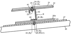
ソーラパネル用支持ビームAの取り付けに際しては、図3に拡大して示すように、屋根側支持片14、15が屋根の傾斜面下方に向くように屋根瓦20の高い部分20a上に載置する。これらの屋根側支持片14、15にはこれらの長手方向に複数個の前記ネジ孔17、18が設けられており、これらのネジ孔17、18には屋根瓦20に形成された取り付け孔32およびその屋根瓦20を支持する野地板27に形成された取り付け孔33を通して、野地板27の下面側から挿入されたボルト28の先端部がねじ込まれている。
When the solar panel support beam A is attached, as shown in an enlarged view in FIG. 3, the solar panel support beam A is placed on the
前記野地板27は垂木26上に木ネジ等により固定され、垂木26はこれに直交する方向に配置された母屋29に支持され、この母屋29はつか30を介して梁31上に支承されている。なお、図示しないが、屋根瓦20の取り付け孔24とこれに挿通されたボルト28の軸部との隙間には、シール処理(図示しない)が施されている。
The
このようにして、屋根瓦20上に取り付けられた複数本のソーラパネル用支持ビームAは、これのソーラパネル支持片11上にソーラパネル21を、支持枠22を介して支承することができる。この場合において、屋根側支持片14、15が共に屋根の傾斜面下方に向けて延設された状態にて屋根瓦20上面に載置されているため、降雨時にソーラパネル21を伝わって屋根瓦20上に落下する雨水や、屋根瓦20上面に傾斜面下方に流下する雨水は、屋根側支持片14、15上のいずれにも滞留することなく流下していく。従って、雨水の滞留およびこの雨水の滞留による屋根側支持片14、15の腐食を未然に回避することができる。
In this manner, the plurality of solar panel support beams A attached on the
図4は、本考案の他の実施形態による金属製支持ビームを示す斜視図、図5は、この金属製支持ビームを屋根瓦20上面に取り付けた状態を示す要部の断面図である。この実施形態でも、金属製支持ビームがソーラパネル用支持ビームである場合を例にして説明する。この実施形態のソーラパネル用支持ビームBは、ソーラパネル支持片41と、垂直短片42(リップ)と、垂直長片43と、屋根側支持片44と、を備える。これらのうちソーラオパネル支持片41は所定のサイズおよび厚みを有し、ソーラパネルの下面を支承する平坦面を持つ。垂直短片42および垂直長片43はソーラパネル支持片41の幅方向の両端からそれぞれ一体に垂下延設されている。屋根側支持片44は、ソーラパネル支持片41に対して平行となるように、垂直長片43の下端に連続している。
FIG. 4 is a perspective view showing a metal support beam according to another embodiment of the present invention, and FIG. 5 is a cross-sectional view of a main part showing a state in which the metal support beam is attached to the upper surface of the
さらに、ソーラパネル支持片41にはこれの長手方向に、ソーラパネルをボルト等により取り付けるための複数個の取り付け孔45が形成され、屋根側支持片44には、ソーラパネル支持ビームBの全体を、ネジ部材を用いて屋根瓦20に取り付けるための取り付け孔(としてのネジ孔)46が形成されている。
Further, the solar
ここで、ソーラパネル支持ビームBは長尺の鋼板を折曲加工することによって得られる。そして、この鋼板の厚みを例えば2.3ミリまたは3.2ミリとした場合には、ソーラパネル支持片41の幅は、例えば50mミリ、55ミリ、75ミリのいずれかとされ、垂下片42の長さは25ミリ〜50ミリのいずれかとされ、垂下片43の長さ(高さ)は100ミリまたは125ミリとされ、屋根側支持片44の幅はソーラパネル支持片41に略等しい幅とされている。
Here, the solar panel support beam B is obtained by bending a long steel plate. When the thickness of the steel sheet is set to 2.3 mm or 3.2 mm, for example, the width of the solar
かかる構成のソーラパネル支持ビームBを用いて屋根の傾斜面上にソーラパネル21を取り付けた状態は、図5に示す通りである。ソーラパネル21は、矩形の支持枠22上に複数枚が1ユニットとして、複数ユニット分が並設されている。これらの支持枠22の下面には、縦方向(屋根が傾斜する方向)の複数箇所に、ソーラパネル用支持ビームBが水平方向(前記縦方向に直行する方向)に取り付けられている。
The state in which the
このソーラパネル用支持ビームBの支持枠22に対するソーラパネル21の取り付けは、ソーラパネル支持片41に形成された取り付け孔45および支持枠22に形成された取り付け孔24にボルト22を下方から通し、その先端にナット25を締め付けることにより、簡単かつ迅速に行える。なお、取り付け孔45がネジ孔である場合には、支持枠22に形成された前記取り付け孔24を通してボルトをそのネジ孔にねじ込むことができる。今場合には、ナットを用いることなくソーラパネル用ビームBの支持枠22に対する取り付けが更に簡単に行える。
The
ソーラパネル用支持ビームBの取り付けに際しては、屋根側支持片44が屋根の傾斜面下方に向くように屋根瓦20の高い部分20a上に載置する。この屋根側支持片44にはこれの長手方向に複数個の前記ネジ孔46が設けられている。そこで、このネジ孔46には、屋根瓦20に形成された取り付け孔32およびこの屋根瓦20を支持する野地板27に形成された取り付け孔33を通して、野地板27の下面側からボルト28を挿入し、その先端部をねじ込む。
When mounting the solar panel support beam B, the solar
前記野地板27は垂木26上にネジ等により固定され、垂木は、これに直交する方向に配置された母屋29に支持され、この母屋29はつか30を介して梁31上に支承されている。なお、図示しないが、屋根瓦20の取り付け孔24とこれに挿通されたボルト28の軸部との隙間にはシール処理が施されている。
The
屋根瓦20上に取り付けられた複数本のソーラパネル用支持ビームBは、これのソーラパネル支持片11上にソーラパネル21を、支持枠22を介して支承することができる。この場合において、屋根側支持片44が屋根の傾斜面下方に向けて延設された状態にて屋根瓦20上面に載置されているため、降雨時にソーラパネル21を伝わって屋根瓦20上面に落下する雨水や、屋根瓦20上面に傾斜下方に流下する雨水は、屋根側支持片44上のいずれにも滞留することなく流下していく。従って、雨水の滞留およびこの雨水の滞留による屋根側支持片44の腐食を未然に回避することができる。
The plurality of solar panel support beams B mounted on the
以上のように、本考案の一実施形態による金属製支持ビームAは、建築部材や構築部材等21の下面を支持する平坦な上部支持片11と、この上部支持片11の両端に、この上部支持片11に対し直交する方向に連設された同一長の垂直片12、13と、これらの垂直片12、13の下端に、上部支持片11に対し平行で、これらの垂直片12、13に対しそれぞれ同一方向に連続する下部支持片14、15と、を備えて、これらの下部支持片14、15を建築部材や構築部材の傾斜面下方に向くように支持させるような構成としている。
As described above, the metal support beam A according to the embodiment of the present invention includes the flat
また、本考案の他の実施形態による金属製支持ビームBは、建築部材や構築部材の面を支持する平坦な上部支持片41と、この上部支持片41の一端に、この上部支持片41に対し直交する方向に連設された垂直短片42と、前記上部支持片41の他端に、この上部支持片41に対し直交する方向に連設された垂直長片43と、この垂直長片43の下端に上部支持片41に対して平行で、かつこの十部支持片41と同一方向に連続する下部支持片44と、を備えて、この下部支持片44を建築部材や構築部材の傾斜方向に延設されるように支持させた構成としている。
In addition, the metal support beam B according to another embodiment of the present invention includes a flat
従って、金属製支持ビームA、Bは、例えば家屋等の屋根の傾斜面上にソーラパネル21を支持した際に、下部支持片14、15,44が屋根瓦20上の雨水の流下を妨げることがなく、また、下部支持片14、15、44が雨水の溜り場所を作らないので、雨水の滞留による金属製支持ビームA、Bの腐食や錆発生による外観の劣化を未然に回避することができる。また7リップが切除されている分、金属製支持ビームAであるリップ溝型鋼の重量の軽減と省資源に寄与できるものとなる。
Therefore, the metal support beams A and B prevent the
なお、前記実施の形態では、金属製支持ビームがソーラパネル支持ビームAである場合を説明したが、建築部材である胴縁や屋根梁、或いは間柱、さらには土木や機械、設備などの分野における構築物などの支持ビームとしても広く利用可能である。 In the above-described embodiment, the case where the metal support beam is the solar panel support beam A has been described. However, in the field of a building member such as a trunk edge, a roof beam, or a stud, and also civil engineering, machinery, and equipment. It can be widely used as a support beam for structures and the like.
また、ソーラパネル支持ビームAは、柱に溶接されたL字状アングルピースの水平片に対して、垂直長片17をボルト止めする形式の取付構造(図示しない)にあっても、雨水滞留の防止を有効に実現できる。
Even if the solar panel support beam A has an attachment structure (not shown) in which the vertical
本考案にかかるソーラパネル用支持ビームは屋根の傾斜面上でソーラパネルを支承する状態においても、鋼材からなるビーム内に雨水や塵埃などが滞留するなどして、その鋼材自体の腐食およびこの腐食による耐久性の劣化を未然に回避できるという効果を有し、家屋等の屋根の上でソーラパネルを支持するソーラパネル支持ビーム等に有用である。 Even when the solar panel support beam according to the present invention supports the solar panel on the inclined surface of the roof, rainwater and dust stay in the beam made of steel, causing corrosion of the steel itself and this corrosion. It is effective for a solar panel support beam for supporting a solar panel on a roof such as a house.
11…ソーラパネル支持片(上部支持片)、12,13…垂直片、14,15…屋根側支持片(下部支持片)、16…取り付け孔、17,18…ネジ孔(取り付け孔)、20…屋根瓦、21…ソーラパネル、22…支持枠、23…ボルト、 24…取り付け孔、25…ナット、26…垂木、27…野地板、28…ボルト、 29…母屋、30…つか、31…梁、41…ソーラパネル支持片、42…垂直短片、43…垂直長片、44…屋根側支持片、45…取り付け孔、46…ネジ孔、 A,B…ソーラパネル支持ビーム(金属製支持ビーム)
DESCRIPTION OF
Claims (2)
建築部材や構築部材の下面を支持する平坦な上部支持片と、
この上部支持片の両端に、この上部支持片に対し直交する方向に連設された同一長の垂直片と、
これらの垂直片の下端に、前記上部支持片に対し平行で、これらの垂直片に対しそれぞれ同一方向に連続する下部支持片と、を備え、
これらの下部支持片が前記建築部材や構築部材等の傾斜面下方に向くように支持されることを特徴とする建築用または構築用の金属製支持ビーム。 A metal support beam for construction or construction,
A flat upper support piece that supports the lower surface of the building member or building member;
A vertical piece of the same length connected to both ends of the upper support piece in a direction orthogonal to the upper support piece;
A lower support piece, which is parallel to the upper support piece and continuous in the same direction with respect to the vertical piece at the lower ends of the vertical pieces,
A metal support beam for construction or construction, characterized in that these lower support pieces are supported so as to face downward of the inclined surfaces of the building members and construction members.
建築部材や構築部材の下面を支持する平坦な上部支持片と、
この上部支持片の一端にこの上部支持片に対し直交する方向に連設された垂直短片と、
前記上部支持片の他端に、この上部支持片に対し直交する方向に連設された前記垂直短片より長い垂直長片と、
この垂直長片の下端に前記上部支持片に対して平行で、かつこの上部支持片と同一方向に連続する下部支持片と、を備え、
この下部支持片が前記建築部材や構築部材等の傾斜面下方に向くように支持されることを特徴とするソーラパネル支持ビーム。 A metal support beam for construction or construction,
A flat upper support piece that supports the lower surface of the building member or building member;
A vertical short piece connected to one end of the upper support piece in a direction perpendicular to the upper support piece;
A vertical long piece longer than the vertical short piece provided in a direction orthogonal to the upper support piece at the other end of the upper support piece;
A lower support piece parallel to the upper support piece at the lower end of the vertical long piece and continuous in the same direction as the upper support piece,
A solar panel support beam, characterized in that the lower support piece is supported so as to face downward of an inclined surface of the building member or building member.
Priority Applications (1)
| Application Number | Priority Date | Filing Date | Title |
|---|---|---|---|
| JP2010000967U JP3159980U (en) | 2010-02-17 | 2010-02-17 | Metal support beam |
Applications Claiming Priority (1)
| Application Number | Priority Date | Filing Date | Title |
|---|---|---|---|
| JP2010000967U JP3159980U (en) | 2010-02-17 | 2010-02-17 | Metal support beam |
Publications (2)
| Publication Number | Publication Date |
|---|---|
| JP3159980U true JP3159980U (en) | 2010-06-10 |
| JP3159980U7 JP3159980U7 (en) | 2011-06-30 |
Family
ID=54863201
Family Applications (1)
| Application Number | Title | Priority Date | Filing Date |
|---|---|---|---|
| JP2010000967U Expired - Lifetime JP3159980U (en) | 2010-02-17 | 2010-02-17 | Metal support beam |
Country Status (1)
| Country | Link |
|---|---|
| JP (1) | JP3159980U (en) |
Cited By (3)
| Publication number | Priority date | Publication date | Assignee | Title |
|---|---|---|---|---|
| WO2012114550A1 (en) * | 2011-02-23 | 2012-08-30 | 日新製鋼株式会社 | Steel single-lip channel bar |
| JP2012172455A (en) * | 2011-02-23 | 2012-09-10 | Nisshin Steel Co Ltd | Lip channel steel |
| JP2019078095A (en) * | 2017-10-25 | 2019-05-23 | 三菱電機株式会社 | Metal fitting and solar cell system |
-
2010
- 2010-02-17 JP JP2010000967U patent/JP3159980U/en not_active Expired - Lifetime
Cited By (4)
| Publication number | Priority date | Publication date | Assignee | Title |
|---|---|---|---|---|
| WO2012114550A1 (en) * | 2011-02-23 | 2012-08-30 | 日新製鋼株式会社 | Steel single-lip channel bar |
| JP2012172455A (en) * | 2011-02-23 | 2012-09-10 | Nisshin Steel Co Ltd | Lip channel steel |
| CN103328742A (en) * | 2011-02-23 | 2013-09-25 | 日新制钢株式会社 | Steel single-lip channel bar |
| JP2019078095A (en) * | 2017-10-25 | 2019-05-23 | 三菱電機株式会社 | Metal fitting and solar cell system |
Similar Documents
| Publication | Publication Date | Title |
|---|---|---|
| JP5365937B2 (en) | Solar panel mounting device | |
| AU2011245978B2 (en) | Sheet body supporting frame and photovoltaic power generation device | |
| JP3159980U (en) | Metal support beam | |
| JP3159980U7 (en) | ||
| JP2014148822A (en) | Installation device of solar battery array to folded-plate roof | |
| US20140318046A1 (en) | Purlin construction for roof structures | |
| JP2014025288A (en) | Solar car port | |
| JP2005315018A (en) | Rack mounting structure for placing article on roof, rack mounting metal piece and rack mounting method | |
| JP3202583U (en) | Support structure for photovoltaic panels | |
| JP2002021266A (en) | Flat roof structure | |
| FI20196053A1 (en) | Arrangement for fastening solar panels | |
| US9267712B1 (en) | Strap mount for solar panels | |
| JP5805012B2 (en) | Solar cell module fixing device | |
| JP3158870U (en) | Metal support beam | |
| JP5430544B2 (en) | Auxiliary rafter fixing bracket and equipment fixing device | |
| JP2018003244A (en) | Roof panel, and roof structure of building | |
| JP6869789B2 (en) | Exterior wall repair structure | |
| JP2009133093A (en) | Roof reinforcing method, roof reinforcing structure, roof reinforcing member, and installation fixing bracket | |
| US10436479B2 (en) | Fixture for solar cell module | |
| JP5859098B1 (en) | Roof mounting fixture | |
| CN203097129U (en) | Windproof clamp for light steel building roof system | |
| JP2014148817A (en) | Simple structure | |
| JP5216683B2 (en) | Support structure for folded plate roof | |
| JP2012047007A (en) | Attachment structure of support frame and exterior structure | |
| CN210395648U (en) | Steel bar processing protection shed channel steel purline coupling mechanism |
Legal Events
| Date | Code | Title | Description |
|---|---|---|---|
| A521 | Written amendment |
Free format text: JAPANESE INTERMEDIATE CODE: A523 Effective date: 20100326 |
|
| A521 | Written amendment |
Free format text: JAPANESE INTERMEDIATE CODE: A523 Effective date: 20100325 |
|
| R150 | Certificate of patent or registration of utility model |
Ref document number: 3159980 Country of ref document: JP Free format text: JAPANESE INTERMEDIATE CODE: R150 Free format text: JAPANESE INTERMEDIATE CODE: R150 |
|
| FPAY | Renewal fee payment (event date is renewal date of database) |
Free format text: PAYMENT UNTIL: 20130519 Year of fee payment: 3 |
|
| A624 | Registrability report (other person) |
Free format text: JAPANESE INTERMEDIATE CODE: A624 Effective date: 20101110 |
|
| FPAY | Renewal fee payment (event date is renewal date of database) |
Free format text: PAYMENT UNTIL: 20130519 Year of fee payment: 3 |
|
| R231 | Written correction (descriptions, etc.) |
Free format text: JAPANESE INTERMEDIATE CODE: R231 |
|
| FPAY | Renewal fee payment (event date is renewal date of database) |
Free format text: PAYMENT UNTIL: 20130519 Year of fee payment: 3 |
|
| R157 | Certificate of patent or utility model (correction) |
Free format text: JAPANESE INTERMEDIATE CODE: R157 |
|
| FPAY | Renewal fee payment (event date is renewal date of database) |
Free format text: PAYMENT UNTIL: 20130519 Year of fee payment: 3 |
|
| R157 | Certificate of patent or utility model (correction) |
Free format text: JAPANESE INTERMEDIATE CODE: R157 |
|
| FPAY | Renewal fee payment (event date is renewal date of database) |
Free format text: PAYMENT UNTIL: 20130519 Year of fee payment: 3 |
|
| FPAY | Renewal fee payment (event date is renewal date of database) |
Free format text: PAYMENT UNTIL: 20130519 Year of fee payment: 3 |
|
| FPAY | Renewal fee payment (event date is renewal date of database) |
Free format text: PAYMENT UNTIL: 20160519 Year of fee payment: 6 |
|
| R250 | Receipt of annual fees |
Free format text: JAPANESE INTERMEDIATE CODE: R250 |
|
| R250 | Receipt of annual fees |
Free format text: JAPANESE INTERMEDIATE CODE: R250 |
|
| R250 | Receipt of annual fees |
Free format text: JAPANESE INTERMEDIATE CODE: R250 |
|
| R250 | Receipt of annual fees |
Free format text: JAPANESE INTERMEDIATE CODE: R250 |
|
| EXPY | Cancellation because of completion of term |