JP3156789U - Electronic device operating device rotating structure and operating device rotating structure - Google Patents
Electronic device operating device rotating structure and operating device rotating structure Download PDFInfo
- Publication number
- JP3156789U JP3156789U JP2009006875U JP2009006875U JP3156789U JP 3156789 U JP3156789 U JP 3156789U JP 2009006875 U JP2009006875 U JP 2009006875U JP 2009006875 U JP2009006875 U JP 2009006875U JP 3156789 U JP3156789 U JP 3156789U
- Authority
- JP
- Japan
- Prior art keywords
- fixed
- base
- rotating
- electronic device
- operating device
- Prior art date
- Legal status (The legal status is an assumption and is not a legal conclusion. Google has not performed a legal analysis and makes no representation as to the accuracy of the status listed.)
- Expired - Fee Related
Links
- 230000002093 peripheral effect Effects 0.000 claims abstract description 23
- 230000004807 localization Effects 0.000 claims description 28
- 238000010586 diagram Methods 0.000 description 3
- 238000000034 method Methods 0.000 description 2
- 230000003247 decreasing effect Effects 0.000 description 1
- 230000000994 depressogenic effect Effects 0.000 description 1
- 230000000694 effects Effects 0.000 description 1
- 230000000007 visual effect Effects 0.000 description 1
Images


Classifications
-
- G—PHYSICS
- G06—COMPUTING; CALCULATING OR COUNTING
- G06F—ELECTRIC DIGITAL DATA PROCESSING
- G06F1/00—Details not covered by groups G06F3/00 - G06F13/00 and G06F21/00
- G06F1/16—Constructional details or arrangements
- G06F1/1613—Constructional details or arrangements for portable computers
- G06F1/1615—Constructional details or arrangements for portable computers with several enclosures having relative motions, each enclosure supporting at least one I/O or computing function
-
- F—MECHANICAL ENGINEERING; LIGHTING; HEATING; WEAPONS; BLASTING
- F16—ENGINEERING ELEMENTS AND UNITS; GENERAL MEASURES FOR PRODUCING AND MAINTAINING EFFECTIVE FUNCTIONING OF MACHINES OR INSTALLATIONS; THERMAL INSULATION IN GENERAL
- F16M—FRAMES, CASINGS OR BEDS OF ENGINES, MACHINES OR APPARATUS, NOT SPECIFIC TO ENGINES, MACHINES OR APPARATUS PROVIDED FOR ELSEWHERE; STANDS; SUPPORTS
- F16M11/00—Stands or trestles as supports for apparatus or articles placed thereon ; Stands for scientific apparatus such as gravitational force meters
- F16M11/02—Heads
- F16M11/04—Means for attachment of apparatus; Means allowing adjustment of the apparatus relatively to the stand
- F16M11/06—Means for attachment of apparatus; Means allowing adjustment of the apparatus relatively to the stand allowing pivoting
-
- G—PHYSICS
- G06—COMPUTING; CALCULATING OR COUNTING
- G06F—ELECTRIC DIGITAL DATA PROCESSING
- G06F1/00—Details not covered by groups G06F3/00 - G06F13/00 and G06F21/00
- G06F1/16—Constructional details or arrangements
- G06F1/1601—Constructional details related to the housing of computer displays, e.g. of CRT monitors, of flat displays
- G06F1/1605—Multimedia displays, e.g. with integrated or attached speakers, cameras, microphones
-
- G—PHYSICS
- G06—COMPUTING; CALCULATING OR COUNTING
- G06F—ELECTRIC DIGITAL DATA PROCESSING
- G06F1/00—Details not covered by groups G06F3/00 - G06F13/00 and G06F21/00
- G06F1/16—Constructional details or arrangements
- G06F1/1613—Constructional details or arrangements for portable computers
- G06F1/1633—Constructional details or arrangements of portable computers not specific to the type of enclosures covered by groups G06F1/1615 - G06F1/1626
- G06F1/1675—Miscellaneous details related to the relative movement between the different enclosures or enclosure parts
- G06F1/1681—Details related solely to hinges
-
- F—MECHANICAL ENGINEERING; LIGHTING; HEATING; WEAPONS; BLASTING
- F16—ENGINEERING ELEMENTS AND UNITS; GENERAL MEASURES FOR PRODUCING AND MAINTAINING EFFECTIVE FUNCTIONING OF MACHINES OR INSTALLATIONS; THERMAL INSULATION IN GENERAL
- F16M—FRAMES, CASINGS OR BEDS OF ENGINES, MACHINES OR APPARATUS, NOT SPECIFIC TO ENGINES, MACHINES OR APPARATUS PROVIDED FOR ELSEWHERE; STANDS; SUPPORTS
- F16M2200/00—Details of stands or supports
- F16M2200/02—Locking means
- F16M2200/021—Locking means for rotational movement
- F16M2200/024—Locking means for rotational movement by positive interaction, e.g. male-female connections
-
- G—PHYSICS
- G05—CONTROLLING; REGULATING
- G05G—CONTROL DEVICES OR SYSTEMS INSOFAR AS CHARACTERISED BY MECHANICAL FEATURES ONLY
- G05G9/00—Manually-actuated control mechanisms provided with one single controlling member co-operating with two or more controlled members, e.g. selectively, simultaneously
- G05G9/02—Manually-actuated control mechanisms provided with one single controlling member co-operating with two or more controlled members, e.g. selectively, simultaneously the controlling member being movable in different independent ways, movement in each individual way actuating one controlled member only
- G05G9/04—Manually-actuated control mechanisms provided with one single controlling member co-operating with two or more controlled members, e.g. selectively, simultaneously the controlling member being movable in different independent ways, movement in each individual way actuating one controlled member only in which movement in two or more ways can occur simultaneously
- G05G9/047—Manually-actuated control mechanisms provided with one single controlling member co-operating with two or more controlled members, e.g. selectively, simultaneously the controlling member being movable in different independent ways, movement in each individual way actuating one controlled member only in which movement in two or more ways can occur simultaneously the controlling member being movable by hand about orthogonal axes, e.g. joysticks
- G05G2009/04703—Mounting of controlling member
Landscapes
- Engineering & Computer Science (AREA)
- General Engineering & Computer Science (AREA)
- Theoretical Computer Science (AREA)
- Computer Hardware Design (AREA)
- Physics & Mathematics (AREA)
- Human Computer Interaction (AREA)
- General Physics & Mathematics (AREA)
- Multimedia (AREA)
- Mechanical Engineering (AREA)
- Mathematical Physics (AREA)
- Pivots And Pivotal Connections (AREA)
Abstract
【課題】正回転と逆回転の回転角度を拡大し、電子装置の多様な使用を可能とする電子装置の操作装置の回転構造及び操作装置の回転構造を備える電子装置を提供する。【解決手段】内周面に位置限定凹溝111を備える固定台体10と内周面に削平面421を設けた回転スリーブ42を回転台40を有する。回転スリーブ端面に定位凸ブロック422を設け、固定台体と回転台とを嵌合させ、固定台体内に内、外位置限定ブロック22、21を設けた位置限定環状体20を収容して配置し、位置限定凸ブロック33を備えるピボット30をこれらに貫通・配置する。【選択図】図3A rotating structure of an operating device for an electronic device and an electronic device provided with the rotating structure of the operating device that enable various uses of the electronic device by enlarging the rotation angle between forward rotation and reverse rotation. A rotary table 40 includes a fixed base 10 having a position-limited groove 111 on an inner peripheral surface and a rotary sleeve 42 provided with a grinding plane 421 on the inner peripheral surface. A stereotaxic block 422 is provided on the end surface of the rotary sleeve, the fixed base and the rotary base are fitted, and the position limited annular body 20 provided with the inner and outer position limited blocks 22 and 21 is accommodated in the fixed base. The pivot 30 provided with the position-limiting convex block 33 is penetrated and arranged in these. [Selection] Figure 3
Description
本考案は、電子装置の操作装置の回転構造及び操作装置の回転構造を備える電子装置に関し、特に各種電子装置に応用し、電子装置を回転可能とする構造である電子装置の操作装置の回転構造及び操作装置の回転構造を備える電子装置に関するものである。 The present invention relates to a rotating structure of an operating device for an electronic device and an electronic device provided with a rotating structure for an operating device, and more particularly to a rotating structure of an operating device for an electronic device that is applied to various electronic devices and is capable of rotating the electronic device. The present invention also relates to an electronic device having a rotating structure of an operating device.
カメラのレンズ、ゲーム機の操作スティックなど、現在使用されている電子関連製品の多くは、2個の部品間に操作装置の回転構造を備える。
これにより、該2個の部品は相対的に回転し、その相対位置を変換し、それぞれに異なる方式によって、使用の効果を達成する。
Many electronic-related products currently used, such as camera lenses and game machine operation sticks, have a rotating structure of an operation device between two parts.
As a result, the two parts rotate relative to each other and change their relative positions, thereby achieving the use effect by different methods.
図16に示すように、従来の電子装置の操作装置の回転構造は、第一ケース70と第二ケース80からなる。
第一、第二ケース70、80は、中空の殻体で、内部には、相互に電気的に接続する電子部品をそれぞれ設置し、これにより該電子装置の作動に必要な機能を提供する。
第一ケース70の端部には、穿孔を貫通して設け、第一ケース70内部の、穿孔に相対する側には、定位弾力片71と定位片72を設置する。
As shown in FIG. 16, the conventional rotating structure of the electronic device operating device includes a
The first and
A perforation is provided through the end of the
第二ケース80端部には、軸筒81を突出して設ける。
軸筒81は、第一ケース70の穿孔に通して配置し、その内部へ突出する。
軸筒81中央には、軸孔811を軸方向に貫通して設ける。
軸孔811と第二ケース80の内部は通じ、これにより第一、第二ケース70、80内の電子部品は電線を通して設置し、接続することができる。
軸筒81の自由端において、環状の定位盤82を突出して設置する。
定位盤82の端面上には、間隔を開けて径方向に複数の定位リブ821を環状に設置し、周縁上には、径方向に突出して定位ブロック822を設置する。
A shaft cylinder 81 is provided projecting from the end of the second case 80.
The shaft cylinder 81 is disposed through the perforation of the
A
The
At the free end of the shaft cylinder 81, an annular positioning plate 82 is protruded and installed.
A plurality of
図17に示すように、定位片72と定位ブロック822は、相互に対応した設計である。
これにより、ストッパー機能を備え、第一、第二ケース70、80が相対して過度に回転しないよう防止する。
しかし、定位片72は厚みを備えるため、定位盤82の定位ブロック822が、定位片72の片側から逆時計回りに定位片72の反対側まで回転すると、同一位置へと戻ることができず、もとの位置との間にはθ角のギャップが生じる。
このような設計では、定位片72と定位ブロック822との間には、ストッパー機能があったとしても、360度回転した後、もとの位置に完全に戻ることはできず、逆方向に回転しなければ、もとの位置に戻ることはできない。
つまり、その回転角度には限界があり、それが使用上の不便を招いている。
本考案は、従来の電子装置の操作装置の回転構造の上記した欠点に鑑みてなされたものである。
As shown in FIG. 17, the
Thereby, it has a stopper function and prevents the first and
However, since the
In such a design, even if there is a stopper function between the
That is, the rotation angle has a limit, which causes inconvenience in use.
The present invention has been made in view of the above-described drawbacks of the conventional rotating structure of the operating device of an electronic device.
本考案が解決しようとする課題は、正回転と逆回転の回転角度を拡大し、電子装置の多様な使用を可能とする電子装置の操作装置の回転構造及び操作装置の回転構造を備える電子装置を提供することである。 The problem to be solved by the present invention is to increase the rotation angle between forward rotation and reverse rotation, and to enable various uses of the electronic device, the rotating structure of the operating device of the electronic device and the electronic device including the rotating structure of the operating device Is to provide.
上記課題を解決するため、本考案は下記の電子装置の操作装置の回転構造及び操作装置の回転構造を備える電子装置を提供する。
電子装置の操作装置の回転構造は、中空で、かつ内壁面は、径方向に窪んで、位置限定凹溝を形成する固定台体、該固定台体中に通して設置する位置限定環状体、該固定台体と該位置限定環状体を貫通するピボット、該ピボット外に嵌めて固定し、しかも該固定台体と隣接する回転台体、該ピボットの自由端外に嵌めて固定する固定部品からなり、
該位置限定環状体の外周壁面には、径方向に突出して、外位置限定ブロックを形成し、該位置限定環状体の外位置限定ブロックは、該固定台体の位置限定凹溝中に位置し、
該位置限定環状体の内周壁面には、径方向に突出して、内位置限定ブロックを形成し、
該ピボットは、棒体、冠部、位置限定凸ブロックを備え、
該冠部は、該棒体の自由端周囲を取り囲んで形成し、
該位置限定凸ブロックは、径方向に延伸して、該棒体の外壁面に形成し、該ピボットの該位置限定凸ブロックは、該位置限定環状体の内壁面位置に相対し、
使用時には、電子装置の回転ケースと該回転台体とを相互に固定し、さらに、電子装置の固定ケースと該固定台体とは相互に固定する。
In order to solve the above-described problems, the present invention provides the following electronic device operating device rotating structure and operating device rotating structure.
The rotating structure of the operating device of the electronic device is hollow, and the inner wall surface is recessed in the radial direction to form a position-limited concave groove, a position-limited annular body that is installed through the fixed base, A pivot that passes through the fixed base and the position-limited annular body, and is fitted and fixed outside the pivot, and a rotating base adjacent to the fixed base, and a fixed part that is fitted and fixed outside the free end of the pivot. Become
On the outer peripheral wall surface of the position limited annular body, an outer position limited block is formed projecting in the radial direction, and the outer position limited block of the position limited annular body is located in the position limited concave groove of the fixed base body. ,
On the inner peripheral wall surface of the position-limited annular body, projecting in the radial direction to form an inner position-limited block,
The pivot includes a rod, a crown, and a position-limited convex block,
The crown is formed around the free end of the rod;
The position limited convex block extends in the radial direction and is formed on the outer wall surface of the rod body, and the position limited convex block of the pivot is opposed to the inner wall surface position of the position limited annular body;
In use, the rotating case of the electronic device and the rotating base are fixed to each other, and the fixing case of the electronic device and the fixing base are fixed to each other.
本考案電子装置の操作装置の回転構造は、ピボットの位置限定凸ブロック、位置限定環状体の内、外位置限定ブロック、固定台体の位置限定凹溝を設けたことにより、回転台体とピボットは、2段階式の回転を達成し、これらを合わせて回転可能な角度を拡大し、位置限定凸ブロック、内、外位置限定ブロック、位置限定凹溝のサイズの調整を対応させ、360度から700度まで回転可能とすることができる。 The rotation structure of the operation device of the electronic device according to the present invention is such that the position limited convex block of the pivot, the position limited annular body, the outer position limited block, and the position limited concave groove of the fixed base are provided. Achieves a two-stage rotation, expands the angle that can be rotated by combining these, and supports the adjustment of the size of the position limited convex block, inner and outer position limited block, position limited concave groove from 360 degrees It can be rotated up to 700 degrees.
以下に図面を参照しながら本考案を実施するための最良の形態について詳細に説明する。 The best mode for carrying out the present invention will be described below in detail with reference to the drawings.
図1、2、3に示すように、本考案第一実施例は、固定板体11と固定スリーブ12を備える固定台体10、該固定台体10中に通して設置して該固定スリーブ12の接続端に接触する位置限定環状体20、該固定台体10と該位置限定環状体20中に通して設置するピボット30、該ピボット30外に嵌めて固定する回転台体40、該ピボット30の棒体31外に嵌めて設置する弾性部品、該ピボット30の棒体31の自由端に嵌めて、固定する固定部品60からなる。
As shown in FIGS. 1, 2, and 3, the first embodiment of the present invention is a
図3、4、5に示すように、該固定板体11は中空で、その内壁面は、径方向に窪んで、位置限定凹溝111を形成する。
As shown in FIGS. 3, 4, and 5, the fixed plate body 11 is hollow, and its inner wall surface is recessed in the radial direction to form a position-restricted
該固定スリーブ12は、該固定板体11の片側面上に軸方向に延長して形成する。
該固定スリーブ12の内径は、固定板体11の内径より小さい。
該固定スリーブ12の自由端には、定位部品を形成する。
該定位部品は、相対する2個の定位凹溝121とする。
The
The inner diameter of the
A stereotactic part is formed at the free end of the fixed
The localization parts are two
図3、4、5、6に示すように、該位置限定環状体20の外周壁面は、径方向に突出して、外位置限定ブロック21を形成する。
該外位置限定ブロック21は、固定台体10の位置限定凹溝111中に相対して位置する。
As shown in FIGS. 3, 4, 5, and 6, the outer peripheral wall surface of the position limited
The outer
該位置限定環状体20の内周壁面は、径方向に突出して、内位置限定ブロック22を形成する。
該内位置限定ブロック22は、該外位置限定ブロック21と、180度相対して位置する。
The inner peripheral wall surface of the position limited
The inner
図3、4に示すように、該ピボット30は、棒体31、冠部32、位置限定凸ブロック33を備える。
該棒体31は、自由端と接続端を備える。
該棒体31の外周壁面上には、相対して削りだした平面311を形成する。
該棒体31の外周壁面の接続端に近接する位置の周囲には、ネジヤマ312を形成する。
As shown in FIGS. 3 and 4, the pivot 30 includes a
The
On the outer peripheral wall surface of the
A
該冠部32は、棒体31の自由端周囲を取り囲んで形成し、該固定台体10の固定板体11中に通して配置する。
該位置限定凸ブロック33は、径方向に突出して、棒体31の外周壁面の自由端に近接する位置に形成する。
該位置限定凸ブロック33は、位置限定環状体20の内周壁面位置に相対して、位置限定環状体20の内位置限定ブロック22に相対する。
The
The position-limited
The position-limiting
図3、4、5に示すように、回転台体40は、中空の回転板体41、回転スリーブ42を備える。回転板体41の片側面上に軸方向に延長して形成する。
該回転スリーブ42の内径は、回転板体41の内径より小さい。
該回転スリーブ42の内周壁面には、相対して2つの削りだし平面421を形成する。
As shown in FIGS. 3, 4, and 5, the
The inner diameter of the
Two shaving
該回転台体40の削りだし平面421と、該棒体31の削りだし平面311は、相互に密着し、これにより、該回転台体40と該ピボット30は固定される。
The cutting
該回転スリーブ42の自由端には、該固定スリーブ12の定位部品である定位凹溝121に相対する定位部品を形成し、該回転スリーブ42の定位部品は、相対する2個の定位凸ブロック422とする。
該回転スリーブ42の定位部品と、該固定台体10の定位部品とは相互に嵌合し、これにより、該固定台体10と該回転台体40とは、相対して回転動することができなくなる。
At the free end of the
The localization component of the
図3、6に示すように、バネ50などからなる該弾性部品は、回転台体40を押圧し、これにより回転台体40の定位部品と固定台体10の定位部品とは緊密に嵌合する。
該バネ50は、回転台体40中に通して設置し、該バネ50の一端は、回転スリーブ42の接続端に接する。
As shown in FIGS. 3 and 6, the elastic part composed of the
The
図3、6に示すように、ナットなどからなる該固定部品60は、該ピボットの棒体31のネジヤマ312に螺合して固定する。
As shown in FIGS. 3 and 6, the fixing component 60 made of a nut or the like is screwed and fixed to the screw yama 312 of the
図3、4、7、8、9に示すように、該回転台体40が該固定台体10に相対して回転する時、該回転台体40は、ピボット30を連動して一緒に回転させる。
この時、該ピボット30の位置限定凸ブロック33は、該ピボットの回転に伴って位置限定環状体20の内周壁面に沿って摺動する。
3, 4, 7, 8, and 9, when the
At this time, the position limiting
該位置限定凸ブロック33が、位置限定環状体20の内位置限定ブロック22を押すと、回転台体40に連動して該位置限定凸ブロック33によって押圧される内位置限定ブロック22を介して該ピボット30は、位置限定環状体20を回転させる。
When the position limited
この時、該位置限定環状体20の外位置限定ブロック21は、固定台体10の位置限定凹溝111の端部に達してそれを押すまで、固定台体10の位置限定凹溝111中においてその内周面に沿って摺動する。
こうして、該位置限定環状体20を停止させ、これにより、回転ケースはそれ以上回転することができなくなる。
At this time, the outer
Thus, the position-limited
以上の動作によって、本考案は、第一段階はピボット30の回転動、及び第二段階として、ピボット20が位置限定環状体20を押す回転動の二段階式の回転動を達成することにより、その回転動の範囲を増大することができる。
さらに、位置限定凸ブロック33、内位置限定ブロック22、外位置限定ブロック21、位置限定凹溝111のサイズを変えて、本考案は、360度から700度までの正回転と逆回転を達成することができる。
By the above operation, the present invention achieves a two-stage rotational movement in which the first stage is the rotational movement of the pivot 30 and the second stage is the rotational movement in which the
Further, by changing the size of the position limited
本考案の実施時には、電子装置の固定ケース、回転ケース中に設置する。
該固定台体10と該回転台体40は、電子装置の2個のケースとそれぞれ相互に固定する。
When implementing the present invention, the electronic device is installed in a fixed case or a rotating case of the electronic device.
The fixed
2個のケースを相対回転させようとする時には、まず、弾性部品の弾力に対抗して軸方向に対して回転ケースと固定ケースを引き離す。
これにより、該固定台体10の定位部品と、該回転台体40の定位部品とは分離する。
さらに、回転ケースを回転させ、該回転台体40を連動し、該固定台体10に対して回転させる。
When the two cases are to be rotated relative to each other, first, the rotating case and the fixed case are pulled apart in the axial direction against the elastic force of the elastic component.
Thereby, the localization component of the fixed
Further, the rotating case is rotated, the rotating
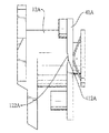
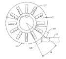
図10、11、12、13、14、15に示すように、本考案の第二実施例は、第一実施例と同様であって、以下のように、細部の構造に差異があるだけである。
ピボット30Aと固定部品60Aとの間は、リベット結合の方式で相互に固定する。
As shown in FIGS. 10, 11, 12, 13, 14, and 15, the second embodiment of the present invention is the same as the first embodiment, and only the structure of the details is different as follows. is there.
The
回転台体40Aは、中空の回転板体41Aだけを備える。
該回転板体41Aの内壁面には、相対する2個の削平面411Aを形成する。
該回転板体41Aの削平面411Aと、該ピボット30Aの削平面311Aとは、相互に密着する。
The rotary base 40A includes only a hollow
Two opposing grinding planes 411A are formed on the inner wall surface of the
The cutting plane 411A of the
該回転台体40Aの定位部品は、相対する2個の定位凹溝412Aで、該回転板体41Aの片側面に陥没して形成する。
該固定台体10Aの固定スリーブ12Aの定位部品は、相対する2個の定位凸ブロック122Aで、該定位凹溝412Aと該定位凸ブロック122Aは、対応して固定する。
The localization component of the rotary base 40A is formed by being depressed on one side of the
The localization component of the fixing
弾性部品は、弾力片50Aで、該ピボット30A外に嵌めて設置し、回転台体40Aと固定部品60Aとの間に介そうする。
The elastic part is an
実施時には、本考案を電子装置の固定ケース及び回転ケース中に設置し、固定台体10と回転台体40とは、電子装置の2個のケースとそれぞれ相互に固定する。
これにより、コンピューターゲーム用のハンドル操作(ハンドルとサポート軸棒との相対回転運動など)に応用する場合、該固定ケースと該回転ケースの相対回転位置を改変可能である。
At the time of implementation, the present invention is installed in a fixed case and a rotating case of the electronic device, and the fixed
Thereby, when applied to a handle operation for a computer game (such as a relative rotational movement between the handle and the support shaft), the relative rotational position of the fixed case and the rotational case can be modified.
また、相対回転位置の改変により、該電子装置の外形を改変可能で、これにより異なる外観と視覚的効果を表現することができ、例えば、中華民国特許第I299956号に示す構造中などに運用することができる。 Also, by changing the relative rotational position, the external shape of the electronic device can be changed, which can express different appearances and visual effects, for example, in the structure shown in the Chinese Patent No. I299956 be able to.
上記は本考案の最適実施例に過ぎず、本考案にいかなる形式上の制限をも加えるものではない。本考案は、最適実施例を上記の通り掲示したが、これは本考案を限定するものではなく、該項技術の習熟者は、本考案の精神に基づき、上記に掲示した技術内容に対して、等価応用或いは部品(構造)の転換、置換、数量の増減を行うことができ、それらはすべて、本考案の保護範囲に含むものとする。 The above are only the preferred embodiments of the present invention and do not impose any formal limitations on the present invention. Although the present invention has posted the optimum embodiment as described above, this is not intended to limit the present invention, and those skilled in the art will understand the technical contents posted above based on the spirit of the present invention. Equivalent applications or parts (structures) can be changed, replaced, and increased or decreased in quantity, all of which are included in the scope of protection of the present invention.
本考案は実用新案登録請求の要件である新規性を備え、従来の同類製品に比べ十分な進歩を有し、実用性が高く、社会のニーズに合致しており、産業上の利用価値は非常に大きい。 The present invention has a novelty that is a requirement for a utility model registration request, has sufficient progress compared to similar products of the past, has high practicality, meets social needs, and has a very high industrial utility value. Big.
10、10A 固定台体
11 固定板体
111 位置限定凹溝
12、12A 固定スリーブ
121 定位凹溝
122A 定位凸ブロック
20 位置限定環状体
21 外位置限定ブロック
22 内位置限定ブロック
30、30A ピボット
31 棒体
311、311A 削平面
312 ネジヤマ
32 冠部
33 位置限定凸ブロック
40、40A 回転台体
41、41A 回転板体
411A 削平面
412A 定位凹溝
42 回転スリーブ
421 削平面
422 定位凸ブロック
50 バネ
50A 弾力片
60 固定部品
60A 固定部品
70 第一ケース
71 定位弾力片
72 定位片
80 第二ケース
81 軸筒
811 軸孔
82 定位盤
821 定位リブ
822 定位ブロック
10, 10A Fixed base 11
Claims (13)
中空内壁面に径方向に段差を設けて位置限定凹溝を形成する固定台体、該固定台体 の中空内周壁内に配置される位置限定環状体、
該固定台体と該位置限定環状体を貫通するピボット、
上記該固定台体と該位置限定環状体を貫通するピボット一端に嵌めて固定し、かつ、固定台体と隣接する回転台体、
該固定台体に嵌めて突出するピボット端に嵌めてこれらを固定する固定部品からなり、
該位置限定環状体の外周壁面には、径方向に突出して外位置限定ブロックを形成し、該外位置限定ブロックは、該固定台体の位置限定凹溝中に位置し、
該位置限定環状体の内周壁面には、径方向に突出して内位置限定ブロックを形成し、
該ピボットは、棒体と位置限定凸ブロックを備え、該位置限定凸ブロックは、該棒体の外壁面に径方向に突出して形成して、該位置限定環状体の内周壁面位置に相対し、
該固定台体、該位置限定環状体、該回転台体を貫通して該ピボットが配置されたことを特徴とする、電子装置の操作装置の回転構造。 A rotating structure of an operating device of an electronic device,
A fixed base for forming a position-limited concave groove by providing a step in the radial direction on the hollow inner wall, a position-limited annular body disposed in the hollow inner peripheral wall of the fixed base,
A pivot passing through the fixed base and the position-limited annular body;
A fixed rotary body that is fitted and fixed to one end of a pivot that passes through the fixed base body and the position-limited annular body, and that is adjacent to the fixed base body,
It consists of a fixed part that fits into the fixed base body and fits into the protruding pivot end to fix them,
On the outer peripheral wall surface of the position limited annular body, an outer position limited block is formed by projecting in a radial direction, and the outer position limited block is located in the position limited concave groove of the fixed base body,
On the inner peripheral wall surface of the position limited annular body, an inner position limited block is formed protruding in the radial direction,
The pivot includes a rod body and a position-limiting convex block, and the position-limited convex block is formed to project radially on the outer wall surface of the rod body and is opposed to the inner peripheral wall surface position of the position-limited annular body. ,
A rotating structure of an operating device of an electronic device, wherein the pivot is disposed through the fixed base, the position-limited annular body, and the rotary base.
該位置限定環状体は、該固定板体中に通して設置したことを特徴とする、請求項1記載の電子装置の操作装置の回転構造。 The fixed base includes a hollow fixed plate body, and the position-limited concave groove of the fixed base body is formed by providing a step in the radial direction on the inner peripheral wall surface of the fixed plate body,
2. The rotating structure of the operating device for an electronic device according to claim 1, wherein the position-limited annular body is installed through the fixed plate body.
該固定スリーブは、該固定板体の該回転台体に相対する片側面上に軸方向に延伸して形成し、該固定スリーブの内径は、該固定板体の内径より小さく、
該位置限定環状体は、該固定台内で該固定スリーブを接続した端面に接して配置したことを特徴とする、請求項2記載の電子装置の操作装置の回転構造。 The fixed base includes a fixed sleeve,
The fixed sleeve is formed by extending in the axial direction on one side surface of the fixed plate body facing the rotary base, and the inner diameter of the fixed sleeve is smaller than the inner diameter of the fixed plate body,
3. The rotating structure of the operating device for an electronic device according to claim 2, wherein the position-limited annular body is disposed in contact with an end face to which the fixing sleeve is connected in the fixing base.
上記ピボットの回転台と固定部品間に弾性部品を介そうして、該回転台を固定台方向に押圧せしめることを特徴とする、請求項3記載の電子装置の操作装置の回転構造。 On the end surface of the fixed base of the fixed sleeve facing the rotary base and the rotary base surface, a stereotactic part that fits each other is formed.
4. A rotating structure of an operating device for an electronic device according to claim 3, wherein the rotating base is pressed in the direction of the fixed base through an elastic part between the rotary base of the pivot and the fixed part.
該回転台体は、中空の回転板体と回転スリーブを備え、
該回転スリーブは、該回転板体の片側面上に軸方向に延伸して形成し、該回転スリーブの内径は、該回転板体の内径より小さく、
該回転台体の定位部品は、該回転スリーブの自由端面に形成した一対の相対する定位凸ブロックであることを特徴とする、請求項4記載の電子装置の操作装置の回転構造。 The stereotaxic component of the fixed base is a pair of opposing stereotactic grooves recessed in the end face of the fixed sleeve, and the rotary base comprises a hollow rotary plate and a rotary sleeve,
The rotating sleeve is formed by extending in the axial direction on one side surface of the rotating plate, and the inner diameter of the rotating sleeve is smaller than the inner diameter of the rotating plate,
5. The rotating structure of the operating device for an electronic device according to claim 4, wherein the localization component of the rotary base is a pair of opposed localization convex blocks formed on a free end surface of the rotary sleeve.
該回転スリーブの内周壁面には、相対する2個の削平面を形成し、
該回転スリーブの削平面と、該棒体の削平面とは、相互に密着せしめるようにしたことを特徴とする、請求項5記載の電子装置の操作装置の回転構造。 On the outer peripheral wall surface of the pivot rod, an opposing grinding plane is formed,
Two opposing grinding planes are formed on the inner peripheral wall surface of the rotating sleeve,
6. The rotating structure of the operating device for an electronic device according to claim 5, wherein the cutting plane of the rotating sleeve and the cutting plane of the bar are in close contact with each other.
該固定部品はナットで、該棒体のネジヤマに螺合して固定したことを特徴とする、請求項6記載の電子装置の操作装置の回転構造。 Form a screw thread on the outer periphery of the position close to the connection end of the pivot rod,
7. The rotating structure of an operating device for an electronic device according to claim 6, wherein the fixing component is a nut, and is screwed into and fixed to a screw thread of the rod body.
該バネの一端側は、該回転スリーブの接続端に接して配置したことを特徴とする、請求項7記載の電子装置の操作装置の回転構造。 The elastic part is installed through a rotating base with a spring,
8. The rotating structure of the operating device for an electronic device according to claim 7, wherein one end side of the spring is disposed in contact with a connecting end of the rotating sleeve.
該回転台体は、回転板体を備え、該回転台体の定位部品は、該回転板体の片側面内に陥没して形成した相対する2個の定位凹溝である、ことを特徴とする、請求項4記載の電子装置の操作装置の回転構造。 The fixed parts of the fixed base are two fixed convex blocks formed on the end surface of the fixed sleeve.
The rotary base includes a rotary plate, and the localization component of the rotary base is two opposing concave grooves formed by being recessed in one side surface of the rotary plate. The rotating structure of the operating device of the electronic device according to claim 4.
該回転板体の内周壁面には、相対する2個の削平面を形成し、
該回転板体の削平面と、該ピボットの削平面とは相互に密着するようにしたことを特徴とする、請求項9記載の電子装置の操作装置の回転構造。 On the outer peripheral surface of the pivot rod, an opposing grinding plane is formed,
Two opposing grinding planes are formed on the inner peripheral wall surface of the rotating plate,
10. The rotating structure of the operating device for an electronic device according to claim 9, wherein the cutting plane of the rotating plate and the cutting plane of the pivot are in close contact with each other.
該弾力片は、該回転台体と該固定部品との間でこれらに接して配置したことを特徴とする、請求項11記載の電子装置の操作装置の回転構造。 The elastic part is an elastic piece,
12. The rotating structure of the operating device for an electronic device according to claim 11, wherein the elastic piece is disposed between and in contact with the rotary base and the fixed component.
該回転ケースは、操作装置の回転構造の回転台体と相互に固定し、
該固定ケースは、操作装置の回転構造の固定台体と相互に固定したことを特徴とする、操作装置の回転構造を備える電子装置。 An electronic device having a rotating structure of an operating device is composed of a rotating case and a fixed case,
The rotating case is mutually fixed with the rotating base of the rotating structure of the operating device,
An electronic device having a rotating structure of an operating device, wherein the fixed case is fixed to a fixed base of the rotating structure of the operating device.
Applications Claiming Priority (1)
| Application Number | Priority Date | Filing Date | Title |
|---|---|---|---|
| TW097144315A TW201020718A (en) | 2008-11-17 | 2008-11-17 | Rotation mechanism for electronic device and electronic device having rotation mechanism |
Publications (1)
| Publication Number | Publication Date |
|---|---|
| JP3156789U true JP3156789U (en) | 2010-01-21 |
Family
ID=42170869
Family Applications (1)
| Application Number | Title | Priority Date | Filing Date |
|---|---|---|---|
| JP2009006875U Expired - Fee Related JP3156789U (en) | 2008-11-17 | 2009-09-28 | Electronic device operating device rotating structure and operating device rotating structure |
Country Status (3)
| Country | Link |
|---|---|
| US (1) | US8250709B2 (en) |
| JP (1) | JP3156789U (en) |
| TW (1) | TW201020718A (en) |
Cited By (1)
| Publication number | Priority date | Publication date | Assignee | Title |
|---|---|---|---|---|
| CN111629089A (en) * | 2019-02-28 | 2020-09-04 | Oppo广东移动通信有限公司 | Electronic device |
Families Citing this family (8)
| Publication number | Priority date | Publication date | Assignee | Title |
|---|---|---|---|---|
| US8490248B2 (en) * | 2010-06-23 | 2013-07-23 | Shin Zu Shing Co., Ltd. | Hinge and an electronic device with the same |
| CN102840220A (en) * | 2011-06-21 | 2012-12-26 | 鸿富锦精密工业(深圳)有限公司 | Hinge structure |
| US20130061423A1 (en) * | 2011-09-12 | 2013-03-14 | Rebecca Elizabeth Ahern | Bushing assembly and method of assembling same |
| US9624706B2 (en) * | 2012-12-17 | 2017-04-18 | Hewlett-Packard Development Company, L.P. | Hinge assembly |
| CN107514527B (en) * | 2017-09-14 | 2023-10-13 | 深圳市固胜智能科技有限公司 | Fast-assembling base and fast-assembling device |
| CN108880827A (en) * | 2018-07-05 | 2018-11-23 | 安徽云图信息技术有限公司 | A kind of prior-warning device of network security |
| CN209435283U (en) * | 2019-03-29 | 2019-09-24 | 单景华 | A kind of clamping device and self-timer |
| CN117677790A (en) * | 2021-11-30 | 2024-03-08 | 深圳市大疆创新科技有限公司 | Cradle head |
Family Cites Families (6)
| Publication number | Priority date | Publication date | Assignee | Title |
|---|---|---|---|---|
| US5239731A (en) * | 1992-06-03 | 1993-08-31 | Lu Sheng N | Hinge device for casings |
| JPH1026128A (en) * | 1996-07-10 | 1998-01-27 | Kato Electrical Mach Co Ltd | Tilt hinge |
| JP3798899B2 (en) * | 1998-01-27 | 2006-07-19 | 加藤電機株式会社 | Tilt hinge |
| KR100414670B1 (en) * | 2001-11-28 | 2004-01-13 | 삼성전자주식회사 | Hinge device |
| JP2004197862A (en) * | 2002-12-19 | 2004-07-15 | Strawberry Corporation | Hinge device and electronic apparatus using the same |
| CN101725621B (en) * | 2008-10-14 | 2012-09-19 | 鸿富锦精密工业(深圳)有限公司 | Hinge structure |
-
2008
- 2008-11-17 TW TW097144315A patent/TW201020718A/en not_active IP Right Cessation
-
2009
- 2009-09-28 JP JP2009006875U patent/JP3156789U/en not_active Expired - Fee Related
- 2009-11-12 US US12/591,185 patent/US8250709B2/en not_active Expired - Fee Related
Cited By (2)
| Publication number | Priority date | Publication date | Assignee | Title |
|---|---|---|---|---|
| CN111629089A (en) * | 2019-02-28 | 2020-09-04 | Oppo广东移动通信有限公司 | Electronic device |
| CN111629089B (en) * | 2019-02-28 | 2023-07-14 | Oppo广东移动通信有限公司 | Electronic equipment |
Also Published As
| Publication number | Publication date |
|---|---|
| US20100122433A1 (en) | 2010-05-20 |
| US8250709B2 (en) | 2012-08-28 |
| TW201020718A (en) | 2010-06-01 |
| TWI354879B (en) | 2011-12-21 |
Similar Documents
| Publication | Publication Date | Title |
|---|---|---|
| JP3156789U (en) | Electronic device operating device rotating structure and operating device rotating structure | |
| TWI533787B (en) | Stable rotating biaxial shaft | |
| JP2017086606A (en) | Support structure of oscillatable razor | |
| CN101543863B (en) | Connecting device | |
| US20170153456A1 (en) | Universal joint module and head-mounted display device | |
| JP2019094963A (en) | Coupling and its fixing method | |
| JP2013532262A (en) | Rotating mechanism and electronic device using the rotating mechanism | |
| CN201013737Y (en) | Three-section type positioning pivotal device | |
| JP2007124856A (en) | Direct drive motor | |
| JP3068688U (en) | Axis device | |
| TWI609524B (en) | Holder and antenna fixed device having same | |
| CN201487029U (en) | Rotating shaft structure capable of improving blocking strength | |
| JP4469876B2 (en) | Joint structure of a retractable roof mount antenna | |
| TWI393033B (en) | Mouse with changeable footpads | |
| CN219691983U (en) | Multi-section opening and closing rotating shaft | |
| JP3134743U (en) | Support rotary axis for notebook computer monitors | |
| JP2005351421A (en) | Thrust washer and cross shaft joint using the same | |
| TW200846144A (en) | Quick release structure for sleeve (3) | |
| JP6709322B2 (en) | Rotation operation parts | |
| CN109413533B (en) | Headset | |
| JP3114427U (en) | Improved structure of fine adjustment leaf spring | |
| TWM501329U (en) | Tool structure | |
| KR200341727Y1 (en) | Shaft assembly of a rotating mirror plate for table mirror | |
| JP2004108441A (en) | Rotating shaft | |
| JP6193169B2 (en) | Differential device with differential limiting function |
Legal Events
| Date | Code | Title | Description |
|---|---|---|---|
| A521 | Request for written amendment filed |
Free format text: JAPANESE INTERMEDIATE CODE: A523 Effective date: 20091106 |
|
| FPAY | Renewal fee payment (event date is renewal date of database) |
Free format text: PAYMENT UNTIL: 20121224 Year of fee payment: 3 |
|
| R150 | Certificate of patent or registration of utility model |
Ref document number: 3156789 Country of ref document: JP Free format text: JAPANESE INTERMEDIATE CODE: R150 Free format text: JAPANESE INTERMEDIATE CODE: R150 |
|
| FPAY | Renewal fee payment (event date is renewal date of database) |
Free format text: PAYMENT UNTIL: 20121224 Year of fee payment: 3 |
|
| FPAY | Renewal fee payment (event date is renewal date of database) |
Free format text: PAYMENT UNTIL: 20151224 Year of fee payment: 6 |
|
| R250 | Receipt of annual fees |
Free format text: JAPANESE INTERMEDIATE CODE: R250 |
|
| R250 | Receipt of annual fees |
Free format text: JAPANESE INTERMEDIATE CODE: R250 |
|
| R250 | Receipt of annual fees |
Free format text: JAPANESE INTERMEDIATE CODE: R250 |
|
| R250 | Receipt of annual fees |
Free format text: JAPANESE INTERMEDIATE CODE: R250 |
|
| LAPS | Cancellation because of no payment of annual fees |