JP3152392U - Slope protection block - Google Patents
Slope protection block Download PDFInfo
- Publication number
- JP3152392U JP3152392U JP2009003207U JP2009003207U JP3152392U JP 3152392 U JP3152392 U JP 3152392U JP 2009003207 U JP2009003207 U JP 2009003207U JP 2009003207 U JP2009003207 U JP 2009003207U JP 3152392 U JP3152392 U JP 3152392U
- Authority
- JP
- Japan
- Prior art keywords
- slope
- slope protection
- lower edge
- groove
- water flow
- Prior art date
- Legal status (The legal status is an assumption and is not a legal conclusion. Google has not performed a legal analysis and makes no representation as to the accuracy of the status listed.)
- Expired - Lifetime
Links
Images


Classifications
-
- Y—GENERAL TAGGING OF NEW TECHNOLOGICAL DEVELOPMENTS; GENERAL TAGGING OF CROSS-SECTIONAL TECHNOLOGIES SPANNING OVER SEVERAL SECTIONS OF THE IPC; TECHNICAL SUBJECTS COVERED BY FORMER USPC CROSS-REFERENCE ART COLLECTIONS [XRACs] AND DIGESTS
- Y02—TECHNOLOGIES OR APPLICATIONS FOR MITIGATION OR ADAPTATION AGAINST CLIMATE CHANGE
- Y02A—TECHNOLOGIES FOR ADAPTATION TO CLIMATE CHANGE
- Y02A30/00—Adapting or protecting infrastructure or their operation
- Y02A30/60—Planning or developing urban green infrastructure
Landscapes
- Road Paving Structures (AREA)
Abstract
【課題】路肩及び当該路肩から下方に向かって傾斜する法面を保護する法面保護ブロックに関し、その法面保護部3の下縁5に沿って雨水による法面17の洗掘が生ずるのを可及的に防止することにより、道路のメンテナンスコストを低減する保護ブロックを提供する。【解決手段】法面保護部3の表面の少なくとも下縁5に近接した位置に、傾斜表面を流下する雨水が前記下縁5から流出するときの速度を低減させる水流減速溝8ないし突起を設ける。水流減速溝8ないし突起は、法面保護部3の下縁5に沿って連続する溝ないし突条としてもよいし、途切れ途切れに延在する溝ないし突条であってもよい。この溝ないし突条には、ブロックをその傾斜表面を流れる水の方向と平行に切断した断面において、当該傾斜表面を流れる水を堰き止める方向の低い壁面を備えた形状とするのが好ましい。【選択図】図1A slope protection block that protects a road shoulder and a slope sloped downward from the road shoulder, the scouring of the slope surface 17 by rainwater along the lower edge 5 of the slope protection portion 3 occurs. A protective block that reduces road maintenance costs by providing as much prevention as possible is provided. A water flow reduction groove or projection is provided at a position close to at least the lower edge of the surface of the slope protecting portion to reduce the speed at which rain water flowing down the inclined surface flows out of the lower edge. . The water flow deceleration groove 8 or the projection may be a groove or a ridge that continues along the lower edge 5 of the slope protection portion 3 or may be a groove or a ridge that extends in an intermittent manner. The groove or ridge preferably has a shape having a low wall surface in a direction in which the water flowing on the inclined surface is dammed in a cross section obtained by cutting the block in parallel with the direction of water flowing on the inclined surface. [Selection] Figure 1
Description
この考案は、路肩及び当該路肩から下方に向かって傾斜する法面を保護するために、当該路肩及び法面の上部を覆うように設置される法面保護ブロックの形状ないし構造に関するものである。 The present invention relates to the shape or structure of a slope protection block installed so as to cover the road shoulder and the upper part of the slope in order to protect the slope and the slope inclined downward from the road shoulder.
盛土をして設けた道路の両側や斜面を横切るように設けた道路の谷側には、路肩から斜めに下方に傾斜する法面が形成される。路側にこのような法面を有する道路は、その路面を単にコンクリートやアスファルトで舗装しただけでは、当該法面に連接する道路の路肩部分が崩れて損壊しやすい。そこでこのような法面に連接する道路の路肩部分には、路肩保護部2と下方に傾斜する法面保護部3とを備えた、図14に示すような断面への字形のコンクリート製の法面保護用のコンクリート構造物(法面保護ブロック)を設けて路肩の崩落を防止している。法面保護ブロックには、工場内で成形したものと、スリップフォーム工法により施工現場で成形したものとがある。また、法面保護ブロックには、路肩保護部2に境界ブロックの縁石のような突出部を設けたものもある。
A slope that slopes obliquely downward from the road shoulder is formed on both sides of the road provided with embankment and on the valley side of the road provided so as to cross the slope. A road having such a slope on the road side is easily damaged when the road surface connected to the slope is collapsed by simply paving the road with concrete or asphalt. Therefore, a method of making a concrete having a cross-sectional shape as shown in FIG. 14 is provided with a
この種の法面保護ブロックは、施工に際しては、道路基盤18の路肩となる部分に法面保護ブロック1を設け、その路肩保護部2の内側(道路側)にコンクリートやアスファルトを打設して、路面が路肩保護部2の上面と一致する高さとなるように舗装層19を形成する。法面保護ブロックの法面保護部3は、その上面が法面17と同一面となるように、盛土16の上面に浅く埋設された状態で設置される。
When this type of slope protection block is constructed, the
道路は、地震や豪雨などの災害による損傷を未然に防止するために、また、長年の使用により通行の快適性や安全性が低下するのを防止するために、点検や補修などの定期的なメンテナンスが必要である。上述したような法面保護ブロックを設置した道路においては、法面保護部3の下縁5の直下の部分で土の法面17が掘られた状態になっており、その補修が必要になっていることが往々にして生じる。これは、道路の路面及び法面保護ブロック1上に降った雨が当該ブロックの法面保護部3の表面に沿って下方に流れ、その下縁5の直下の部分の土を洗い流す(洗掘する)ことによって生じるものと考えられている。
Roads should be regularly inspected and repaired in order to prevent damage caused by disasters such as earthquakes and heavy rains, and in order to prevent deterioration in traffic comfort and safety due to long-term use. Maintenance is required. On the road where the slope protection block as described above is installed, the
この考案は、路肩から下方に傾斜する法面の上部に浅く埋設されて、当該法面の上部とこれに連接する路肩部を保護する法面保護ブロックにおいて、その法面保護部3の下縁5に沿って雨水による法面17の洗掘が生ずるのを可及的に防止することにより、道路のメンテナンスコストを低減することを課題としている。
The present invention provides a slope protection block which is shallowly embedded in an upper part of a slope sloped downward from a road shoulder and protects the upper part of the slope and the road shoulder connected to the slope, and the lower edge of the
この考案では、道路の路肩に施工される水平な路肩保護部2と、この路肩保護部に連接して下方に傾斜する法面保護部3とを備えた法面保護ブロックにおいて、法面保護部3の表面(以下、「傾斜表面」と言う。)4の少なくとも下縁5に近接した位置に、傾斜表面4を流下する雨水が前記下縁5から流出するときの速度を低減させる水流減速溝8ないし突起14を設けることにより、上記課題を解決している。
In this device, in a slope protection block comprising a horizontal
水流減速溝8ないし突起14は、法面保護部3の下縁5に沿って連続する溝ないし突条としてもよいし、当該下縁5に沿って途切れ途切れに延在する溝ないし突条であってもよい。この溝ないし突条は、法面保護部3の下縁近傍に1本だけ設けてもよいが、平行に複数本設けるのが望ましい。当該溝ないし突条には、ブロックをその傾斜表面4を流れる水の方向と平行に切断した断面において、当該傾斜表面を流れる水を堰き止める方向の低い壁面10を備えた形状とするのが好ましい。
The water
法面保護部の下縁5に沿って洗掘が生ずるのは、法面保護ブロックの滑らかな傾斜表面4に沿って流れる水の速度が、抵抗が大きくかつ水を浸透させる土の法面17を流れる水の速度より遥かに速く、法面保護部の下縁5の直下の部分で傾斜表面4を流下した雨水が急速に減速させられ、そのときに失う水流のエネルギーが土を押し流すことによって起ると考えられる。従って、傾斜表面4を流れる水がその下縁から流出するときの速度を遅くすることにより、法面保護ブロック1の下縁直下に生ずる洗掘は、完全に防止することはできないにしても、上記水流減速溝8ないし突起14を適切に設計することにより、相当程度低減できる。
Scouring occurs along the
物理学の知見によれば、傾斜表面4を流れる流水のエネルギーは、流量と流速によって定まり、流速の略2乗に比例すると考えられる。流量は、降雨量によって決まるので、道路に特別な排水構造を設けないかぎり、人為的には変えることができない。一方、流速については、上述したような水流減速溝ないし突起をブロックの傾斜表面4に設けて、傾斜表面4の流水抵抗を増加させるか、あるいは、傾斜表面4の下縁近くで流下してくる水流の速度エネルギーを渦の速度エネルギーに変換して減速させる、水流減速溝8ないし突起14を設けることによって、法面保護ブロック1の下縁直下における法面の洗掘を低減できる。
According to physics knowledge, the energy of the flowing water flowing on the
道路の路肩から下方に傾斜する法面を備えた道路において、当該路肩とそれに続く法面の上部を保護するために、当該路肩と法面の上部を覆うように設置される法面保護ブロックにこの考案の形状ないし構造を採用することにより、道路に特別な排水構造を設けることなく、ブロックの下縁直下で生ずる土の法面の洗掘を低減することができ、その補修に必要な道路のメンテナンスコストを低減することができる。 In a road with a slope that slopes downward from the shoulder of the road, in order to protect the shoulder and the upper part of the following slope, a slope protection block is installed to cover the road shoulder and the upper part of the slope. By adopting the shape or structure of this device, it is possible to reduce the scouring of the soil slope immediately below the lower edge of the block without providing a special drainage structure on the road. The maintenance cost can be reduced.
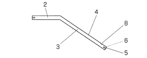
図1は、この考案の法面保護ブロックを備えた道路の一例を示す要部の斜視図である。道路の路肩部に設けられた法面保護ブロック1は、水平な上面を備えた路肩保護部2と、当該路肩保護部と一体の又は金具などで当該路肩保護部に連接された法面保護部3とを備えている。法面保護部3の表面は、路肩保護部2から下方に傾斜した傾斜表面4となっている。
FIG. 1 is a perspective view of a main part showing an example of a road provided with a slope protection block according to the present invention. The
図1に示す第1実施例の法面保護ブロック1の傾斜表面4の下縁近くには、当該下縁5と平行に1本の連続した水流減速溝8が設けられている。この水流減速溝8の断面は、図2に示すように、傾斜表面4を流下する水を堰き止める方向の衝突面10を備えた形状である。この衝突面10は、図3に示すように、溝8とその下側に設けた突条11とで丈高く形成することもできる。
In the vicinity of the lower edge of the
法面保護ブロックの下縁5と平行な溝8ないし突条11は、スリップフォーム工法により、施工現場で成形することができる。図4は、スリップフォーム工法で溝8を成形する例を示した図で、法面保護ブロック1の表面形状に応じた形状の型板21を現場打設コンクリートの表面に沿って滑らせてゆくことにより、溝8を含む法面保護ブロックの表面を成形する。溝8を成形する屈曲部22を複数設ければ、平行な複数の溝を成形でき、屈曲部22の屈曲方向を反対にすれば、突条を成形できる。
The
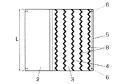
法面保護ブロック1は、工場で所定長さのブロックを成形して施工現場に並べ置くことによって施工することもできる。図5ないし図7は、図1の法面保護ブロック1の施工に用いる工場成形ブロックの例を示した図で、図5は平面図、図5は正面図、図7は側面図である。図の工場成形ブロックの路肩保護部2の反法面保護部側の縁の両端及び法面保護部3の下縁5の両端には、隣接する工場成形ブロック相互を連結する金具を取り付けるためのインサートナット6が埋め込まれている。図の工場成形ブロック1の道路延在方向の長さLは、約2mである。
The
水流減速溝8は、傾斜表面4の下縁5に近い位置に複数本設けることもできるし、傾斜表面4全体に分布させて複数本設けることもできる。図8ないし図10に示す第2実施例の工場成形ブロックは、傾斜表面4に第1実施例に示した連続直線状の水流減速溝8の複数本を等間隔で配置したものであり、図8は平面図、図9は正面図、図10は側面図である。
A plurality of water
第2実施例の路肩保護ブロックは、路肩保護部2の断面形状が第1実施例のものと異なっている。すなわち、この第2実施例の法面保護ブロックは、その路肩保護部2の表面の傾斜表面4側に段差13を備えており、この段差13の法面保護部3側が道路面から突出する道路の縁石となっている。
The road shoulder protection block of the second embodiment is different from that of the first embodiment in the cross-sectional shape of the road
水流減速溝8は、下縁5の延在方向に連続して屈曲した形状や、途切れ途切れの短い溝の集合として形成することもできる。図11は、第3実施例の工場成形ブロックを示した平面図で、第2実施例の複数本の水流減速溝8をU字を連続した屈曲溝とした例である。また、図12は、第4実施例の工場成形ブロックを示した平面図で、第2実施例の水流減速溝8をV字を連続した屈折溝とした例である。
The water
図13、図14及び図15は、第5実施例を示す平面図、正面図及び側面図で、路肩保護部2の断面形状が第2実施例と同じ構造のブロックについて、水流減速溝8の形成態様が異なるものを示したものである。この第5実施例のブロックでは、傾斜表面4の全体に亘って途切れ途切れに設けた不連続な三日月状の突起14・・・によって、当該突起14・・・の間に水流減速溝8を形成している。突起14は、傾斜表面4に千鳥状に分布しており、それらの突起14の間に形成される水流減速溝8は、ジグザグ状になっている。
13, FIG. 14 and FIG. 15 are a plan view, a front view and a side view showing the fifth embodiment, where the cross-sectional shape of the road
この第5実施例の水流減速溝8の作用は、第1実施例のもののように、水流を溝の壁面10に衝突させて水流を減速させるのではなく、水流が傾斜表面4上をジグザグ状に流れ、又は突起14・・・に乗り上げては水流減速溝8へと落下する流れを繰り返すことによって、水流の速度エネルギーを低減させることにより、減速させるものである。
The action of the water
以上、第1実施例から第5実施例について説明したが、この考案の法面保護ブロックにおける水流減速溝8ないし突起14の形状や構造は、第1ないし第5実施例に示したものに限定されるものではなく、傾斜表面4を流下する水流をブロックの下縁5の延在方向に連続的に、又は途切れ途切れに延在する溝の壁面に衝突させることにより、又は傾斜表面4に設けた多数の突起により、当該表面を流れる溝を平面的に又は立体的にジグザグ状に流すことによって、水流のエネルギーを吸収して傾斜表面4の下縁から流出する水流の速度を当該下縁の直下における土の法面の洗掘を有効に低減できる程度に減速させる形状や構造であれば、実施例に示したもの以外の種々の形状や構造が採用可能である。
Although the first to fifth embodiments have been described above, the shape and structure of the water
3 法面保護部
4 傾斜表面
5 下縁
8 水流減速溝
10 壁面
14 突起
3
10 Wall surface
14 Protrusions
Claims (5)
Priority Applications (1)
| Application Number | Priority Date | Filing Date | Title |
|---|---|---|---|
| JP2009003207U JP3152392U (en) | 2009-05-18 | 2009-05-18 | Slope protection block |
Applications Claiming Priority (1)
| Application Number | Priority Date | Filing Date | Title |
|---|---|---|---|
| JP2009003207U JP3152392U (en) | 2009-05-18 | 2009-05-18 | Slope protection block |
Publications (1)
| Publication Number | Publication Date |
|---|---|
| JP3152392U true JP3152392U (en) | 2009-07-30 |
Family
ID=54856711
Family Applications (1)
| Application Number | Title | Priority Date | Filing Date |
|---|---|---|---|
| JP2009003207U Expired - Lifetime JP3152392U (en) | 2009-05-18 | 2009-05-18 | Slope protection block |
Country Status (1)
| Country | Link |
|---|---|
| JP (1) | JP3152392U (en) |
Cited By (3)
| Publication number | Priority date | Publication date | Assignee | Title |
|---|---|---|---|---|
| JP2012136930A (en) * | 2010-12-08 | 2012-07-19 | Yamagata Shinko Kk | Road shoulder protecting block, road shoulder structure and cast-in-place concrete form |
| CN111663400A (en) * | 2020-07-09 | 2020-09-15 | 深圳市博耀新材料有限公司 | Pedestrian tunnel and multifunctional road shoulder thereof |
| CN114086511A (en) * | 2021-12-01 | 2022-02-25 | 冀相海 | Hydraulic engineering bank protection construction equipment |
-
2009
- 2009-05-18 JP JP2009003207U patent/JP3152392U/en not_active Expired - Lifetime
Cited By (3)
| Publication number | Priority date | Publication date | Assignee | Title |
|---|---|---|---|---|
| JP2012136930A (en) * | 2010-12-08 | 2012-07-19 | Yamagata Shinko Kk | Road shoulder protecting block, road shoulder structure and cast-in-place concrete form |
| CN111663400A (en) * | 2020-07-09 | 2020-09-15 | 深圳市博耀新材料有限公司 | Pedestrian tunnel and multifunctional road shoulder thereof |
| CN114086511A (en) * | 2021-12-01 | 2022-02-25 | 冀相海 | Hydraulic engineering bank protection construction equipment |
Similar Documents
| Publication | Publication Date | Title |
|---|---|---|
| JP3152392U (en) | Slope protection block | |
| CN213233719U (en) | Drainage structure is cut on slope earth's surface | |
| JP6041118B2 (en) | Sand blowing prevention structure | |
| KR101282914B1 (en) | Drainage system of pavement | |
| JP4628959B2 (en) | Catchment structure and drainage structure using the same | |
| JP3130944U (en) | Cross-type side gutter unit and side drainage type grating lid that do not require iron frame and iron receiving frame | |
| KR200422723Y1 (en) | Super grating | |
| US7052212B1 (en) | Downspout energy dissipater splash pad with spillway | |
| JP4080269B2 (en) | Drainage structure of the sidewalk | |
| JP5100163B2 (en) | Irrigation system | |
| JP2764544B2 (en) | Street lid for permeable pavement | |
| CN107090759A (en) | Two-stage road slope ditch component and two-stage road slope ditch structure | |
| CN108487415B (en) | Design method and application of slope drainage ditch, and drainage ditch | |
| CN113389104A (en) | Pavement drainage system and construction method thereof | |
| JP5936047B2 (en) | Sand blowing prevention structure | |
| JP5432317B2 (en) | Multifunctional protective fence with built-in drainage channel | |
| CN210288008U (en) | Two-stage road slope ditch component and two-stage road slope ditch structure | |
| JP3232449U (en) | Underdrain type gutter | |
| JP3127873U (en) | Side groove and lid structure | |
| KR100589444B1 (en) | Mounting structure of pavement block of collective building area | |
| JP4206006B2 (en) | Side groove block for permeable pavement | |
| KR20210021214A (en) | Eco-friendly side gutter structure for ridge of a mountain | |
| CN219772586U (en) | Urban road rainwater drainage system | |
| JP3232407U (en) | Upper and lower split type gutter | |
| JP2011047107A (en) | Sidewalk roadway boundary block, and sidewalk roadway boundary drainage structure |
Legal Events
| Date | Code | Title | Description |
|---|---|---|---|
| R150 | Certificate of patent or registration of utility model |
Free format text: JAPANESE INTERMEDIATE CODE: R150 |
|
| FPAY | Renewal fee payment (event date is renewal date of database) |
Free format text: PAYMENT UNTIL: 20120708 Year of fee payment: 3 |
|
| FPAY | Renewal fee payment (event date is renewal date of database) |
Free format text: PAYMENT UNTIL: 20120708 Year of fee payment: 3 |
|
| FPAY | Renewal fee payment (event date is renewal date of database) |
Free format text: PAYMENT UNTIL: 20130708 Year of fee payment: 4 |
|
| R250 | Receipt of annual fees |
Free format text: JAPANESE INTERMEDIATE CODE: R250 |
|
| R250 | Receipt of annual fees |
Free format text: JAPANESE INTERMEDIATE CODE: R250 |
|
| R250 | Receipt of annual fees |
Free format text: JAPANESE INTERMEDIATE CODE: R250 |
|
| R250 | Receipt of annual fees |
Free format text: JAPANESE INTERMEDIATE CODE: R250 |
|
| R250 | Receipt of annual fees |
Free format text: JAPANESE INTERMEDIATE CODE: R250 |
|
| EXPY | Cancellation because of completion of term |