JP3148549U - Mounting bracket - Google Patents
Mounting bracket Download PDFInfo
- Publication number
- JP3148549U JP3148549U JP2008008529U JP2008008529U JP3148549U JP 3148549 U JP3148549 U JP 3148549U JP 2008008529 U JP2008008529 U JP 2008008529U JP 2008008529 U JP2008008529 U JP 2008008529U JP 3148549 U JP3148549 U JP 3148549U
- Authority
- JP
- Japan
- Prior art keywords
- lighting fixture
- clamping
- mounting
- wall surface
- mounting bracket
- Prior art date
- Legal status (The legal status is an assumption and is not a legal conclusion. Google has not performed a legal analysis and makes no representation as to the accuracy of the status listed.)
- Expired - Lifetime
Links
Images

Landscapes
- Arrangement Of Elements, Cooling, Sealing, Or The Like Of Lighting Devices (AREA)
- Non-Portable Lighting Devices Or Systems Thereof (AREA)
Abstract
【課題】LED照明器具を回動可能に天井や壁面に取付ける金具を提供する。
【解決手段】該照明器具を挟持する一対の挟持部材と、該挟持部材の略中央部から延出し、且つ直角方向に立設する接続部と、該接続部と回動可能に接続し、前記照明器具を壁面等に取り付ける取り付け部材とから構成される。この一対の挟持部材は、半環状の板材からなり、前記照明器具の周囲から対向して挟持してねじ固定され、取り付け部材は、正面視略コの字形状に形成された板材からなり、前記照明器具の周囲から対向して挟持し、ねじ固定された挟持部材の接続部と、前記板材の先端部と接続部材によって回動可能に接続すると共に、該板材の中央部に設けられた取り付け孔部によって壁面等に取り付けられる。
【選択図】 図1An object of the present invention is to provide a metal fitting for rotatably mounting an LED lighting fixture on a ceiling or a wall surface.
A pair of clamping members for clamping the lighting fixture, a connection portion extending from a substantially central portion of the clamping member and standing in a perpendicular direction, and a connection with the connection portion so as to be rotatable, It is comprised from the attachment member which attaches a lighting fixture to a wall surface etc. The pair of clamping members are made of a semi-annular plate material, are clamped by being opposed from the periphery of the lighting fixture, and the mounting member is made of a plate material formed in a substantially U shape in front view, An attachment hole provided in a central portion of the plate member, which is rotatably connected by a connecting member of a clamping member, which is clamped oppositely from the periphery of the lighting fixture, and a distal end portion of the plate member and the connecting member. It is attached to the wall surface etc. by the part.
[Selection] Figure 1
Description
本考案は、取付け金具であって、とくにLED照明器具を天井や壁面に取付けて、この照明器具を回動自在とすることによって、光照射方向を変更可能な取付け金具に関するものである。 The present invention relates to a mounting bracket, and more particularly, to a mounting bracket that can change the light irradiation direction by mounting an LED lighting fixture on a ceiling or a wall and making the lighting fixture rotatable.
LEDは消費電力が少なく、高輝度であると共に、長期間の使用ができることから、近年LEDを光源とした照明器具が工場や事業所内、或いは一般家庭において数多く採り入れられている。 Since LEDs have low power consumption, high luminance, and can be used for a long time, in recent years, many lighting fixtures using LEDs as light sources have been adopted in factories, offices, or general households.
しかしながら、LEDを使用してより高い光強度を実現するためには、多くのLED素子を使用する構成となるため、必然的にこの素子からの発熱量も大きなものとなり、放熱のための様々な手段が採られるため、照明器具の形状も複雑となり、とくに天井や壁面に取付ける際の制約となった。 However, in order to achieve a higher light intensity using an LED, a configuration in which many LED elements are used, the amount of heat generated from this element is inevitably large, and various types of heat dissipation are required. Since the measures are taken, the shape of the luminaire is also complicated, especially when it is mounted on the ceiling or wall.
照明器具を天井に取付ける手段としては、一般に引掛けシーリングやローゼットが挙げられるが、いずれもコードによって照明器具の重量を支える方式であり重量のある照明器具に対しては問題があった。そこで天井等に直接固定される吊下装置本体と、この吊下装置本体に両端に一体に配設、形成される保持部或は保持溝にグローブと一体となる照明器具本体に固定される取付部を有する二本のハンガーを掛止し、或は掛止した上で、スライドプレート或はロックバネにより固持する吊下装置が提案されている(特許文献1参照。)。 As a means for attaching the lighting fixture to the ceiling, there is generally a hanging ceiling or a rosette, but any of them is a method of supporting the weight of the lighting fixture by a cord, and there is a problem with a heavy lighting fixture. Therefore, the suspension device main body directly fixed to the ceiling or the like, and the attachment fixed to the lighting fixture main body integrated with the globe in the holding portion or the holding groove formed integrally with both ends of the suspension device main body. A suspension device has been proposed in which two hangers having a portion are hooked or hooked and then held by a slide plate or a lock spring (see Patent Document 1).
しかしながら、上記特許文献1に提案されている吊下装置は、従来の照明器具を天井に取付ける装置と比較して重量のあるものでも、安定して吊下げができるものであるが、取付けた後で、照射方向を変更できる構造ではなかった。また、天井内に組み込んでダウンライトとして利用する構造も多数提案されているが、いずれも光源を固定する方式がほとんどであった。
However, the suspension device proposed in
上記の問題点に鑑み本考案者は、天井や壁面に取付ける際の制約となった、複雑な形状の照明器具を、簡単な構造によって取り付けると共に、この照明器具の光照射方向を変更できる取付け金具を提供するに至った。 In view of the above-mentioned problems, the inventor attaches a lighting fixture having a complicated shape, which has been a restriction when mounting to a ceiling or a wall, with a simple structure and can change the light irradiation direction of the lighting fixture. It came to offer.
このため、本考案の取付け金具は、LED照明器具の取付け金具であって、該照明器具を挟持して固定する一対の挟持部材と、該挟持部材の略中央部から延出し、且つ直角方向に立設する接続部と、該接続部と回動可能に接続し、前記照明器具を壁面に取り付ける取り付け部材とから構成されることを特徴とする。 For this reason, the mounting bracket of the present invention is a mounting bracket for LED lighting fixtures, a pair of clamping members for clamping and fixing the lighting fixtures, extending from a substantially central portion of the clamping members, and in a perpendicular direction. It is comprised from the connection part to stand, and the attachment member which connects with this connection part so that rotation is possible, and attaches the said lighting fixture to a wall surface.
また、前記一対の挟持部材は、半環状の板材からなり、前記照明器具の周囲から対向して挟持し、ねじ固定されることを特徴とする。 Further, the pair of clamping members are made of a semi-annular plate material, are opposed to each other from the periphery of the lighting fixture, and are fixed by screws.
そして、前記取り付け部材は、正面視略コの字形状に形成された板材からなり、前記照明器具の周囲から対向して挟持し、ねじ固定された挟持部材の接続部と、前記板材の先端部と接続部材によって回動可能に接続すると共に、該板材の中央部に設けられた取り付け孔部によって壁面に取り付けられることを特徴とする。 The attachment member is made of a plate material formed in a substantially U-shape when viewed from the front, and is sandwiched and opposed from the periphery of the lighting fixture, and is connected with a screw-fixed connection member and a tip portion of the plate material And a connecting member so as to be rotatable, and is attached to a wall surface by an attachment hole provided in a central portion of the plate member.
本考案に係る取付け金具によれば、照明器具を挟持して固定する一対の挟持部材と、該挟持部材の略中央部から延出し、且つ直角方向に立設する接続部と、該接続部と回動可能に接続し、前記照明器具を壁面に取り付ける取り付け部材とから構成されているため、LED照明器具に不可欠な放熱手段(例えば放熱フィン)があっても取付が容易となるという効果を有する。 According to the mounting bracket according to the present invention, a pair of clamping members for clamping and fixing a lighting fixture, a connection portion extending from a substantially central portion of the clamping member and standing in a perpendicular direction, and the connection portion Since it is comprised from the attachment member which connects so that rotation is possible and attaches the said lighting fixture to a wall surface, it has the effect that attachment is easy even if there exists a heat dissipation means (for example, heat dissipation fin) indispensable to LED lighting fixture .
しかも、照明器具を壁面に取付けた後でも光照射方向を変更することが可能であるという効果を有する。 And it has the effect that a light irradiation direction can be changed even after attaching a lighting fixture to a wall surface.
以下、本考案を実施例を示す図面を参照しながら説明するが、本考案が本実施例に限定されないことは言うまでもない。図1は、本考案の取付け金具の一実施例を示す説明図、図2は本考案の取付け金具の使用例を示す斜視図、図3は他の実施例を示す斜視図である。 Hereinafter, although this invention is demonstrated, referring drawings which show an Example, it cannot be overemphasized that this invention is not limited to a present Example. FIG. 1 is an explanatory view showing an embodiment of the mounting bracket of the present invention, FIG. 2 is a perspective view showing an example of use of the mounting bracket of the present invention, and FIG. 3 is a perspective view showing another embodiment.
図1は本考案の取付け金具1を示す説明図であり、(a)は側面図、(b)は正面図、(c)は平面説明図、(D)は底面説明図である。図に示すように取付け金具1は、一対の半環状に形成されたステンレス材からなる挟持部材2と、この挟持部材2の中央部から径方向に延出して直角方向に折曲して形成された接続部3と、この接続部3にボルトによって接続する取付部材4とから構成されている。
1A and 1B are explanatory views showing a
挟持部材2には、照明器具(破線表示)に取付ける孔部5が複数穿設されており、照明器具を挟持して固定する際にビスが嵌入される。また挟持部材2の中央部から径方向に延出して直角方向に折曲して形成された接続部3には、後述する取付部材4を接続するボルト6を挿通する孔部(図示せず)が穿設されており、このボルト6周りに180度回転可能とされている。
The
取付部材4は、ステンレス製で正面視コの字形状に形成された板材であり、上記の照明器具に環状に取付けた挟持部材2の孔部と対向して、両端部に孔部(図示せず)が穿設されており、上記したボルト6によって回動可能に固定される。そして、中央部には複数の取付用孔7が穿設されており、取付ボルトによって壁面などに取付られる。
The
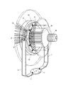
図2は、本考案の取付け金具1を照明器具に取付けた状態を示している。図に示すように、照明器具8の側面及び後面には、光源であるLED(図示せず)の放熱のための放熱リング9が多数取付けられており、この放熱リング9の間に2枚の挟持部材2が対向して取付けられ、ビス10によって固定されている。挟持部材2の両端には、それぞれ接続部3が延出して直角方向に折曲して形成されており、この接続部3と取付部材4とがボルト6を介して回動可能に固定される。そして、取付部材4の中央部の取付孔7に取付ボルト11が挿通し、壁面等に取付られる。
FIG. 2 shows a state in which the
上記の構成からなる、本考案の取付け金具は、一対の挟持部材によって照明器具を挟持して固定するため、放熱リングのある照明器具であっても、短時間で取付けることが可能であり、またこの挟持部材から延出する接続部と取付部材によって、壁面等に取り付けるがことができる。しかも、挟持部材は取付部材に対して回動可能であるため、照明器具は壁面に取付けた後でも、光照射方向を変更可能となる。尚、本実施例においては180度回動する構成であるが、挟持部材の接続部形状を変えることによって360度回動する構成とすることも可能である。 The mounting bracket according to the present invention having the above-described configuration sandwiches and fixes a lighting fixture by a pair of clamping members, so that even a lighting fixture having a heat dissipation ring can be installed in a short time. It can be attached to a wall surface or the like by a connecting portion and an attachment member extending from the sandwiching member. In addition, since the clamping member can be rotated with respect to the attachment member, the light illumination direction can be changed even after the lighting fixture is attached to the wall surface. Although the present embodiment is configured to rotate 180 degrees, it may be configured to rotate 360 degrees by changing the shape of the connecting portion of the clamping member.
以上、本考案の取付け金具によれば、天井や壁面に取付ける際の制約となった、複雑な形状の照明器具を、簡単な構造によって取り付けると共に、この照明器具の光照射方向を変更できる。 As described above, according to the mounting bracket of the present invention, it is possible to mount a lighting device having a complicated shape, which is a restriction when mounting on a ceiling or a wall surface, with a simple structure and to change the light irradiation direction of the lighting device.
1 取付け金具
2 挟持部材
3 接続部
4 取付部材
5 孔部
6 ボルト
7 取付用孔
8 照明器具
9 放熱リング
10 ビス
DESCRIPTION OF
Claims (3)
Priority Applications (1)
| Application Number | Priority Date | Filing Date | Title |
|---|---|---|---|
| JP2008008529U JP3148549U (en) | 2008-12-05 | 2008-12-05 | Mounting bracket |
Applications Claiming Priority (1)
| Application Number | Priority Date | Filing Date | Title |
|---|---|---|---|
| JP2008008529U JP3148549U (en) | 2008-12-05 | 2008-12-05 | Mounting bracket |
Publications (1)
| Publication Number | Publication Date |
|---|---|
| JP3148549U true JP3148549U (en) | 2009-02-19 |
Family
ID=54782091
Family Applications (1)
| Application Number | Title | Priority Date | Filing Date |
|---|---|---|---|
| JP2008008529U Expired - Lifetime JP3148549U (en) | 2008-12-05 | 2008-12-05 | Mounting bracket |
Country Status (1)
| Country | Link |
|---|---|
| JP (1) | JP3148549U (en) |
Cited By (1)
| Publication number | Priority date | Publication date | Assignee | Title |
|---|---|---|---|---|
| JP2013160006A (en) * | 2012-02-07 | 2013-08-19 | Toei Kanki Kk | Joint with seat |
-
2008
- 2008-12-05 JP JP2008008529U patent/JP3148549U/en not_active Expired - Lifetime
Cited By (1)
| Publication number | Priority date | Publication date | Assignee | Title |
|---|---|---|---|---|
| JP2013160006A (en) * | 2012-02-07 | 2013-08-19 | Toei Kanki Kk | Joint with seat |
Similar Documents
| Publication | Publication Date | Title |
|---|---|---|
| US9557022B2 (en) | Non-round retrofit recessed LED lighting fixture | |
| US20110024593A1 (en) | Fixture support system and method | |
| US20140268724A1 (en) | Rotational mounting for linear led light | |
| CA2570789A1 (en) | Lighting fixture with smooth adjustable beam width | |
| CA2804563C (en) | Downlight support | |
| JP2014139933A (en) | Clipping joint structure | |
| JP4616411B1 (en) | LED lamp illuminating device and connecting jig used therefor, LED lamp holder and straight tube type LED lamp | |
| KR101806869B1 (en) | Ceiling lights | |
| RU134612U1 (en) | SHAPED PROFILE FOR LED LUMINAIRES, LED LUMINAIRES, MOUNTING FIXTURE OF THE LUMINAIRES TO THE EXTERNAL SUSPENSION AND CONNECTOR FOR THE MECHANICAL CONNECTION OF LED LUMINAIRES | |
| US6494601B2 (en) | Modular cluster lighting fixture | |
| JP3148549U (en) | Mounting bracket | |
| US20230051946A1 (en) | Modular, Recessed Lighting System | |
| RU174416U1 (en) | Device for fixing the lamp | |
| RU101776U1 (en) | Recessed luminaire | |
| JP4830926B2 (en) | Recessed lighting fixture | |
| KR101663052B1 (en) | LED ceiling lights | |
| KR101537160B1 (en) | Illuminating Lighting Device able to easily rotate and connect | |
| KR200334562Y1 (en) | Structure for combing cylindrical reflecting hat of illuminator | |
| KR101263011B1 (en) | Angle-adiustable lighting apparatus | |
| CN215722862U (en) | Lamp set | |
| KR200449045Y1 (en) | Lamp device depending from the ceiling | |
| CN203927587U (en) | A kind of Down lamp | |
| US9341351B2 (en) | Universal mounting system for pole mounted area lights | |
| CN218626686U (en) | Combined lighting lamp | |
| CN211116692U (en) | Fan lamp |
Legal Events
| Date | Code | Title | Description |
|---|---|---|---|
| R150 | Certificate of patent or registration of utility model |
Free format text: JAPANESE INTERMEDIATE CODE: R150 |
|
| FPAY | Renewal fee payment (event date is renewal date of database) |
Free format text: PAYMENT UNTIL: 20120128 Year of fee payment: 3 |
|
| FPAY | Renewal fee payment (event date is renewal date of database) |
Free format text: PAYMENT UNTIL: 20190128 Year of fee payment: 10 |
|
| S531 | Written request for registration of change of domicile |
Free format text: JAPANESE INTERMEDIATE CODE: R323531 |
|
| R350 | Written notification of registration of transfer |
Free format text: JAPANESE INTERMEDIATE CODE: R350 |
|
| EXPY | Cancellation because of completion of term |