JP3147874U - Alarm - Google Patents
Alarm Download PDFInfo
- Publication number
- JP3147874U JP3147874U JP2008007777U JP2008007777U JP3147874U JP 3147874 U JP3147874 U JP 3147874U JP 2008007777 U JP2008007777 U JP 2008007777U JP 2008007777 U JP2008007777 U JP 2008007777U JP 3147874 U JP3147874 U JP 3147874U
- Authority
- JP
- Japan
- Prior art keywords
- alarm
- fire
- lighting
- brightness
- sensor
- Prior art date
- Legal status (The legal status is an assumption and is not a legal conclusion. Google has not performed a legal analysis and makes no representation as to the accuracy of the status listed.)
- Expired - Lifetime
Links
- 238000005286 illumination Methods 0.000 claims abstract description 57
- 238000012544 monitoring process Methods 0.000 claims abstract description 45
- 238000001514 detection method Methods 0.000 claims abstract description 34
- 230000005856 abnormality Effects 0.000 claims description 22
- 238000012360 testing method Methods 0.000 claims description 5
- 230000009467 reduction Effects 0.000 abstract description 11
- 238000000034 method Methods 0.000 description 19
- 230000008569 process Effects 0.000 description 17
- 230000005540 biological transmission Effects 0.000 description 16
- 239000000779 smoke Substances 0.000 description 11
- 230000006870 function Effects 0.000 description 9
- 238000012545 processing Methods 0.000 description 5
- 238000007689 inspection Methods 0.000 description 4
- 230000004397 blinking Effects 0.000 description 3
- 238000004891 communication Methods 0.000 description 3
- 238000010586 diagram Methods 0.000 description 3
- 238000009434 installation Methods 0.000 description 3
- 230000008901 benefit Effects 0.000 description 2
- 206010037660 Pyrexia Diseases 0.000 description 1
- 230000015572 biosynthetic process Effects 0.000 description 1
- 238000010276 construction Methods 0.000 description 1
- 230000003247 decreasing effect Effects 0.000 description 1
- 230000000977 initiatory effect Effects 0.000 description 1
- 230000001678 irradiating effect Effects 0.000 description 1
- 238000012986 modification Methods 0.000 description 1
- 230000004048 modification Effects 0.000 description 1
- 239000011347 resin Substances 0.000 description 1
- 229920005989 resin Polymers 0.000 description 1
- 238000003786 synthesis reaction Methods 0.000 description 1
- 230000001960 triggered effect Effects 0.000 description 1
- 239000002699 waste material Substances 0.000 description 1
Images


Landscapes
- Fire Alarms (AREA)
Abstract
【課題】避難経路を確保する必要がある場合にのみ照明装置を駆動可能として不必要な電池消耗による機能喪失を防ぐようにした警報器を提供する。【解決手段】警報器10−1は、火災センサ部34により監視エリアの火災を検出して報知部36により警報する。警報器10−1には、監視エリアの一部または全部を照明する照明装置24と、監視エリアの照度を検出する明暗センサ26が設けられ、照明制御部62は、火災センサ部34又は他の警報器10−2〜10−5による検出と明暗センサ26による明るさ低下検出に基づいて照明装置24を駆動させる。即ち照明制御部62は、火災検出と明るさ低下検出の両方が判別された時に照明装置24を駆動する。【選択図】図3The present invention provides an alarm device that can drive a lighting device only when it is necessary to secure an evacuation route to prevent loss of function due to unnecessary battery consumption. An alarm device 10-1 detects a fire in a monitoring area by a fire sensor unit 34 and issues an alarm by a notification unit 36. The alarm device 10-1 is provided with a lighting device 24 that illuminates a part or all of the monitoring area, and a light / dark sensor 26 that detects the illuminance of the monitoring area. The lighting device 24 is driven based on the detection by the alarm devices 10-2 to 10-5 and the brightness decrease detection by the brightness sensor 26. That is, the illumination control unit 62 drives the illumination device 24 when both fire detection and brightness reduction detection are determined. [Selection] Figure 3
Description
本考案は、火災やガス漏れなどの異常を検出して警報する警報器に関する。
The present invention relates to an alarm device for detecting and alarming an abnormality such as a fire or gas leak.
従来、住宅における火災やガス漏れなどの異常を検出して警報する住宅用警報器(以下「住警器」という)が普及しており、近年にあっては、1つの住戸に複数の住警器を設置して部屋毎に火災などの異常を監視する傾向も増加している。 Conventionally, residential alarm devices (hereinafter referred to as “residential alarms”) that detect and warn of abnormalities such as fires and gas leaks in homes have become widespread. There is also an increasing tendency to monitor the anomalies such as fires in each room by installing a vessel.
このように住戸内に複数の住警器を設置した場合、異常が発生した部屋とは別の部屋に人がいた場合、警報音が聞こえず火災などの災害が広がる恐れがある。このため、住警器間で通信させ、ある住警器で火災を検出して警報した場合、有線又は無線により他の住警器に信号を送って同時に警報させる連動警報ができるようにしている。 In this way, when a plurality of house alarms are installed in a dwelling unit, if a person is in a room different from the room where the abnormality has occurred, a warning sound may not be heard and a disaster such as a fire may spread. For this reason, when a fire alarm is detected and alarmed by a certain resident alarm, communication is made between the resident alarms, so that a linked alarm can be made to send a signal to other resident alarms by wire or wirelessly to make an alarm at the same time. .
また住警器に照明装置を設け、停電時に非常灯として点灯させるものや(特許文献1)、火災を検出した時に発光表示部を作動して床面に向けて光を照射し、照明が消されている夜間などに火災が発生した場合の避難を行いやすくしたもの(特許文献2)が提案されている。
しかしながら、このような従来の警報器にあっては、監視エリアの明るさに関係なく火災を検出した時に照明装置を駆動して監視エリアを照明するようにしており、必要以上に照明が行われ、また多くの場合警報器は電池で駆動されており、照明装置の駆動により必要を超えて電池が消耗する問題がある。 However, in such a conventional alarm device, when a fire is detected regardless of the brightness of the monitoring area, the lighting device is driven to illuminate the monitoring area, and the illumination is performed more than necessary. In many cases, the alarm device is driven by a battery, and there is a problem that the battery is consumed more than necessary by driving the lighting device.
一方、特許文献1のものにあっては、照明装置を駆動する夜間の時間帯を設定するようにしているが、実際の住宅内の監視エリアが照明を必要とする暗さとなるのは季節により異なり、また外部から光が入りにくい場所にあっては、照明を必要とする時間帯の設定をどのようにするか判断に迷う場合があり、不適切な時間帯を設定した場合には必要なときに照明装置が駆動しないおそれもある。 On the other hand, in the thing of patent document 1, it is trying to set the night time zone which drives an illuminating device, but it is dark according to a season that the monitoring area in an actual house becomes the darkness which needs lighting. It is difficult to determine how to set the time zone that requires lighting in places where light is difficult to enter from the outside, and this is necessary if an inappropriate time zone is set. Sometimes the lighting device may not be driven.
本考案は、監視エリアの状況に応じて必要がある場合にのみ照明装置を駆動可能として不必要な電池消耗による機能喪失を防ぐようにした警報器を提供することを目的とする。
SUMMARY OF THE INVENTION An object of the present invention is to provide an alarm device that can drive a lighting device only when it is necessary according to the situation of a monitoring area to prevent loss of function due to unnecessary battery consumption.
本考案は、センサ部により監視エリアの異常を検出して報知部により警報する警報器に於いて、
監視エリアの一部または全部を照明する照明装置と、
監視エリアの明るさを検出する明暗センサと、
センサ部による異常検出と明暗センサによる明るさ検出に基づいて照明装置を駆動する照明制御部と、
を備えたことを特徴とする。
The present invention is an alarm device that detects an abnormality in a monitoring area by a sensor unit and alarms by a notification unit.
A lighting device that illuminates part or all of the monitoring area;
A brightness sensor that detects the brightness of the monitoring area;
An illumination control unit that drives the illumination device based on the abnormality detection by the sensor unit and the brightness detection by the brightness sensor;
It is provided with.
ここで、照明制御部は、センサ部又は他の警報器による異常検出が判別された時、明暗センサによる明るさ検出レベルが所定値以下の場合に照明装置を駆動する。 Here, the illumination control unit drives the illumination device when the abnormality detection by the sensor unit or another alarm device is determined and the brightness detection level by the brightness sensor is equal to or less than a predetermined value.
照明制御部は、センサ部又は他の警報器による異常検出から照明点灯に至るまでに、遅延時間を設ける。 The illumination control unit provides a delay time from the detection of abnormality by the sensor unit or other alarm device to the lighting of the illumination.
照明制御部は、照明装置の駆動を開始した後、駆動状態を少なくとも所定期間保持する。 The lighting control unit holds the driving state for at least a predetermined period after starting the driving of the lighting device.
照明制御部は、記照明装置の駆動中に警報停止操作を判別した時に、照明装置の駆動を停止する。 The illumination control unit stops the driving of the lighting device when the alarm stop operation is determined during the driving of the lighting device.
照明制御部は、試験操作を判別した時に、照明装置を一時的に駆動する。 The illumination controller temporarily drives the illumination device when determining the test operation.
照明制御部は、照明駆動中に警報停止操作を判別した場合にも、駆動状態を少なくとも所定期間保持する。 The lighting control unit holds the driving state for at least a predetermined period even when the alarm stop operation is determined during the lighting driving.
照明制御部は、照明駆動開始遅延時間中に警報停止の操作を判別した場合には照明装置の駆動を行わない。
The lighting control unit does not drive the lighting device when it determines an alarm stop operation during the lighting driving start delay time.
本考案によれば、火災などの異常を検出し、且つ明暗センサにより明るさ低下検出が行われた場合にのみ照明装置を駆動して監視エリアの一部または全部を照明して安全に避難できるようにし、照明の必要のないたとえば昼間は照明装置を駆動しないようにして不必要な電池消耗を回避することができる。 According to the present invention, it is possible to safely evacuate by illuminating a part or all of the monitoring area by driving the illumination device only when an abnormality such as a fire is detected and the brightness reduction is detected by the brightness sensor. In this way, it is possible to avoid unnecessary battery consumption by not driving the lighting device in the daytime when no lighting is required.
また照明装置の駆動開始に遅延時間を設け、この時間内に警報停止操作を判別した場合には照明装置の駆動を行わないようにし、誤報や非火災報による不必要な電池消耗の可能性を低減することができる。
また一度照明装置を駆動したら所定時間の間は駆動状態を保持することにより、照明装置の駆動状態を安定させることができる。
In addition, a delay time is provided at the start of driving the lighting device, and if an alarm stop operation is determined within this time, the lighting device is not driven, and there is a possibility of unnecessary battery consumption due to false or non-fire reports. Can be reduced.
Further, once the lighting device is driven, the driving state of the lighting device can be stabilized by maintaining the driving state for a predetermined time.
また照明駆動中に警報停止操作を判別しても、少なくとも所定期間駆動状態を保持するので、避難途中で警報停止操作があった場合でも、直ちに照明が消えて視界を失う危険が無い。そして、通常照明モード中の足下照明等が、警報停止により直ちに消灯されることも無い。 Even if an alarm stop operation is determined during illumination driving, the driving state is maintained for at least a predetermined period. Therefore, even if an alarm stop operation is performed during evacuation, there is no risk that the illumination will immediately turn off and lose visibility. And the foot lighting in the normal lighting mode is not immediately turned off by the alarm stop.
また照明駆動開始までに遅延時間を設けているので、誤報や非火災報のときは遅延時間内に警報停止操作すれば、照明駆動による無駄な電力消費を抑制できる。
In addition, since a delay time is provided before the start of illumination driving, wasteful power consumption due to illumination driving can be suppressed if an alarm stop operation is performed within the delay time in the case of misinformation or non-fire information.
図1は本考案による無線式の住警器の外観を示した説明図であり、図1(A)に正面図を、図1(B)に側面図を示している。 FIG. 1 is an explanatory view showing the appearance of a wireless residence guard according to the present invention. FIG. 1 (A) shows a front view and FIG. 1 (B) shows a side view.
図1において、本実施形態の住警器10はカバー12と本体14で構成されている。カバー12の中央には、周囲に煙流入口を開口した検煙部16が配置され、火災による煙が所定濃度に達したときに火災を検出するようにしている。
In FIG. 1, the residential alarm 10 according to the present embodiment includes a
カバー12に設けた検煙部16の左下側には音響穴18が設けられ、この背後にブザー又はスピーカを内蔵し、警報音や音声メッセージを出力できるようにしている。カバー12の上部には警報表示部として動作するLED22が配置されている。検煙部16の下側には警報停止スイッチ20が設けられている。警報停止スイッチ20は警報器の機能を試験指示する点検スイッチとしての機能を兼ねている。
An acoustic hole 18 is provided on the lower left side of the
警報停止スイッチ20の内部には、点線で示すように照明装置24が配置されており、照明装置24が点灯すると、警報停止スイッチ20の半透明樹脂製スイッチカバーの部分を透過して照明光を外部に照射し、住警器を設置している監視エリアの一部又は全部を照明する。照明装置24としては例えば白色LEDが使用され、少ない消費電力で充分な照明光を照射して監視エリアを照明することができる。
An
カバー12の右上部には明暗センサ26が配置される。明暗センサ26は監視エリアの照度を検出して明るさ検出信号を出力する。明暗センサ26としては、たとえばフォトダイオードを用いるものなど、公知の技術が適用できる。
A light / dark sensor 26 is disposed on the upper right portion of the
また本体14の裏側上部には取付フック15が設けられており、設置する部屋の壁にビスなどをねじ込み、このビスに取付フック15を引っ掛けるなどして取り付けることで、壁面に住警器10を設置することができる。本実施例では壁面設置型としているが、天井に取り付ける形態の住警器もある。 A mounting hook 15 is provided at the upper part on the back side of the main body 14, and a screw or the like is screwed into the wall of the room to be installed, and the mounting hook 15 is hooked on the screw to attach the housing alarm 10 to the wall surface. Can be installed. Although the wall-mounted type is used in the present embodiment, there is also a residence guard that is attached to the ceiling.
なお、照明装置24の設置位置は警報停止スイッチ20の内部に限らず、カバー12の任意の位置に配置することができ、また照明方向は例えば床面に向くように固定しても良いし、任意の照明方向を向くように調整自在に配置しても良い。
The installation position of the
また図1の住警器10にあっては、検煙部16を備えた火災による煙を検出する住警器を例に取っているが、これ以外に火災による熱を検出する、たとえばサーミスタを備えた住警器や、火災以外にガス漏れを検出する住警器についても、本考案の対象に含まれる。
Moreover, in the residential alarm 10 of FIG. 1, although the residential alarm which detects the smoke by the fire provided with the
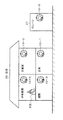
図2は住宅を対象とした本考案による住警器の設置状態を示した説明図である。図2にあっては、住宅25に設けられている台所、居間、主寝室、子供部屋のそれぞれに住警器10−1〜10−4が設置され、更に屋外に建てられたガレージ27にも住警器10−5を設置している。
FIG. 2 is an explanatory view showing an installation state of a house alarm device according to the present invention for a house. In FIG. 2, residence guards 10-1 to 10-4 are installed in the kitchen, living room, main bedroom, and children's room provided in the house 25, and also in a
住警器10−1〜10−5のそれぞれは、イベント信号を相互に無線により送受信する機能と警報を出力表示する機能を備えており、5台の住警器10−1〜10−5で1つの警報グループを構成して、この住宅全体の火災監視を行っている。なお無線式でなく有線接続式の住警器システムや無線式通信と有線式通信を混在させた住警器システムにも本考案の技術を適用できる。 Each of the home alarm devices 10-1 to 10-5 has a function of transmitting / receiving event signals wirelessly and a function of outputting and displaying an alarm, and the five home alarm devices 10-1 to 10-5 are provided. One alarm group is formed to monitor the fire of the entire house. Note that the technique of the present invention can be applied to a house alarm system that is wired instead of wireless, or a house alarm system that mixes wireless communication and wired communication.
いま住宅25の子供部屋で万一、火災が発生したとすると、住警器10−4が火災を検出して警報を開始する。この火災を検出して警報を開始することを、住警器における「発報」という。住警器10−4が発報すると、住警器10−4は連動元として機能し、連動先となる他の住警器10−1〜10−3,10−5に対し、火災発報を示すイベント信号を無線により送信する。他の住警器10−1〜10−3,10−5にあっては、連動元の住警器10−4からの火災発報を示すイベント信号を受信すると、連動先としての警報動作を行う。 If a fire has occurred in the child room of the house 25, the residence guard 10-4 detects the fire and starts an alarm. Detecting this fire and initiating an alarm is referred to as “reporting” at the home alarm. When the resident alarm 10-4 is triggered, the resident guard 10-4 functions as an interlocking source, and fires are issued to the other resident alarms 10-1 to 10-3 and 10-5 that are the interlocking destinations. An event signal indicating is transmitted by radio. In the other home alarm devices 10-1 to 10-3, 10-5, when receiving an event signal indicating a fire alarm from the home alarm device 10-4 as the interlock source, the alarm operation as the interlock destination is performed. Do.
ここで連動元となった住警器10−4の警報音としては、例えば音声メッセージにより「ウーウー 火災警報器が作動しました 確認してください」を連続して出力する。一方、連動先の住警器10−1〜10−3,10−5にあっては、「ウーウー 別の火災警報器が作動しました 確認してください」といった音声メッセージを連続して出力する。音声メッセージに依らず、異なるブザー音や、ブザー音と共に視覚的に連動元と連動先を識別出来る表示を併用することも考えられる。 Here, as the alarm sound of the home alarm device 10-4 that is the link source, for example, “Please confirm that the Woo fire alarm has been activated” is continuously output by voice message. On the other hand, in the interlocked residence alarm devices 10-1 to 10-3 and 10-5, a voice message such as “Please confirm that another fire alarm has been activated” is output continuously. Regardless of the voice message, it may be possible to use a different buzzer sound or a display that can visually identify the interlock source and the interlock destination together with the buzzer sound.
このように火災検出を判別して警報音を出力した住警器10−1〜10−5は、更に、明暗センサ29の明るさ検出信号に基づき、明るさ低下検出が判別されたときに照明装置24を駆動して監視エリアを照明する。
Thus, the residential alarm devices 10-1 to 10-5 that have determined fire detection and output an alarm sound further illuminate when a decrease in brightness is determined based on the brightness detection signal of the brightness sensor 29. The
住警器10−1〜10−5が警報音を出している状態で、図1に示した住警器に設けている警報停止スイッチ20を操作すると、警報音の停止処理が行われる。
When the
図3は本考案による警報システムを構築する住警器の構成を他の住警器と共に示したブロック図である。図3の警報システムは図2に示した5台の住警器10−1〜10−5につき、その内の住警器10−1について内部処理ブロック構成を詳細に示している。 FIG. 3 is a block diagram showing the construction of a home alarm device for constructing an alarm system according to the present invention together with other home alarm devices. The alarm system of FIG. 3 shows the internal processing block configuration in detail for the five home alarm devices 10-1 to 10-5 shown in FIG.
住警器10−1はCPU28を備え、CPU28に対してはアンテナ31を備えた無線回路部30、メモリ32、火災センサ部34、人感センサ26、明暗センサ29、報知部36、照明装置24、操作部38及び電池電源40を設けている。
The home alarm device 10-1 includes a
無線回路部30には送信回路42と受信回路44が設けられ、他の住警器10−2〜10−5との間でイベント信号を無線により送受信できるようにしている。無線回路部30としては、日本国内の場合には、例えば400MHz帯の特定小電力無線局の標準規格として知られたSTD−30(小電力セキュリティシステムの無線局の無線設備の標準規格)またはSTD−T67(特定小電力無線局テレメータ用、テレコントロール用及びデータ伝送用無線設備の標準規格)に準拠した構成を備える。 The wireless circuit unit 30 is provided with a transmission circuit 42 and a reception circuit 44 so that event signals can be transmitted and received wirelessly between the other mortgages 10-2 to 10-5. As the radio circuit unit 30, in Japan, for example, STD-30 (standard standard of radio equipment of a low power security system radio station) or STD known as a standard of a specific low power radio station of 400 MHz band or STD. -It has a configuration compliant with T67 (standard for specific low-power radio station telemeter, telecontrol and data transmission radio equipment).
もちろん無線回路部30としては、日本国内以外の場所については、その地域の割当無線局の標準規格に準拠した内容を持つことになる。 Of course, the radio circuit unit 30 has contents conforming to the standard of the assigned radio station in the area in places other than Japan.
メモリ32には住警器を特定するID(識別子)となる送信元符号50と、図2のように複数の住警器で連動警報を行うグループを構成するためのグループ符号52が格納されている。送信元符号50としては、国内に提供される住警器の数を予測し、例えば同一符号として重複しないように26ビットの符号コードが使用される。
The memory 32 stores a
グループ符号52はグループを構成する複数の住警器に共通に設定される符号であり、無線回路部30で受信した他の住警器からのイベント信号に含まれるグループ符号がメモリ46に登録しているグループ符号52に一致したときに、このイベント信号を有効な信号として受信して処理することになる。
The
警報グループの識別は、グループ符号以外に、住警器を特定するIDである送信元符号を使用してもよい。即ち、グループを構成する複数の住警器に、同じグループに属する他の住警器の送信元符号を予め登録しておき、他の住警器から受信したイベント信号に含まれる送信元符号を登録済み送信元符号と比較し、一致したら同じグループに属する住警器からの信号として処理する。 The identification of the alarm group may use a transmission source code that is an ID for identifying a residential alarm in addition to the group code. In other words, the source codes of other house alarm devices belonging to the same group are registered in advance in the plurality of house alarm devices constituting the group, and the source codes included in the event signals received from the other house alarm devices are Compared with the registered transmission source code, if they match, the signal is processed as a signal from a resident alarm device belonging to the same group.
なお本実施形態にあっては、メモリ32を使用しているが、メモリ46の代わりにたとえばディップスイッチを設け、ディップスイッチにより送信元符号50やグループ符号52を設定するようにしてもよい。送信元符号50やグループ符号52の符号長(ビット数)が少ない場合には、ディップスイッチを用いることが使い勝手上のメリットがある。
In this embodiment, the memory 32 is used. However, for example, a dip switch may be provided instead of the memory 46, and the
火災センサ部34には、本実施形態にあっては検煙部16が設けられている。火災センサ部34には検煙部16以外に、火災による温度を検出する、たとえばサーミスタを設けてもよい。またガス漏れ監視用の住警器の場合には、火災センサ部34に代えてガス漏れセンサが設けられることになる。
In the present embodiment, the
明暗センサ26としてはフォトダイオードやフォトトランジスタなどが使用され、監視エリアの明るさに応じた明るさ検出信号を出力する。 As the brightness sensor 26, a photodiode, a phototransistor, or the like is used, and a brightness detection signal corresponding to the brightness of the monitoring area is output.
報知部36にはスピーカ58とLED22が設けられている。スピーカ58は、図示しない音声合成回路部からの音声メッセージや警報音を出力する。LED22は点滅や明滅、点灯などにより、火災などの異常を表示する。
The notification unit 36 is provided with a
照明装置24は白色LEDを使用しており、点灯駆動により監視エリアの一部又は全部を照明する。照明装置24の照度は電池電源40の寿命を損なわない範囲で適宜の照度のものが使用され、例えば懐中電灯と同程度の照明を可能とする。なお照明としての実質的目的を達成することが出来れば、照明装置の駆動は間欠的に行っても良い。
The
操作部38には警報停止スイッチ20と登録スイッチ64が設けられている。警報停止スイッチ20を操作すると、住警器10−1から流している警報音を停止することができる。警報停止スイッチ20は、本実施形態にあっては警報器の機能を試験指示する点検スイッチと兼用している。警報停止スイッチ20は、報知部36からスピーカ58により警報音を出力しているときに有効となる。一方、警報音を出力していない通常監視状態で警報停止スイッチ20は点検スイッチとして機能し、点検スイッチを押すと、報知部36から点検用の音声メッセージなどが出力される。登録スイッチ64は照明装置24の制御に必要な各種のモードを設定する。
The operation unit 38 is provided with an
電池電源40は、例えば所定セル数のアルカリ乾電池を使用しており、電池容量としては住警器10−1における無線回路部30を含む回路部全体の低消費電力化により、照明装置24を駆動しない場合には約10年の電池寿命、照明装置24の駆動を想定した場合にも5年程度の電池寿命を保証している。
The battery power source 40 uses, for example, an alkaline dry battery having a predetermined number of cells, and the battery capacity is driven by driving down the
CPU28にはプログラムの実行により実現される機能として異常監視部60と照明制御部62が設けられている。異常監視部60は、火災センサ部34に設けた検煙部16で火災を検出したときに、報知部36のスピーカ58から連動元を示す警報音例えば「ウーウー 火災警報器が作動しました 確認してください」を繰り返し出力させると共に、火災発報を示すイベント信号を無線回路部30の送信回路42によりアンテナ31から他の住警器10−2〜10−5に向けて送信させる。
The
また異常監視部60は、他の住警器10−2〜10−5のいずれかから火災発報を示すイベント信号を無線回路部30の受信回路44により受信したときに、報知部36のスピーカ58から連動先を示す警報音例えば「ウーウー 別の火災警報器が作動しました 確認してください」となる音声メッセージを連続的に出力させる。 Moreover, when the abnormality monitoring unit 60 receives an event signal indicating a fire alarm from any of the other home alarm devices 10-2 to 10-5 by the reception circuit 44 of the wireless circuit unit 30, the abnormality monitoring unit 60 From 58, an audible sound indicating the link destination, for example, “Woo-woo, check if another fire alarm has been activated” is output continuously.
ここで、異常監視部60で火災発報を検出して連動元警報音を出すときには、報知部36のLED22を例えば明滅させる。一方、異常監視部60で連動先警報音を出す場合には、報知部36のLED22を点滅させる。これによって、連動元警報と連動先警報におけるLED22の表示を区別できるようにしている。もちろん、連動元警報と連動先警報のいずれについても、同じLED22の明滅または点滅表示であってもよい。
Here, when the abnormality monitoring unit 60 detects a fire alarm and outputs an interlocking source alarm sound, the
更に、異常監視部60は、連動元を示す警報音の出力中に操作部38に設けている警報停止スイッチ20の操作を検出したとき、スピーカ58から出力している連動先を示す警報音を停止させると共に、警報停止のイベント信号を無線回路部30の送信回路42から他の住警器10−2〜10−5に送信し、他の住警器10−2〜10−5における連動先の警報音を停止させる。このとき火災発生場所を明確にするために、連動元の住警器10−4(自己の火災センサ部が火災を検出した住警器)だけは、引き続き警報出力を継続するようにしても良い。そして、連動元の住警器10−4で警報停止操作が行われた場合には、連動先を含め全ての住警器の警報を停止する。
Further, when the abnormality monitoring unit 60 detects the operation of the
照明制御部62は次の制御内容に基づいて照明装置24を駆動する。
The
(1)火災センサ部24又は他の住警器10−2〜10−5による火災検出、人感センサ26による人体検出および明暗センサ29による明るさ低下検出の3つが判別された時に照明装置24を駆動する。
(1) The
(2)火災センサ部24又は他の警報器10―2〜10−5による駆動条件が成立した後、所定の遅延時間経過後に照明装置24を駆動する。
(2) After the drive condition by the
(3)照明装置24の駆動を開始した後、駆動状態を少なくとも所定期間保持する。
(3) After the driving of the
(4)照明装置24の駆動中に有効な警報停止操作を判別した場合、駆動状態を少なくとも所定期間保持する。
(4) When a valid alarm stop operation is determined while the
このうち基本的なものは(1)の照明制御であり、これに(2)〜(4)を組み合わせた照明制御が行われる。 Among these, the basic one is the illumination control of (1), and illumination control combining (2) to (4) is performed.
また、照明制御部62は、照明装置24の駆動中に警報停止スイッチ20による停止操作を判別した時に、照明装置24の駆動を停止する。また、照明制御部62は、定常監視常態で警報停止スイッチ20を操作する試験操作を判別した時に、照明装置24を一時的に駆動することもできる。
In addition, the
このような住警器10−1に設けた回路部は他の住警器10−2〜10−5についても同様であり、メモリ32に格納している送信元符号50が各住警器固有の符号となっている。
The circuit unit provided in such a home alarm device 10-1 is the same for the other home alarm devices 10-2 to 10-5, and the
図4は本実施形態で使用するイベント信号のフォーマットを示した説明図である。図4において、イベント信号48は送信元符号50、グループ符号52及びイベント符号54で構成されている。
FIG. 4 is an explanatory diagram showing the format of the event signal used in this embodiment. In FIG. 4, the event signal 48 includes a
送信元符号50は例えば26ビットの符号である。またグループ符号52は例えば8ビットの符号であり、同一グループを構成する例えば図3の5台の住警器10−1〜10−5につき同じグループ符号が設定されている。
The
なおグループ符号52としては、同一グループの住警器に同一のグループ符号を設定する以外に、予め定めたグループを構成する住警器に共通な基準符号と、各住警器に固有な送信元符号との演算から求めた住警器ごとに異なるグループ符号であってもよい。
In addition, as the
また送信元符号を各住警器に登録してグループ判定する場合には、グループ符号52は設けなくても良い。
Moreover, when registering a transmission origin code | symbol in each residence guard and performing group determination, the group code |
イベント符号54は、火災、ガス漏れなどのイベント内容を表す符号であり、本実施形態にあっては2ビット符号を使用しており、例えば「001」で火災、「010」でガス漏れ、更に「011」で障害、残りをリザーブとしている。なおイベント符号54のビット数は、イベントの種類が増加したときには更に3ビット、4ビットと増加させることで、複数種類のイベント内容を表すことができる。
The
図5は図3の実施形態による火災監視処理の第1実施形態を示したフローチャートであり、
この実施形態は前記(1)のように、火災検出及び明るさ低下検出の両方を判別したときに、照明装置24を駆動するようにしたことを特徴とする。
FIG. 5 is a flowchart showing a first embodiment of the fire monitoring process according to the embodiment of FIG.
This embodiment is characterized in that the
図5において、火災監視処理は、ステップS1で初期化処理を行う。この初期化処理には、同じ住戸に設置されている例えば5台の住警器10−1〜10−5でグループを形成するためのグループ符号の設定などが含まれる。 In FIG. 5, the fire monitoring process performs an initialization process in step S1. This initialization process includes setting of a group code for forming a group with, for example, five dwelling devices 10-1 to 10-5 installed in the same dwelling unit.
続いてステップS2で火災発報を監視しており、火災センサ部34による火災発報または他の住警器からの火災イベント信号による火災発報を判別するとステップS3に進み、火災警報を出力する。火災警報は自己の火災発報の場合は連動元を示す火災警報とし、他の住警器の火災発報の場合は連動先を示す火災警報を出す。また、自己の火災発報であれば火災発生を示すイベント信号を他の住警器に無線により送信する。 Subsequently, in step S2, the fire alarm is monitored, and when the fire alarm by the fire sensor unit 34 or the fire alarm signal from another house alarm is determined, the process proceeds to step S3 to output a fire alarm. . The fire alarm is a fire alarm indicating the interlock source in the case of own fire alarm, and the fire alarm indicating the interlock destination is issued in the case of fire alarm of other dwelling devices. In addition, if it is a self-fire notification, an event signal indicating the occurrence of a fire is wirelessly transmitted to the other home alarm devices.
続いてステップS4で明暗センサ26の明るさ検出信号が所定の閾値以下となっている明るさ低下検出が得られているか判定し、両方の検出を判別した場合はステップS5に進んで照明装置24を駆動し、監視エリアの一部又は全部を照明する。 Subsequently, in step S4, it is determined whether or not a brightness decrease detection in which the brightness detection signal of the light / dark sensor 26 is equal to or less than a predetermined threshold value is obtained. To illuminate a part or all of the monitoring area.
照明装置24の駆動による照明中にはステップS6で明るさ低下検出の有無を判別しており、明るさ低下検出が継続していればステップS7をスキップし、明るさ低下検出が判別されなければステップS7に進んで照明装置24の駆動を停止する。
During illumination by driving the
このステップS6における明るさ低下検出の判別は、照明装置24が駆動された照明状態で行われるが、照明装置24からの光は明暗センサ26に直接入射しないようにしており、照明装置24で監視エリアを照明していても、明暗センサ26は照明装置24による照明の影響を受けることなく、監視エリアの明るさを検出して照度低下の有無を判別することができる。
The determination of the decrease in brightness in step S6 is performed in the illumination state in which the
続いてステップS8で警報停止スイッチ20による警報停止操作の有無を判別しており、警報停止操作を判別すると、ステップS9で連動元を示す警報を停止する。このとき自己の火災発報であれば、警報停止を示すイベント信号を他の住警器に送信する。
Subsequently, in step S8, the presence or absence of an alarm stop operation by the
続いてステップS10で照明装置24が駆動中にあることを判別するとステップS11で照明装置24の駆動を停止してステップS2にリターンする。
Subsequently, when it is determined in step S10 that the
このような第1実施形態の照明制御によれば、火災発報が判別された場合、夜間のように明るさ低下検出が行われていた場合に照明装置24が駆動されて監視エリアを照明することとなり、監視エリアが明るい昼間に照明してしまう無駄を省くことができる。
According to the illumination control of the first embodiment, when the fire report is determined, the
図6は図3の実施形態による火災監視処理の第2実施形態を示したフローチャートであり、
この実施形態は前記(2)のように、火災センサ部24又は他の警報器10―2〜10−5による駆動条件が成立した後、所定の遅延時間経過後に前記照明装置を駆動するようにしたことを特徴とする。
FIG. 6 is a flowchart showing a second embodiment of the fire monitoring process according to the embodiment of FIG.
In this embodiment, as described in (2), after the drive condition by the
図6の処理は、図5の第1実施形態にステップS25〜S27の処理が加わったものであり、図6のステップS21〜S24は図5のステップS1〜S4と同じであり、また、図6のステップS28〜S34は図5のステップS6〜S11と同じである。 The process of FIG. 6 is obtained by adding the processes of steps S25 to S27 to the first embodiment of FIG. 5. Steps S21 to S24 of FIG. 6 are the same as steps S1 to S4 of FIG. Steps S28 to S34 in FIG. 6 are the same as steps S6 to S11 in FIG.
即ち図6の処理にあっては、ステップS24で明るさ低下を判別した場合、ステップS25で所定の遅延時間の経過を待ち、遅延時間経過後にステップS28に進んで照明装置24を駆動している。また遅延時間中にステップS26で警報停止操作が判別された場合には、照明装置24を駆動することなくステップS27に進んで警報を停止する。
That is, in the process of FIG. 6, when it is determined in step S24 that the brightness has decreased, the elapse of a predetermined delay time is waited for in step S25, and after the delay time elapses, the process proceeds to step S28 to drive the
このような第2実施形態の照明制御によれば、照明装置の駆動開始に遅延時間を設け、この時間内に警報停止操作を判別した場合には照明装置の駆動を行わないようにすることで、誤報や非火災報による不必要な電池消耗の可能性を低減することができる。 According to such illumination control of the second embodiment, a delay time is provided at the start of driving of the lighting device, and when the alarm stop operation is determined within this time, the lighting device is not driven. This can reduce the possibility of unnecessary battery consumption due to false or non-fire reports.
図7は図3の実施形態による火災監視処理の第2実施形態を示したフローチャートであり、
この実施形態は前記(3)のように、照明装置24の駆動を開始した後、駆動状態を少なくとも所定期間保持することを特徴とする。
FIG. 7 is a flowchart showing a second embodiment of the fire monitoring process according to the embodiment of FIG.
As in (3), this embodiment is characterized in that the driving state is maintained for at least a predetermined period after the driving of the
図7の処理は、図5の第1実施形態にステップS46,S47の処理が加わったものであり、図7のステップS41〜S45は図5のステップS1〜S5と同じであり、また、図7のステップS48〜S53は図5のステップS6〜S11と同じである。 The processing in FIG. 7 is obtained by adding steps S46 and S47 to the first embodiment in FIG. 5. Steps S41 to S45 in FIG. 7 are the same as steps S1 to S5 in FIG. Steps S48 to S53 of FIG. 7 are the same as Steps S6 to S11 of FIG.
即ち図7の処理にあっては、ステップS45で照明装置24を駆動した後にステップS46でタイマをスタートし、ステップS47で所定時間経過を判別するとステップS48に進んで明るさ低下検出の有無を判定し、このとき部屋の照明を点灯した場合には明るさ低下検出が判別されないことでステップS49に進んで照明装置24の駆動を停止する。
That is, in the process of FIG. 7, after the
このような第2実施形態の照明制御によれば、明暗センサ26による明るさ低下検出と非検出が外乱光などにより繰り返されても、一度、照明装置24を駆動すると所定時間は駆動状態を継続するため、明暗センサ26による明るさ低下検出と非検出に影響されることなく、安定して照明装置24を駆動することができる。
According to such illumination control of the second embodiment, even if the brightness reduction detection and non-detection by the light / dark sensor 26 are repeated by disturbance light or the like, once the
図8は図3の実施形態による火災監視処理の第4実施形態を示したフローチャートであり、この実施形態は前記(4)のように、照明装置24の駆動中に有効な警報停止操作を判別した場合、駆動状態を少なくとも所定期間保持するようにしたことを特徴とする。
FIG. 8 is a flowchart showing a fourth embodiment of the fire monitoring process according to the embodiment of FIG. 3, and this embodiment discriminates an effective alarm stop operation during the driving of the
図8の処理は、図5の第1実施形態にステップS71の処理が加わったものであり、図10のステップS61〜S70は図5のステップS1〜S10と同じであり、また、図8のステップS72は図5のステップS11と同じである。 The process of FIG. 8 is obtained by adding the process of step S71 to the first embodiment of FIG. 5. Steps S61 to S70 of FIG. 10 are the same as steps S1 to S10 of FIG. Step S72 is the same as step S11 of FIG.
即ち図8の処理にあっては、ステップS68で警報停止操作が判別され、ステップS72で照明装置24の駆動を停止する際に、ステップS71で所定時間の経過を待つことにより駆動状態を所定期間保持した後に照明装置24の駆動を停止する。
That is, in the process of FIG. 8, when the alarm stop operation is determined in step S68, and the driving of the
このような第4実施形態の照明制御によれば、避難途中で警報停止操作があった場合でも、直ちに照明が消えて視界を失う危険を回避することができる。 According to the illumination control of the fourth embodiment, even when an alarm stop operation is performed during the evacuation, it is possible to avoid the risk that the illumination will immediately turn off and lose visibility.
なお上記の実施形態は火災検出を対象とした住警器を例に取るものであったが、これ以外にガス漏れ警報器や、防犯用警報器など、それ以外の適宜の異常を検出する住警器につき、本実施形態の警報停止処理をそのまま適用することができる。また住宅用に限らずビルやオフィス用など各種用途の警報器にも適用できる。 In addition, although the above embodiment was taken as an example of a residential alarm intended for fire detection, other than this, a residential alarm that detects other appropriate abnormalities such as a gas leak alarm or a security alarm The alarm stop process of this embodiment can be applied as it is for the alarm device. Moreover, it can be applied not only to residential use but also to various types of alarm devices such as buildings and offices.
また、上記の実施形態は警報器にセンサ部と警報出力処理部を一体に設けた場合を例にとるが、他の実施形態として、センサ部と警報出力処理部を別体とした警報器であっても良い。 In the above embodiment, the alarm unit is provided with the sensor unit and the alarm output processing unit as an example. However, as another embodiment, the alarm unit has a separate sensor unit and alarm output processing unit. There may be.
また上記の実施形態は無線式の住警器を例に取るものであったが、警報停止処理については有線式の住警器であっても、そのまま適用することが可能である。 Moreover, although said embodiment took the example of the wireless residence guard, it can be applied as it is even if it is a wired residence guard about alarm stop processing.
また上記の実施形態は複数の住警器を設置して相互に有線又は無線で火災イベント情報を送受して連動警報を行う住警器を例にとっているが、他の住警器と連動せずに単体で動作するスタンドアローン型の住警器についても、本考案をそのまま適用することができる。 In the above embodiment, a plurality of residential alarms are installed and a fire alarm information is sent and received by wire or wireless to each other and linked alarms are taken as an example, but they are not linked to other residential alarms. The present invention can be applied as it is to a stand-alone house alarm that operates alone.
また本考案は、電源として電池を使用するもの以外に、他の電源装置や電源設備から供給する住警器にも適用できる。 Further, the present invention can be applied to a residential alarm supplied from another power supply device or power supply equipment in addition to a battery that uses a battery as a power supply.
また本考案の明度センサには、明暗センサの他、明るさによる視認性の良否を検出するものが使用できる。 As the brightness sensor of the present invention, in addition to a light and dark sensor, a sensor that detects the quality of visibility by brightness can be used.
また本考案は上記の実施形態に限定されず、その目的と利点を損なうことのない適宜の変形を含み、更に上記の実施形態に示した数値による限定は受けない。
The present invention is not limited to the above embodiment, includes appropriate modifications without impairing the object and advantages thereof, and is not limited by the numerical values shown in the above embodiment.
10,10−1〜10−5:住警器
12:カバー
14:本体
15:取付フック
16:検煙部
18:音響孔
20:警報停止スイッチ
22:LED
24:照明装置
25:住宅
26:明暗センサ
27:ガレージ
28:CPU
31:アンテナ
30:無線回路部
32:記録回路部
34:センサ部
36:報知部
38:操作部
40:電池電源
42:送信回路
44:受信回路
46:メモリ
48:イベント信号
50:送信元符号
52:グループ符号
54:イベント符号
58:スピーカ
60:異常監視部
10, 10-1 to 10-5: House alarm 12: Cover 14: Main body 15: Mounting hook 16: Smoke detector 18: Sound hole 20: Alarm stop switch 22: LED
24: Lighting device 25: House 26: Light / dark sensor 27: Garage 28: CPU
31: Antenna 30: Radio circuit unit 32: Recording circuit unit 34: Sensor unit 36: Notification unit 38: Operation unit 40: Battery power source 42: Transmission circuit 44: Reception circuit 46: Memory 48: Event signal 50: Source code 52 : Group code 54: Event code 58: Speaker 60: Abnormality monitoring unit
Claims (8)
監視エリアの一部または全部を照明する照明装置と、
監視エリアの明るさを検出する明暗センサと、
前記センサ部による異常検出と前記明暗センサによる明るさ検出に基づいて前記照明装置を駆動する照明制御部と、
を備えたことを特徴とする警報器。
In the alarm device that detects an abnormality in the monitoring area by the sensor unit and gives an alarm by the notification unit,
A lighting device that illuminates part or all of the monitoring area;
A brightness sensor that detects the brightness of the monitoring area;
An illumination control unit that drives the illumination device based on abnormality detection by the sensor unit and brightness detection by the brightness sensor;
An alarm device comprising:
2. The alarm device according to claim 1, wherein the illumination control unit determines that the abnormality detection by the sensor unit or another alarm device is detected, and the brightness detection level by the light / dark sensor is equal to or lower than a predetermined value. An alarm device characterized by driving the device.
3. The alarm device according to claim 1, wherein the lighting control unit provides a predetermined delay time until the lighting device is driven after an abnormality is detected by the sensor unit or another alarm device. Alarm device characterized.
4. The alarm device according to claim 1, wherein the lighting control unit holds the driving state for at least a predetermined period after the driving of the lighting device is started. 5.
The alarm device according to any one of claims 1 to 4, wherein the lighting control unit stops driving the lighting device when an alarm stop operation is determined during driving of the lighting device. Alarm to do.
5. The alarm device according to claim 1, wherein the lighting control unit temporarily drives the lighting device when determining a test operation. 6.
6. The alarm device according to claim 1, wherein the lighting control unit holds the driving state for at least a predetermined period even when an alarm stop operation is determined during driving of the lighting device. An alarm device.
Priority Applications (1)
| Application Number | Priority Date | Filing Date | Title |
|---|---|---|---|
| JP2008007777U JP3147874U (en) | 2008-11-06 | 2008-11-06 | Alarm |
Applications Claiming Priority (1)
| Application Number | Priority Date | Filing Date | Title |
|---|---|---|---|
| JP2008007777U JP3147874U (en) | 2008-11-06 | 2008-11-06 | Alarm |
Publications (1)
| Publication Number | Publication Date |
|---|---|
| JP3147874U true JP3147874U (en) | 2009-01-22 |
Family
ID=54781475
Family Applications (1)
| Application Number | Title | Priority Date | Filing Date |
|---|---|---|---|
| JP2008007777U Expired - Lifetime JP3147874U (en) | 2008-11-06 | 2008-11-06 | Alarm |
Country Status (1)
| Country | Link |
|---|---|
| JP (1) | JP3147874U (en) |
Cited By (5)
| Publication number | Priority date | Publication date | Assignee | Title |
|---|---|---|---|---|
| JP2010191496A (en) * | 2009-02-16 | 2010-09-02 | Hochiki Corp | Fire alarm system |
| JP2011141629A (en) * | 2010-01-05 | 2011-07-21 | Hochiki Corp | Alarm system and alarm |
| JP2012048631A (en) * | 2010-08-30 | 2012-03-08 | Hochiki Corp | Illumination device and emergency illumination system |
| JP2012048632A (en) * | 2010-08-30 | 2012-03-08 | Hochiki Corp | Illumination device and emergency illumination system |
| JP2015084225A (en) * | 2014-10-24 | 2015-04-30 | ホーチキ株式会社 | Lighting device and emergency lighting system |
-
2008
- 2008-11-06 JP JP2008007777U patent/JP3147874U/en not_active Expired - Lifetime
Cited By (5)
| Publication number | Priority date | Publication date | Assignee | Title |
|---|---|---|---|---|
| JP2010191496A (en) * | 2009-02-16 | 2010-09-02 | Hochiki Corp | Fire alarm system |
| JP2011141629A (en) * | 2010-01-05 | 2011-07-21 | Hochiki Corp | Alarm system and alarm |
| JP2012048631A (en) * | 2010-08-30 | 2012-03-08 | Hochiki Corp | Illumination device and emergency illumination system |
| JP2012048632A (en) * | 2010-08-30 | 2012-03-08 | Hochiki Corp | Illumination device and emergency illumination system |
| JP2015084225A (en) * | 2014-10-24 | 2015-04-30 | ホーチキ株式会社 | Lighting device and emergency lighting system |
Similar Documents
| Publication | Publication Date | Title |
|---|---|---|
| JP3147873U (en) | Alarm | |
| KR101466427B1 (en) | Alarm | |
| JP5908047B2 (en) | Lighting device and emergency lighting system | |
| KR20110004395A (en) | alarm | |
| JP3148429U (en) | Alarm | |
| JP3147874U (en) | Alarm | |
| JP5890121B2 (en) | Alarm system and transmitter | |
| JP3143140U (en) | Alarm | |
| JP6253951B2 (en) | Alarm | |
| JP3189065U (en) | Alarm | |
| JP5507930B2 (en) | Alarm and alarm system | |
| JP2011028707A (en) | Alarm and alarm system | |
| JP2012048631A (en) | Illumination device and emergency illumination system | |
| JP5638879B2 (en) | Lighting device and emergency lighting system | |
| WO2009136458A1 (en) | Alarm | |
| JP3148262U (en) | Alarm | |
| JP5944971B2 (en) | Emergency lighting system | |
| JP5507928B2 (en) | Alarm and alarm system | |
| JP5878713B2 (en) | Alarm system | |
| JP2010020663A (en) | Alarm | |
| JP5767507B2 (en) | Alarm | |
| JP5878707B2 (en) | Monitoring system and alarm | |
| JP5580099B2 (en) | Emergency lighting system and lighting device | |
| JP5932265B2 (en) | Alarm system | |
| JP2012022361A (en) | Warning system and transmitter |
Legal Events
| Date | Code | Title | Description |
|---|---|---|---|
| R150 | Certificate of patent or registration of utility model |
Free format text: JAPANESE INTERMEDIATE CODE: R150 |
|
| FPAY | Renewal fee payment (event date is renewal date of database) |
Free format text: PAYMENT UNTIL: 20111224 Year of fee payment: 3 |
|
| FPAY | Renewal fee payment (event date is renewal date of database) |
Free format text: PAYMENT UNTIL: 20111224 Year of fee payment: 3 |
|
| FPAY | Renewal fee payment (event date is renewal date of database) |
Free format text: PAYMENT UNTIL: 20121224 Year of fee payment: 4 |
|
| FPAY | Renewal fee payment (event date is renewal date of database) |
Free format text: PAYMENT UNTIL: 20131224 Year of fee payment: 5 |
|
| EXPY | Cancellation because of completion of term |