JP3147635U - Dental treatment vacuum tip - Google Patents
Dental treatment vacuum tip Download PDFInfo
- Publication number
- JP3147635U JP3147635U JP2008006607U JP2008006607U JP3147635U JP 3147635 U JP3147635 U JP 3147635U JP 2008006607 U JP2008006607 U JP 2008006607U JP 2008006607 U JP2008006607 U JP 2008006607U JP 3147635 U JP3147635 U JP 3147635U
- Authority
- JP
- Japan
- Prior art keywords
- main body
- cylindrical portion
- body cylindrical
- tip
- suction port
- Prior art date
- Legal status (The legal status is an assumption and is not a legal conclusion. Google has not performed a legal analysis and makes no representation as to the accuracy of the status listed.)
- Expired - Lifetime
Links
- 230000002093 peripheral Effects 0.000 claims abstract description 12
- 239000011347 resin Substances 0.000 claims abstract description 6
- 229920005989 resin Polymers 0.000 claims abstract description 6
- 239000000463 material Substances 0.000 claims abstract description 5
- 229920002379 silicone rubber Polymers 0.000 claims description 4
- 239000004945 silicone rubber Substances 0.000 claims description 4
- 210000000214 Mouth Anatomy 0.000 abstract description 11
- 210000003296 Saliva Anatomy 0.000 abstract description 4
- 230000004048 modification Effects 0.000 description 2
- 238000006011 modification reaction Methods 0.000 description 2
- 238000000465 moulding Methods 0.000 description 2
- 210000004369 Blood Anatomy 0.000 description 1
- 210000002200 Mouth Mucosa Anatomy 0.000 description 1
- 210000004400 Mucous Membrane Anatomy 0.000 description 1
- 239000008280 blood Substances 0.000 description 1
- 238000009987 spinning Methods 0.000 description 1
Images


Abstract
【課題】口腔内において吸引箇所を移動する際にチップを回す必要がある場合であっても、チップ表面が滑り難くて、しかも、迅速・確実に回して、口内の唾液等を吸引排出させることができる歯科診療用バキュームチップを提供する。
【解決手段】歯科診療に用いる口内吸引装置における吸引パイプの先端部分に着脱自在に挿着可能な軟質樹脂材料から成る円筒状のアタッチメント部材であって、本体円筒部1における一方の開口端部には、嘴形の吸引口2を一体に突成し、かつ、この本体円筒部1の外周面における前記吸引口2の基端部近傍には凸部11を突成して、この凸部11に指を引っ掛けて、前記吸引パイプに挿着した状態における前記本体円筒部1を回転容易に構成するという技術的手段を採用した。
【選択図】図1[PROBLEMS] To suck and discharge saliva and the like in the mouth by rotating the tip surface easily and quickly even when it is necessary to rotate the tip when moving the suction location in the oral cavity. A vacuum tip for dental care that can be used is provided.
A cylindrical attachment member made of a soft resin material that can be detachably attached to a distal end portion of a suction pipe in an intraoral suction device used in dental practice, and is provided at one opening end of a main body cylindrical portion. Is formed integrally with a bowl-shaped suction port 2, and a convex portion 11 is projected in the vicinity of the base end portion of the suction port 2 on the outer peripheral surface of the main body cylindrical portion 1. A technical means was adopted in which the body cylindrical portion 1 in a state in which the finger was hooked onto the suction pipe and inserted into the suction pipe was easily configured.
[Selection] Figure 1
Description
本考案は、歯科診療器具の改良、更に詳しくは、口腔内において吸引箇所を移動する際にチップを回わす必要がある場合であっても、チップ表面が滑り難くて、しかも、迅速・確実に回わして、口内の唾液等を吸引排出させることができる歯科診療用バキュームチップに関するものである。 The present invention is an improvement of a dental medical instrument, more specifically, even when it is necessary to turn the tip when moving the suction site in the oral cavity, the tip surface is difficult to slide, and quickly and reliably. The present invention relates to a vacuum tip for dental practice that can be rotated to suck and discharge saliva and the like in the mouth.
周知のとおり、歯科診療においては、一般に診療時に口腔内における歯の切り屑や詰め物、唾液、血液などを除去するために吸引装置が使用されているが、これを吸引する際には、パイプの先端が歯茎や舌、口腔粘膜などに吸い付いて傷付けないようにするために、吸引パイプの先端開口部には、所謂「バキュームチップ」が挿着される。 As is well known, in dental practice, a suction device is generally used to remove tooth chips, fillings, saliva, blood, etc. in the oral cavity during medical examination. A so-called “vacuum tip” is inserted into the opening of the tip of the suction pipe so that the tip does not stick to the gums, tongue, or oral mucosa and be damaged.
従来、このバキュームチップとしては、円筒状の部材本体の一端部にU字型樋状を成す吸引口を突成したものが知られている(例えば、特許文献1参照)。 Conventionally, as this vacuum chip, one in which a suction port having a U-shaped bowl shape is formed at one end of a cylindrical member main body is known (for example, see Patent Document 1).
そして、このバキュームチップは、左右非対称であるため、診療の際に、口腔内で吸引箇所を左右上下に移動させる際には、このバキュームチップを回わして、吸引口の開口方向を変更する必要がある。 And since this vacuum tip is asymmetrical left and right, it is necessary to turn the vacuum tip and change the opening direction of the suction port when moving the suction location left and right and up and down in the oral cavity at the time of medical care There is.
しかしながら、かかる従来のバキュームチップは、パイプの先端に挿着されていることから、パイプ表面と内周面とが固く密着しているため、吸引口の向きを回わして変更する際に摩擦抵抗が大きく、チップを回わし難いという問題があった。 However, since the conventional vacuum tip is inserted at the tip of the pipe, the pipe surface and the inner peripheral surface are in close contact with each other. However, there was a problem that it was difficult to turn the chip.
さらに、外周面が平滑であったため、指が滑って空回りしたりして頗る作業性が悪く、適切に吸引作業が行えず、診療作業に支障を来すおそれがあるという問題がある。
本考案は、従来の歯科診療器具に、上記のような問題があったことに鑑みて為されたものであり、その目的とするところは、口腔内において吸引箇所を移動する際にチップを回わす必要がある場合であっても、チップ表面が滑り難くて、しかも、迅速・確実に回わして、口内の唾液等を吸引排出させることができる歯科診療用バキュームチップを提供することにある。 The present invention has been made in view of the above-mentioned problems in conventional dental care instruments, and the object is to rotate the tip when moving the suction site in the oral cavity. It is an object of the present invention to provide a vacuum tip for dental treatment that is difficult to slip even if it needs to be passed, and that can be quickly and reliably turned to suck and discharge saliva and the like in the mouth.
本考案者が上記課題を解決するために採用した手段を添付図面を参照して説明すれば次のとおりである。 Means adopted by the present inventors for solving the above-described problems will be described with reference to the accompanying drawings.
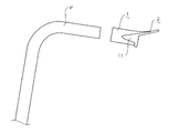
即ち、本考案は、歯科診療に用いる口内吸引装置における吸引パイプPの先端部分に着脱自在に挿着可能な軟質樹脂材料から成る円筒状のアタッチメント部材であって、
本体円筒部1における一方の開口端部には、嘴形の吸引口2を一体に突成し、かつ、この本体円筒部1の外周面における前記吸引口2の基端部近傍には凸部11を突成して、
この凸部11に指を引っ掛けて、前記吸引パイプPに挿着した状態における前記本体円筒部1を回転容易に構成するという技術的手段を採用した。
That is, the present invention is a cylindrical attachment member made of a soft resin material that can be detachably inserted into the distal end portion of the suction pipe P in an intraoral suction device used for dental practice,
A saddle-shaped suction port 2 is integrally formed at one opening end of the main body cylindrical portion 1, and a convex portion is formed in the vicinity of the base end portion of the suction port 2 on the outer peripheral surface of the main body cylindrical portion 1. 11
A technical means is adopted in which the main body cylindrical portion 1 is configured to be easily rotated by hooking a finger on the
また、本考案は、上記課題を解決するために、必要に応じて上記手段に加え、本体円筒部1の凸部11を軸方向に沿ってリブ状に成形するという技術的手段を採用した。
Moreover, in order to solve the said subject, this invention employ | adopted the technical means of shape | molding the
更にまた、本考案は、上記課題を解決するために、必要に応じて上記手段に加え、本体円筒部1の凸部11を、外周面における対向位置に対称的にそれぞれ突成するという技術的手段を採用した。
Furthermore, in order to solve the above-described problems, the present invention is technically configured to project the
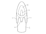
更にまた、本考案は、上記課題を解決するために、必要に応じて上記手段に加え、嘴形の吸引口2の内側面から本体円筒部1の内側面に連通する長手方向に亙り肉厚部21を成形して、前記吸引口2に弾力的な剛りを付与するという技術的手段を採用した。
Furthermore, in order to solve the above-mentioned problems, the present invention extends over the longitudinal direction communicating from the inner surface of the bowl-shaped suction port 2 to the inner surface of the main body cylindrical portion 1 in addition to the above means as necessary. The technical means of forming the
更にまた、本考案は、上記課題を解決するために、必要に応じて上記手段に加え、本体円筒部1および吸引口2を、シリコーンゴムで作製するという技術的手段を採用した。 Furthermore, in order to solve the above-described problems, the present invention employs technical means in which the main body cylindrical portion 1 and the suction port 2 are made of silicone rubber in addition to the above-described means as necessary.
本考案は、歯科診療に用いる口内吸引装置における吸引パイプの先端部分に着脱自在に挿着可能な軟質樹脂材料から成る円筒状のアタッチメント部材において、本体円筒部における一方の開口端部には、嘴形の吸引口を一体に突成して、かつ、この本体円筒部の外周面における前記吸引口の基端部近傍には凸部を突成したことによって、この凸部に指を引っ掛けて、前記吸引パイプに挿着した状態における前記本体円筒部を容易に回わすことができる。 The present invention relates to a cylindrical attachment member made of a soft resin material that can be detachably inserted into a distal end portion of a suction pipe in an intraoral suction device used for dental practice. By projecting a suction port of the shape integrally and projecting a convex portion in the vicinity of the base end portion of the suction port on the outer peripheral surface of the main body cylindrical portion, a finger is hooked on the convex portion, The main body cylindrical portion in a state of being inserted into the suction pipe can be easily turned.
したがって、本考案の歯科診療用バキュームチップを使用することにより、口腔内において吸引箇所を移動する際にチップを回わす必要がある場合であっても、チップ表面が滑り難くて、しかも、迅速・確実に回わすことができることから、歯科診療用バキュームチップとしての実用的利用価値は頗る高いと云える。 Therefore, by using the dental care vacuum tip of the present invention, even when the tip needs to be rotated when moving the suction site in the oral cavity, the tip surface is difficult to slip, and Since it can be reliably rotated, it can be said that the practical use value as a dental medical vacuum chip is very high.
本考案を実施するための最良の形態を具体的に図示した図面に基づいて更に詳細に説明すると、次のとおりである。 BEST MODE FOR CARRYING OUT THE INVENTION The best mode for carrying out the present invention will be described in more detail with reference to the drawings specifically shown as follows.
本考案の実施形態を図1から図6に基づいて説明する。図中、符号1で指示するものは本体円筒部であり、符号2で指示するものは吸引口である。 An embodiment of the present invention will be described with reference to FIGS. In the figure, what is indicated by reference numeral 1 is a cylindrical body, and what is indicated by reference numeral 2 is a suction port.
しかして、本考案は、歯科診療に用いる吸引装置における吸引パイプPの先端部分に着脱自在に挿着可能な軟質樹脂から成る円筒状のアタッチメント部材であって、構成するにあっては、まず、本体円筒部1における一方の開口端部には、嘴形の吸引口2を一体に突成する(図1および図2参照)。 Thus, the present invention is a cylindrical attachment member made of a soft resin that can be detachably inserted into the distal end portion of the suction pipe P in the suction device used for dental practice. A bowl-shaped suction port 2 is integrally formed at one opening end of the main body cylindrical portion 1 (see FIGS. 1 and 2).
本実施形態では、本体円筒部1および吸引口2の使用材料を、軟質樹脂であるシリコーンゴムにすることができ、ホットプレス成形により作製する。このシリコーンゴムは、適度な柔軟性およびタック性を有しており、口腔内での当たりが良く、かつ、吸引パイプPの端部外周面に密着して気密性も高めることができる。 In this embodiment, the material used for the main body cylindrical portion 1 and the suction port 2 can be made of silicone rubber, which is a soft resin, and is manufactured by hot press molding. This silicone rubber has moderate flexibility and tackiness, is good in the oral cavity, and can be tightly adhered to the outer peripheral surface of the end of the suction pipe P to improve airtightness.
また、この本体円筒部1の外周面における前記吸引口2の基端部近傍には凸部11を突成する。本実施形態では、本体円筒部1の凸部11を軸方向に沿ってリブ状に成形することによって、回転方向に対して直交する方向となり、指を引っ掛け易くすることができる。
Further, a
また、本実施形態では、本体円筒部1の凸部11を、外周面における対向位置に対称的にそれぞれ突成することによって、指で摘んだときの引っ掛かりを良くして、良好な回転操作性を得ることができる。
Moreover, in this embodiment, the
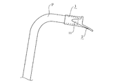
そして、図3に示すように、本体円筒部1を吸引パイプPの先端部分に挿着し、この凸部11に指を引っ掛けて、当該吸引パイプPに挿着した状態における前記本体円筒部1を回わし易くすることができる(図4および図5参照)。
Then, as shown in FIG. 3, the main body cylindrical portion 1 in a state where the main body cylindrical portion 1 is inserted into the tip portion of the suction pipe P, a finger is hooked on the
本考案は、概ね上記のように構成されるが、本考案は図示の実施形態に限定されるものでは決してなく、「実用新案登録請求の範囲」の記載内において種々の変更が可能であって、例えば、本体円筒部1の凸部11の形状は、リブ状に限らず、円形などの隆起状、突起状のものであっても良く、また、数量も外周面において任意に成形することができる。
The present invention is generally configured as described above. However, the present invention is not limited to the illustrated embodiment, and various modifications can be made within the description of “the scope of claims for utility model registration”. For example, the shape of the
また、図6に示すように、嘴形の吸引口2の内側面から本体円筒部1の内側面に連通する長手方向に亙り肉厚部21を成形して、前記吸引口2に弾力的な剛りを付与することができ、口腔内で吸引作業している際に、舌や粘膜に吸着してしまうのを効果的に防止することもでき、これら何れのものも本考案の技術的範囲に属する。
Further, as shown in FIG. 6, a
1 本体円筒部
11 凸部
2 吸引口
21 肉厚部
P 吸引パイプ
1 Body cylinder
11 Convex part 2 Suction port
21 Thick part P Suction pipe
Claims (5)
本体円筒部1における一方の開口端部には、嘴形の吸引口2が一体に突成されており、かつ、この本体円筒部1の外周面における前記吸引口2の基端部近傍には凸部11が突成されており、
この凸部11に指を引っ掛けて、前記吸引パイプPに挿着した状態における前記本体円筒部1を回転容易に構成したことを特徴とする歯科診療用バキュームチップ。 A cylindrical attachment member made of a soft resin material that can be detachably attached to a tip portion of a suction pipe P in an intraoral suction device used for dental practice,
A bowl-shaped suction port 2 is integrally formed at one opening end of the main body cylindrical portion 1, and in the vicinity of the base end portion of the suction port 2 on the outer peripheral surface of the main body cylindrical portion 1. Convex part 11 is formed,
A vacuum tip for dental practice characterized in that the main body cylindrical portion 1 in a state where the finger 11 is hooked on the convex portion 11 and is inserted into the suction pipe P is easily rotated.
Publications (1)
| Publication Number | Publication Date |
|---|---|
| JP3147635U true JP3147635U (en) | 2009-01-15 |
Family
ID=
Cited By (1)
| Publication number | Priority date | Publication date | Assignee | Title |
|---|---|---|---|---|
| JP2014524804A (en) * | 2011-07-08 | 2014-09-25 | エルゴメディ オサケ ユキチュア | Equipment related to oral and dental care |
Cited By (2)
| Publication number | Priority date | Publication date | Assignee | Title |
|---|---|---|---|---|
| JP2014524804A (en) * | 2011-07-08 | 2014-09-25 | エルゴメディ オサケ ユキチュア | Equipment related to oral and dental care |
| US9486563B2 (en) | 2011-07-08 | 2016-11-08 | Gunilla Taddeo | Instrument in connection with oral and dental care |
Similar Documents
| Publication | Publication Date | Title |
|---|---|---|
| US20070113844A1 (en) | Endoscopic bite block | |
| US7934505B2 (en) | Endoscopic bite block | |
| JP2017518859A (en) | Intraoral device and method of use thereof | |
| KR102061779B1 (en) | Liquid suction device | |
| US20210259817A1 (en) | Suction tip | |
| JP2006246916A (en) | Odontotherapy suction chip | |
| EP3716864A1 (en) | Retractor and tip extender therefor | |
| US7238023B1 (en) | Saliva ejector or eductor | |
| JP3147635U (en) | Dental treatment vacuum tip | |
| KR102286241B1 (en) | Easily removable medical gag and suction device | |
| KR101522314B1 (en) | Mouth prop for suction | |
| CN104436397A (en) | Anti-biting pad used in oral cavity intubation tube | |
| CN107928812B (en) | Root canal file holder | |
| JP3214276U (en) | Oral endoscope mouthpiece | |
| CN205626147U (en) | Can fix dam facebow of inhaling salivary duct | |
| CN111265322B (en) | Dual-purpose saliva aspirator capable of preventing bone meal inhalation | |
| JP2007319530A (en) | Periodontal pocket cleaning terminal and periodontal disease treatment apparatus | |
| CN209770571U (en) | Saliva support device in mouth | |
| US9456880B1 (en) | Dental wedge with a flexible tubing suction line | |
| JP2004321710A (en) | Elastic suction chip used for suction machine | |
| CN204428578U (en) | The pervasive bite-block of a kind of oral intubation | |
| CN204428577U (en) | The anti-bite bite-block used in a kind of oral intubation | |
| JP2005013394A (en) | Point chip for liquid suction device | |
| CN216257487U (en) | Eraser fixing clamp | |
| CN205612568U (en) | Easily fix dam facebow of inhaling salivary duct |