JP3147157U - Driver bit - Google Patents
Driver bit Download PDFInfo
- Publication number
- JP3147157U JP3147157U JP2008006992U JP2008006992U JP3147157U JP 3147157 U JP3147157 U JP 3147157U JP 2008006992 U JP2008006992 U JP 2008006992U JP 2008006992 U JP2008006992 U JP 2008006992U JP 3147157 U JP3147157 U JP 3147157U
- Authority
- JP
- Japan
- Prior art keywords
- driver bit
- cone
- edge portion
- screw member
- blade edge
- Prior art date
- Legal status (The legal status is an assumption and is not a legal conclusion. Google has not performed a legal analysis and makes no representation as to the accuracy of the status listed.)
- Expired - Fee Related
Links
Images


Classifications
-
- B—PERFORMING OPERATIONS; TRANSPORTING
- B25—HAND TOOLS; PORTABLE POWER-DRIVEN TOOLS; MANIPULATORS
- B25B—TOOLS OR BENCH DEVICES NOT OTHERWISE PROVIDED FOR, FOR FASTENING, CONNECTING, DISENGAGING OR HOLDING
- B25B15/00—Screwdrivers
- B25B15/001—Screwdrivers characterised by material or shape of the tool bit
- B25B15/002—Screwdrivers characterised by material or shape of the tool bit characterised by material used or surface finishing
Abstract
【課題】ドライバービットの一端に取付けた刃先部からなるドライバービットを提供する。
【解決手段】刃先部21は2つ以上の係合面24を有し、各係合面24には多数の錐体突起26を設け、且つ各錐体突起26は等間隔で各係合面24上に規則的に配列し、各錐体突起26先端にはそれぞれ当接点28を形成し、各錐体突起26の当接点28は同一平面上に位置する。また、連結部31はドライバービット11の他端に取付けてドライバーハンドルに接合する。そしてユーザーが刃先部21で螺子部材を締着すると、刃先部21上の各錐体突起26の当接点は螺子部材との間で全面的に咬み合って、摩擦力を高め受力が平均となる効果を果たす。
【選択図】図1A driver bit comprising a cutting edge portion attached to one end of a driver bit is provided.
A cutting edge portion has two or more engaging surfaces, and each engaging surface is provided with a large number of cone projections, and each cone projection is arranged at equal intervals. 24. The contact points 28 are formed at the tips of the cone projections 26, and the contact points 28 of the cone projections 26 are located on the same plane. The connecting portion 31 is attached to the other end of the driver bit 11 and joined to the driver handle. Then, when the user fastens the screw member with the blade edge portion 21, the contact point of each cone projection 26 on the blade edge portion 21 is completely engaged with the screw member, and the friction force is increased and the receiving force is averaged. Fulfills the effect.
[Selection] Figure 1
Description
本考案はハンドツールのスクリュードライバーに関し、特にドライバービットに関する。 The present invention relates to a screwdriver for a hand tool, and more particularly to a driver bit.
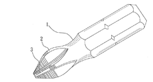
従来のスクリュードライバーのビットの刃先部はいずれも平滑な表面設計であるため、螺子部材を締めたり緩めたりする際にドライバービットと螺子部材との間の摩擦力が不十分なことから滑動するという状況がよく起こり、その使用効果に影響を及ぼしている。そこで上記の欠点を改善するために、図5で示すドライバービットの改良設計が知られている。図5によると、ドライバービット1の刃先部2に若干の横の紋様部3を設計して、ドライバービット1と螺子部材との間の摩擦力を高めているものの、使用面において横の紋様方式の設計で生じた滑り止め効果には限界があり、なお理想的とは言い難い。
Since the cutting edge portion of the conventional screwdriver bit has a smooth surface design, when the screw member is tightened or loosened, the friction force between the driver bit and the screw member is insufficient, so that it slides. The situation is common and affects its effectiveness. In order to improve the above-described drawbacks, an improved design of the driver bit shown in FIG. 5 is known. According to FIG. 5, although a slight horizontal pattern 3 is designed on the
このため、図6で示すように、ドライバービット1の刃先部2に不規則な方法で若干の滑り止め粒4を取り付けることによって、ドライバービット1と螺子部材との間の摩擦力を高めた業者がいるが、こうした滑り止め粒4の設計では、ダイヤモンド粉を直接ドライバービット1の刃先部2に吹き付けても、一体鍛造の方法で製造しても、使用面で受力が不均等となる状況が起こり得る。図7で示すように、滑り止め粒4は不規則な方法でドライバービット1の刃先部2に取り付けられている。また、滑り止め粒4のサイズも各々異なるため、滑り止め粒4は螺子部材5の間で完全な咬み合せの状態に至らず、大き目の滑り止め粒4では使用面における受力が大きくなり破損する状況が起き易い。
For this reason, as shown in FIG. 6, a trader who increases the frictional force between the
本考案の主な目的は、ドライバービットで螺子部材を互いに接合する際に、摩擦力を高め受力を平均とすることが可能なドライバービットを提供することにある。 A main object of the present invention is to provide a driver bit that can increase frictional force and average receiving force when screw members are joined to each other with the driver bit.
前記の目的を達するため、本考案は、刃先部と連結部を有し、刃先部をドライバービットの一端に取り付け、刃先部は2つ以上の係合面を有し、各係合面に多数の錐体突起が等間隔で規則的に配列し、各錐体突起の先端はそれぞれ当接点を形成し、各錐体突起の当接点は同一平面上に位置し、連結部はドライバービットの他端に設けられてドライバーハンドルに接合することを特徴とするドライバービットの改良構造を提供する。 In order to achieve the above object, the present invention has a cutting edge portion and a connecting portion, the cutting edge portion is attached to one end of a driver bit, the cutting edge portion has two or more engaging surfaces, and each engaging surface has a large number. The cone projections are regularly arranged at equal intervals, the tips of the cone projections form contact points, the contact points of the cone projections are on the same plane, Provided is an improved structure of a driver bit which is provided at an end and is joined to a driver handle.
(考案の効果)
ユーザーが刃先部で螺子部材を締着すると、刃先部上の各錐体突起の当接点は螺子部材との間で全面的に咬み合って、摩擦力を高め受力が平均となる効果を果たすことができる。
(Effect of device)
When the user fastens the screw member at the blade edge portion, the contact point of each cone projection on the blade edge portion is completely engaged with the screw member, and the frictional force is increased and the receiving force is averaged. be able to.
(第1実施例)
まず図1は本考案が提供するドライバービット11の改良構造を示しており、主に刃先部21と連結部31から構成される。刃先部21をドライバービット11の一端に取り付け、ドライバービット11は十字形のドライバーであって、刃先部21は4片の係合壁22で構成され、8面の係合面24を有する。各係合面24上にはサイズと形が同様の多数の錐体突起26を取り付け、各錐体突起26は等間隔で各係合面24上に規則的に配列し、各錐体突起26の先端はそれぞれ当接点28を形成し、各錐体突起26の当接点28は、図3に示すように同一平面51上に位置する。連結部31はドライバービット11の他端に設けられ、連結部31は六角柱の形状で、ドライバーハンドル又はスリーブ(図示せず)と互いに接合する。
(First embodiment)
First, FIG. 1 shows an improved structure of a
図2、図3によると、ユーザーが刃先部21と螺子部材41とを互いに接合させて締めたり緩めたりの動作を行う際、刃先部21上の錐体突起26が等間隔で配列され且つそのサイズと形が同様であり、各錐体突起26の当接点28が同一平面51上に位置することで、螺子部材41と接合する際、各錐体突起26の当接点28は螺子部材41との間で全面的に咬み合う状態となり、摩擦力を高めることができるだけでなく、使用時に受力が平均となる効果も達せられ、本考案のドライバービット11の使用効果が高められる。
According to FIGS. 2 and 3, when the user performs the operations of fastening and loosening the
(第2実施例)
図4は本考案の第2実施例である。ドライバービット11aは一の字型ドライバービットで、刃先部21aは1片の係合壁22aで構成され、2面の係合面24aを有し、2面の係合面24a上には同様に、サイズと形が同じの複数の錐体突起26aを取り付け、各錐体突起26aもまた等間隔で2面の係合面上に規則的に配列し、各錐体突起26aの先端に形成した当接点28aもまた同一平面51a上に位置することで、一の字型ドライバービット11aも摩擦力を高め、使用時に受力を平均にする効果が果たせられる。
(Second embodiment)
FIG. 4 shows a second embodiment of the present invention. The
また、各錐体突起26は三角錐又は四角錐形状の多角形の錐体状の造形でもよい旨ここで特に説明しておく。
It will be particularly described here that each of the
上記の構造設計により、本考案には下記の長所がある。
1.本考案は錐体突起の設計によって螺子部材との間の摩擦力を高めることができると共に、滑り止め効果を高めることができる。
2.本考案の錐体突起は等間隔で各係合面上に規則的に配列し、螺子部材と互いに接合する際、錐体突起の当接点は螺子部材と全面的に咬み合って、使用の際に受力が平均となる効果を達することができ、ドライバービットの使用効果を高めることができる。
3.本考案の錐体突起を使用する際、各錐体突起の受力がいずれも同様なことから破損し難く、ドライバービットの耐用年数を延ばすことができる。
Due to the above structural design, the present invention has the following advantages.
1. The present invention can increase the frictional force between the screw member and the anti-slip effect by designing the cone projection.
2. The cone projections of the present invention are regularly arranged on the respective engagement surfaces at equal intervals, and when they are joined to the screw members, the contact points of the cone projections are completely engaged with the screw members for use. Therefore, it is possible to achieve an effect that the receiving force becomes an average, and the use effect of the driver bit can be enhanced.
3. When the cone projections of the present invention are used, since the receiving force of each cone projection is the same, it is difficult to break, and the service life of the driver bit can be extended.
上述したように、本考案において摩擦力を高め、使用時に受力を平均にする効果を有し、ドライバービットの使用効果を高めて耐用年数を延ばすことができることは、実用新案法の規定に合致し、よって法に則り実用新案登録許願するものとする。 As described above, the present invention has the effect of increasing the frictional force and averaging the receiving force during use, and the fact that the usefulness of the driver bit can be increased and the service life can be extended, conforms to the provisions of the Utility Model Law. Therefore, in accordance with the law, a utility model registration application shall be granted.
11:ドライバービット、21:刃先部、22:係合壁、24:係合面、26:錐体突起、28:当接点、31:連結部、41:螺子部材、51:平面 DESCRIPTION OF SYMBOLS 11: Driver bit, 21: Cutting edge part, 22: Engagement wall, 24: Engagement surface, 26: Conical protrusion, 28: Contact point, 31: Connection part, 41: Screw member, 51: Plane
Claims (2)
前記ドライバービットの他端に取付けられてドライバーハンドルに接合する連結部と、を備え、
前記刃先部で螺子部材を締着する際に、前記刃先部の各錐体突起の当接点が前記螺子部材との間で全面的に咬み合い、摩擦力を高め受力が平均となるように作用することを特徴とするドライバービット。 A blade edge portion attached to one end of a driver bit, having two or more engaging surfaces, and a plurality of cone projections regularly arranged at regular intervals on each of the engagement surfaces. A cutting edge portion arranged and attached so that the contact points to be formed are located on the same plane;
A connecting portion attached to the other end of the driver bit and joined to the driver handle,
When the screw member is fastened by the blade edge part, the contact point of each cone projection of the blade edge part is completely engaged with the screw member so that the frictional force is increased and the receiving force is averaged. Driver bit characterized by acting.
Applications Claiming Priority (1)
| Application Number | Priority Date | Filing Date | Title |
|---|---|---|---|
| TW096137523A TW200916277A (en) | 2007-10-05 | 2007-10-05 | Improved structure of screwdriver bit |
Publications (1)
| Publication Number | Publication Date |
|---|---|
| JP3147157U true JP3147157U (en) | 2008-12-18 |
Family
ID=40149800
Family Applications (1)
| Application Number | Title | Priority Date | Filing Date |
|---|---|---|---|
| JP2008006992U Expired - Fee Related JP3147157U (en) | 2007-10-05 | 2008-10-06 | Driver bit |
Country Status (4)
| Country | Link |
|---|---|
| US (1) | US20100288086A1 (en) |
| EP (1) | EP2045042A3 (en) |
| JP (1) | JP3147157U (en) |
| TW (1) | TW200916277A (en) |
Families Citing this family (14)
| Publication number | Priority date | Publication date | Assignee | Title |
|---|---|---|---|---|
| US8418587B2 (en) | 2008-11-07 | 2013-04-16 | Milwaukee Electric Tool Corporation | Tool bit |
| TW201103708A (en) * | 2009-07-31 | 2011-02-01 | Yu-Jun Li | Improved screwdriver |
| USD711719S1 (en) | 2009-11-06 | 2014-08-26 | Milwaukee Electric Tool Corporation | Tool bit |
| TW201309431A (en) * | 2011-08-16 | 2013-03-01 | Meeng Gang Entpr Co Ltd | Fabrication method of screwdriver bit |
| US8770070B2 (en) * | 2012-04-23 | 2014-07-08 | Tsai-Fa Liu | Universal anti-torque screwdriver head structure |
| US8955418B2 (en) | 2013-03-08 | 2015-02-17 | Black & Decker Inc. | Threaded fastener driving tool |
| US10022845B2 (en) | 2014-01-16 | 2018-07-17 | Milwaukee Electric Tool Corporation | Tool bit |
| USD862193S1 (en) * | 2017-02-10 | 2019-10-08 | Wiha Werkzeuge Gmbh | Screwdriver bit |
| US11059162B2 (en) | 2017-05-17 | 2021-07-13 | Milwaukee Electric Tool Corporation | Screwdriver |
| USD855433S1 (en) | 2017-08-09 | 2019-08-06 | Milwaukee Electric Tool Corporation | Screwdriver |
| CN212351801U (en) | 2017-12-01 | 2021-01-15 | 米沃奇电动工具公司 | Tool head for driving fasteners |
| USD921468S1 (en) | 2018-08-10 | 2021-06-08 | Milwaukee Electric Tool Corporation | Driver bit |
| USD985349S1 (en) * | 2021-05-07 | 2023-05-09 | Hermann Frühm | Screwdriver bit |
| TWI784842B (en) * | 2021-12-15 | 2022-11-21 | 洪昭敏 | screwdriver head structure |
Family Cites Families (9)
| Publication number | Priority date | Publication date | Assignee | Title |
|---|---|---|---|---|
| FR685851A (en) * | 1929-11-30 | 1930-07-18 | Bridgeport Hardware Mfg Corp | Screwdriver enhancements |
| US1899489A (en) * | 1931-10-02 | 1933-02-28 | Wickbergh Godfrey | Screw driver |
| US3133568A (en) * | 1962-04-02 | 1964-05-19 | Reed & Prince Mfg Company | Bit end of tool for driving screw fastener |
| US3616827A (en) * | 1969-08-11 | 1971-11-02 | Gardner Denver Co | Non-magnetic fastener pick-up and driving tool |
| US4778730A (en) * | 1987-09-09 | 1988-10-18 | Remgrit Corporation | Method of applying non-slip coating to tools and resulting product |
| EP0675783A1 (en) * | 1992-12-22 | 1995-10-11 | WERA WERK HERMANN WERNER GMBH & CO. | Tool, in particular a screwdriver bit |
| DE19720139C1 (en) * | 1997-05-14 | 1999-03-18 | Hahn Willi Gmbh | Screwdriver fastener drive tip |
| US6223634B1 (en) * | 1997-10-03 | 2001-05-01 | Phillips Screw Company | Recessed head fastener and driver systems |
| MY127032A (en) * | 1999-12-28 | 2006-11-30 | Hitachi Metals Ltd | Work chamfering apparatus and work chamfering method |
-
2007
- 2007-10-05 TW TW096137523A patent/TW200916277A/en not_active IP Right Cessation
-
2008
- 2008-09-15 EP EP08016248A patent/EP2045042A3/en not_active Withdrawn
- 2008-09-18 US US12/233,090 patent/US20100288086A1/en not_active Abandoned
- 2008-10-06 JP JP2008006992U patent/JP3147157U/en not_active Expired - Fee Related
Also Published As
| Publication number | Publication date |
|---|---|
| TW200916277A (en) | 2009-04-16 |
| EP2045042A3 (en) | 2009-09-23 |
| EP2045042A2 (en) | 2009-04-08 |
| US20100288086A1 (en) | 2010-11-18 |
| TWI327094B (en) | 2010-07-11 |
Similar Documents
| Publication | Publication Date | Title |
|---|---|---|
| JP3147157U (en) | Driver bit | |
| US20080006126A1 (en) | Hexagonal bolt head and hexagonal recess of socket | |
| JP2020508887A (en) | Multi grip socket bit | |
| TWM466982U (en) | Screw | |
| TWI742234B (en) | Spherical anti-slip fastener remover | |
| TWI674951B (en) | Tool head with groove for removal from lug | |
| TWI701108B (en) | Multi-grip socket bit | |
| JP5500719B2 (en) | Nut with washer | |
| JP3186028U (en) | Tool head structure | |
| KR101769251B1 (en) | Hexagonal Wrench Assembly | |
| JP3234637U (en) | Hook spanner | |
| JP3171573U (en) | Special recess screw to prevent tampering | |
| JP5936022B1 (en) | P cone fitting | |
| JP5893906B2 (en) | Nailing tool | |
| WO2010000204A1 (en) | A fastener provided with fastening teeth and a special wrench thereof | |
| JP3170020U (en) | Non-slip tool | |
| JP3101538U (en) | Improved nut | |
| JP3160250U (en) | wrench | |
| JP3194964U (en) | toothbrush | |
| CN204692290U (en) | A kind of high-performance hexagon weld nut | |
| JP3182674U (en) | wrench | |
| JP2002364619A (en) | Screw part and screw part tightening tool | |
| JP2006130633A (en) | Multi-function hand tool | |
| JP3177052U (en) | Star wrench structure | |
| CN202742341U (en) | Hammer with firmly-connected hammer head |
Legal Events
| Date | Code | Title | Description |
|---|---|---|---|
| R150 | Certificate of patent or registration of utility model |
Free format text: JAPANESE INTERMEDIATE CODE: R150 |
|
| FPAY | Renewal fee payment (event date is renewal date of database) |
Free format text: PAYMENT UNTIL: 20111126 Year of fee payment: 3 |
|
| FPAY | Renewal fee payment (event date is renewal date of database) |
Free format text: PAYMENT UNTIL: 20121126 Year of fee payment: 4 |
|
| FPAY | Renewal fee payment (event date is renewal date of database) |
Free format text: PAYMENT UNTIL: 20131126 Year of fee payment: 5 |
|
| R250 | Receipt of annual fees |
Free format text: JAPANESE INTERMEDIATE CODE: R250 |
|
| LAPS | Cancellation because of no payment of annual fees |