JP3144887U - Squeegee polishing equipment - Google Patents
Squeegee polishing equipment Download PDFInfo
- Publication number
- JP3144887U JP3144887U JP2008004586U JP2008004586U JP3144887U JP 3144887 U JP3144887 U JP 3144887U JP 2008004586 U JP2008004586 U JP 2008004586U JP 2008004586 U JP2008004586 U JP 2008004586U JP 3144887 U JP3144887 U JP 3144887U
- Authority
- JP
- Japan
- Prior art keywords
- squeegee
- polishing
- belt
- reciprocating
- abrasive
- Prior art date
- Legal status (The legal status is an assumption and is not a legal conclusion. Google has not performed a legal analysis and makes no representation as to the accuracy of the status listed.)
- Expired - Fee Related
Links
Images


Abstract
【課題】スクリーン印刷用のスキージの先端部を、変形を防止しながら平滑に研磨して断面円弧状とするスキージ研磨装置を提供する。
【解決手段】スキージ11の先端部を研磨するスキージ研磨装置10において、研磨ベルト14を備えたベルト研磨機構15と、研磨ベルト14の研磨面の上流側に研磨材ブロック16を当接させ、研磨材ブロック16を研磨ベルト14の幅方向全体に渡って往復移動させて研磨材ブロック16を研削し、発生した研磨材粉を研磨ベルト14の幅方向全体に付着させる研磨粉付着手段17と、スキージ11の先端部を研磨材粉が付着した研磨ベルト14に載せて、スキージ11を断面円弧状とした先端部の曲率半径の中心を基準として回動させるスキージ保持手段18と、スキージ保持手段18を研磨ベルト14の幅方向に往復移動する往復移動手段19と、スキージ保持手段18を研磨ベルト14に対して昇降する高さ調整手段とを有する。
【選択図】図1A squeegee polishing apparatus is provided which smoothly polishes the tip of a screen printing squeegee while preventing deformation, thereby obtaining a circular arc cross section.
In a squeegee polishing apparatus 10 for polishing a tip portion of a squeegee 11, a belt polishing mechanism 15 including a polishing belt 14 and an abrasive block 16 are brought into contact with an upstream side of a polishing surface of the polishing belt 14 to polish the squeegee. Abrasive powder adhering means 17 for reciprocating the material block 16 over the entire width direction of the polishing belt 14 to grind the abrasive block 16 and adhering the generated abrasive powder to the entire width direction of the polishing belt 14, and a squeegee. The squeegee holding means 18 is mounted on the polishing belt 14 to which abrasive powder is adhered, and the squeegee 11 is rotated with reference to the center of the radius of curvature of the tip having an arcuate cross section. A reciprocating means 19 that reciprocates in the width direction of the polishing belt 14 and a height adjusting means that moves the squeegee holding means 18 up and down relative to the polishing belt 14 are provided.
[Selection] Figure 1
Description
本考案は、スクリーン印刷用のスキージの先端部を研磨して断面円弧状とする(丸める)スキージ研磨装置に関する。 The present invention relates to a squeegee polishing apparatus that polishes (rounds) a tip of a squeegee for screen printing into a circular arc shape in cross section.
スクリーン印刷では、被印刷物表面の上方に配置され、印刷しようとするパターンが形成されたスクリーン上にペーストを塗布し、スキージの先端部をスクリーン上に当接させて移動することにより、被印刷物表面にペーストを付着させている。ここで、スキージの先端部を断面円弧状とする整形は、回転する砥石でスキージの先端部を研磨して行っている(例えば、特許文献1参照)。 In screen printing, a paste is applied on a screen placed above the surface of the substrate to be printed, and the surface of the substrate is moved by moving the tip of the squeegee in contact with the screen. The paste is attached to the. Here, shaping the tip of the squeegee to have a circular arc shape is performed by polishing the tip of the squeegee with a rotating grindstone (see, for example, Patent Document 1).
ここで、スキージは、例えば、ポリウレタン樹脂(ポリウレタンゴム)等の弾力性を有する材質で形成されているため、特許文献1に記載されたようにスキージの先端部に砥石を直接接触させて研磨しながら整形を行うと、整形部には微細な凹凸が発生すると共に、研磨時の摩擦熱で整形部に変形が生じるという問題がある。
Here, since the squeegee is formed of a material having elasticity such as polyurethane resin (polyurethane rubber), for example, as described in
本考案はかかる事情に鑑みてなされたもので、スクリーン印刷用のスキージの先端部の変形を防止しながら平滑に(表面に凹凸がなく滑らかに)研磨して断面円弧状とすることが可能なスキージ研磨装置を提供することを目的とする。 The present invention has been made in view of such circumstances, and can be smoothly polished (smoothly without any irregularities on the surface) to have a circular arc shape while preventing deformation of the tip of a screen printing squeegee. An object of the present invention is to provide a squeegee polishing apparatus.
前記目的に沿う本考案に係るスキージ研磨装置は、スクリーン印刷用のスキージのスクリーンに当接して移動する先端部を研磨して断面円弧状とするスキージ研磨装置において、
駆動ロール及びガイドロール間に水平に架け渡された研磨ベルトを備えたベルト研磨機構と、
前記研磨ベルトの研磨面の上流側に研磨材ブロックを当接させ、該研磨材ブロックを該研磨ベルトの幅方向全体に渡って往復移動させて該研磨材ブロックを研削し、発生した研磨材粉を該研磨ベルトの幅方向全体に渡って付着させる研磨粉付着手段と、
前記スキージの先端部を前記研磨材粉が付着した前記研磨ベルトの研磨面に載せて、断面円弧状とした前記先端部の曲率半径の中心を基準として、前記スキージを回動させるスキージ保持手段と、
前記スキージ保持手段を前記研磨ベルトの幅方向に往復移動する往復移動手段と、
前記往復移動手段を介して前記スキージ保持手段を前記研磨ベルトの研磨面に対して昇降する高さ調整手段とを有している。
A squeegee polishing apparatus according to the present invention that meets the above-described object is a squeegee polishing apparatus that polishes a tip portion that moves in contact with a screen of a squeegee for screen printing to have a circular arc shape in cross section.
A belt polishing mechanism including a polishing belt horizontally stretched between a drive roll and a guide roll;
Abrasive powder is generated by bringing an abrasive block into contact with the upstream side of the polishing surface of the abrasive belt, grinding the abrasive block by reciprocating the abrasive block across the entire width of the abrasive belt, Polishing powder adhering means for adhering the entire width of the polishing belt,
Squeegee holding means for placing the tip of the squeegee on the polishing surface of the polishing belt to which the abrasive powder is adhered and rotating the squeegee with reference to the center of the radius of curvature of the tip having an arcuate cross section; ,
Reciprocating means for reciprocating the squeegee holding means in the width direction of the polishing belt;
And a height adjusting means for raising and lowering the squeegee holding means with respect to the polishing surface of the polishing belt via the reciprocating means.
本考案に係るスキージ研磨装置において、前記ベルト研磨機構、前記研磨粉付着手段、前記スキージ保持手段、前記往復移動手段、及び前記高さ調整手段は基台に支持され、該基台には、開閉扉を備え該ベルト研磨機構、該研磨粉付着手段、該スキージ保持手段、該往復移動手段、及び該高さ調整手段を一体で覆うカバー部材が取付けられていることが好ましい。 In the squeegee polishing apparatus according to the present invention, the belt polishing mechanism, the abrasive powder adhering means, the squeegee holding means, the reciprocating means, and the height adjusting means are supported by a base, and the base is opened and closed. It is preferable that a cover member including a door and integrally covering the belt polishing mechanism, the polishing powder adhering unit, the squeegee holding unit, the reciprocating unit, and the height adjusting unit is attached.
本考案に係るスキージ研磨装置において、前記研磨材ブロックはガラスブロックとすることができる。 In the squeegee polishing apparatus according to the present invention, the abrasive block may be a glass block.
本考案に係るスキージ研磨装置においては、スキージの先端部を研磨材粉が付着した研磨ベルトの研磨面に当接させるので、スキージの先端部が研磨材粉で研磨されることになって、スキージの先端部を平滑に整形することができると共に、研磨材粉が潤滑材としても作用することで摩擦熱の発生を抑えて、スキージの先端部が熱で変形するのを防止できる。ここで、研磨粉付着手段は研磨材ブロックを研磨ベルトの幅方向全体に渡って往復移動させるので、研磨ベルトが部分的に損耗するのが防止でき、スキージの研磨精度の低下を防止することができると共に、研磨ベルトの寿命を延長することができる。そして、スキージ保持手段はスキージを研磨ベルトに載せて、断面円弧状とした先端部の曲率半径の中心を基準としてスキージを回動させるので、スキージの先端部を断面円弧状とする整形を自動で行うことができる。また、往復移動手段はスキージ保持手段を研磨ベルトの幅方向に往復移動するので、研磨ベルトの研磨面に付着している研磨材粉を有効に使用してスキージの先端部の研磨を行うことができ、効率的な整形を行うことができる。更に、高さ調整手段は研磨ベルトの研磨面に対するスキージ保持手段の高さ位置を調整するので、スキージの先端部の研磨量を調整でき、研磨後のスキージの先端部の形状精度を向上させることができる。 In the squeegee polishing apparatus according to the present invention, the tip of the squeegee is brought into contact with the polishing surface of the polishing belt to which the abrasive powder has adhered, so that the tip of the squeegee is polished with the abrasive powder. The tip portion of the squeegee can be shaped smoothly, and the abrasive powder also acts as a lubricant, thereby suppressing the generation of frictional heat and preventing the tip portion of the squeegee from being deformed by heat. Here, since the abrasive powder adhering means reciprocates the abrasive block across the entire width of the polishing belt, it is possible to prevent the abrasive belt from being partially worn and to prevent a decrease in the polishing accuracy of the squeegee. In addition, the life of the polishing belt can be extended. And since the squeegee holding means puts the squeegee on the polishing belt and rotates the squeegee with reference to the center of the radius of curvature of the tip having an arcuate cross section, the shaping to make the tip of the squeegee the arcuate cross section is automatically performed. It can be carried out. Further, since the reciprocating means reciprocates the squeegee holding means in the width direction of the polishing belt, the tip of the squeegee can be polished by effectively using the abrasive powder adhering to the polishing surface of the polishing belt. And efficient shaping. Furthermore, since the height adjusting means adjusts the height position of the squeegee holding means with respect to the polishing surface of the polishing belt, the amount of polishing at the tip of the squeegee can be adjusted, and the shape accuracy of the tip of the squeegee after polishing can be improved. Can do.
本考案に係るスキージ研磨装置において、ベルト研磨機構、研磨粉付着手段、スキージ保持手段、往復移動手段、及び高さ調整手段を支持する基台にカバー部材が取付けられている場合、研磨材粉の飛散、スキージの研磨粉の飛散を防止できる。そして、カバー部材には開閉扉が設けられているので、研磨材ブロック及びスキージの取付け、取外しが容易にできると共に、ベルト研磨機構、研磨粉付着手段、スキージ保持手段、往復移動手段、及び高さ調整手段の調整も容易となる。 In the squeegee polishing apparatus according to the present invention, when the cover member is attached to the base supporting the belt polishing mechanism, the abrasive powder adhering means, the squeegee holding means, the reciprocating means, and the height adjusting means, It is possible to prevent scattering and scattering of squeegee polishing powder. Since the cover member is provided with an open / close door, the abrasive block and the squeegee can be easily attached and detached, and the belt polishing mechanism, the abrasive powder adhering means, the squeegee holding means, the reciprocating means, and the height Adjustment of the adjusting means is also facilitated.
本考案に係るスキージ研磨装置において、研磨材ブロックにガラスブロックを使用する場合、ガラスブロックの材質を選択することで研磨材粉の性状を変えることができ、スキージの材質に最適な研磨材粉を選定できる。 In the squeegee polishing apparatus according to the present invention, when a glass block is used for the abrasive block, the properties of the abrasive powder can be changed by selecting the material of the glass block, and the optimum abrasive powder for the squeegee material can be selected. Can be selected.
続いて、添付した図面を参照しつつ、本考案を具体化した実施の形態につき説明し、本考案の理解に供する。
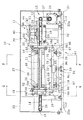
ここで、図1は本考案の一実施の形態に係るスキージ研磨装置の一部省略斜視図、図2は同スキージ研磨装置の一部省略正面図、図3は図2のP−P矢視断面図、図4は図2のQ−Q矢視断面図、図5(A)、(B)は同スキージ研磨装置でスキージの先端部を断面円弧状に研磨する際の状況を示す説明図である。
Next, embodiments of the present invention will be described with reference to the accompanying drawings for understanding of the present invention.
1 is a partially omitted perspective view of a squeegee polishing apparatus according to an embodiment of the present invention, FIG. 2 is a partially omitted front view of the squeegee polishing apparatus, and FIG. 4 is a cross-sectional view taken along the line Q-Q in FIG. 2, and FIGS. 5A and 5B are explanatory views showing a situation when the tip of the squeegee is polished into a circular arc shape with the squeegee polishing apparatus. It is.
図1に示すように、本考案の一実施の形態に係るスキージ研磨装置10は、スクリーン印刷用のスキージ11のスクリーンに当接して移動する先端部を研磨して断面円弧状とする装置であって、駆動ロール12及びガイドロール13間に水平に架け渡された研磨ベルト14を備えたベルト研磨機構15と、研磨ベルト14の研磨面の上流側に研磨材ブロックの一例である直方体状のガラスブロック16を当接させ、ガラスブロック16を研磨ベルト14の幅方向全体に渡って往復移動させてガラスブロック16を研削し、発生した研磨材粉であるガラス粉を研磨ベルト14の幅方向全体に渡って付着させる研磨粉付着手段17と、スキージ11の先端部をガラス粉が付着した研磨ベルト14の研磨面に載せて、スキージ11の断面円弧状とした先端部の曲率半径の中心を基準として、スキージ11を回動させるスキージ保持手段18と、スキージ保持手段18を研磨ベルト14の幅方向に往復移動する往復移動手段19と、往復移動手段19を介してスキージ保持手段18を研磨ベルト14の研磨面に対して昇降する高さ調整手段20とを有している。そして、ベルト研磨機構15、研磨粉付着手段17、スキージ保持手段18、往復移動手段19、及び高さ調整手段20は基台21に支持され、基台21の上部にはベルト研磨機構15、研磨粉付着手段17、スキージ保持手段18、往復移動手段19、及び高さ調整手段20を一体で覆うカバー部材22が、基台21の下部には設置用脚部22aがそれぞれ取付けられ、カバー部材22の正面側中央部には上方に開く開閉扉23が設けられている。以下詳細に説明する。
As shown in FIG. 1, a
ベルト研磨機構(研磨ベルト水平送り機構)15は、基台21の一方側に立設された図示しない駆動ロール支持部材に取付け部材24を介して回転可能に設けられた駆動ロール12と、基台21の他方側に立設されたガイドロール支持部材25に取付け部材26を介して駆動ロール12と同一高さ位置で回転可能に設けられたガイドロール13と、駆動ロール12及びガイドロール13間に水平に架け渡された研磨ベルト14と、駆動ロール支持部材及びガイドロール支持部材25により両端部が水平に支持されて研磨ベルト14の研磨面を水平に保つバックアップ部材14aと、基台21の一方側に取付けられ、動力伝達機能の一例であるベルト27を介して駆動ロール12と連結された回転動力源の一例である電動機28とを有している。
A belt polishing mechanism (abrasive belt horizontal feed mechanism) 15 includes a
研磨粉付着手段17は、ガラスブロック16の上部を収納しその幅方向両側を押圧して把持するブロック保持部材29と、ガラスブロック16の長手方向が研磨ベルト14の進行方向と平行になるようにブロック保持部材29を配置すると共にブロック保持部材29を介してガラスブロック16の下面を研磨ベルト14の研磨面の上流側に一定の押圧力で当接させるブロック押圧機構30と、ブロック押圧機構30をその長手方向が研磨ベルト14の進行方向と平行となるように保持し、ブロック押圧機構30を介してブロック保持部材29(すなわち、ガラスブロック16)を研磨ベルト14の幅方向に往復移動させる往復移動機構31とを有している。
The abrasive powder adhering means 17 accommodates the upper part of the
ここで、往復移動機構31は、正面視して駆動ロール支持部材の直下流側で研磨ベルト14より後方側の基台21に取付けられた往復動支持部材32と、往復動支持部材32の上部後端側にその幅方向を研磨ベルト14の進行方向と平行にして立設された往復動ガイド部材33と、往復動ガイド部材33の幅方向両側に研磨ベルト14の幅方向に往復移動可能にそれぞれ設けられ、先部がブロック押圧機構30の幅方向の両側と連結する往復動ロッド34、35と、往復動ロッド34、35の基部に連結して往復移動の動力を与える往復移動源36とを有している。そして、往復移動源36は、往復動支持部材32の背面側(後側)の基台21に図示しない動力軸を上方に向けて立設された減速機付きの電動機37と、動力軸に取付けられた円板38に偏心して設けられたピン部材39と、円板38の上方に円板38と平行に配置されピン部材39が貫通する長孔40が中央部に形成された動力伝達板41とを有し、長孔40はその長手方向を研磨ベルト14の進行方向と平行にして形成され、動力伝達板41の往復動ガイド部材33側の端部には往復動ロッド34、35の基部が接続されている。
Here, the
ブロック押圧機構30は、長手方向を研磨ベルト14の進行方向と平行にしてその両側にそれぞれ往復動ロッド34、35の先側が貫通状態で固定されるブロック部材42と、ブロック保持部材29の長手方向の中央部に立設され、ブロック部材42の長手方向の中央部に垂直に形成され上部側が縮径している段付き孔43内に設けられたバネ44を貫通して上方に突出する押圧軸45と、ブロック部材42に載置され中央部を押圧軸45の先側が貫通する荷重負荷部材46(例えば、円環状の錘)と、ブロック保持部材29の長手方向の両側にそれぞれ立設されてブロック部材42を貫通するガイド軸47、48とを有している。
The
図1〜図4に示すように、スキージ保持手段18は、断面視してスキージ11を幅方向両側から押圧して保持するスキージ保持部材49の長手方向両側をそれぞれ先側で保持して、スキージ保持部材49(すなわち、スキージ11)を研磨ベルト14の進行方向と平行にすると共に、スキージ保持部材49(すなわち、スキージ11)の先端を下方に向けて下り傾斜状態で配置するスキージ把持部50、51と、スキージ把持部50、51の基部にそれぞれ連結する取付け部52、53をそれぞれ固定し、内側をバックアップ部材14aで支持された研磨ベルト14が貫通する対となる円環部材54、55と、円環部材54、55の周方向に沿って設けられて円環部材54、55同士を連結する複数(本実施の形態では4本)の円環連結部材56とを有している。ここで、スキージ把持部50、51の先部には、スキージ保持部材49の先端部に当接する掛止部93が形成されており、スキージ把持部50、51で把持されたスキージ保持部材49が下方に移動してスキージ把持部50、51から脱落するのを防止している。
As shown in FIGS. 1 to 4, the squeegee holding means 18 holds the both sides in the longitudinal direction of the
また、スキージ保持手段18は、円環部材54、55の外側に円環部材54、55と対向して設けられ、円環部材54、55の外周部に等間隔で当接して円環部材54、55をその中心の周りに回動可能に支持する複数(本実施の形態では4個)のガイドベアリング60を備えると共に、中央部に円環部材54、55と同心でバックアップ部材14aで支持された研磨ベルト14が貫通する開口が形成された回動支持部材57、58と、回動支持部材57、58が研磨ベルト14の進行方向に沿った長手方向の両端部にそれぞれ取付けられ回動支持部材57、58を下方から支持する保持板部材59と、回動支持部材57の外側に設けられ、円環部材54を貫通して回動支持部材57の外側(ガイドロール13側)に突出した円環連結部材56を介して接続する第2の円環部材94を備えた回動部材61とを有している。
The squeegee holding means 18 is provided outside the
更に、スキージ保持手段18は、正面視して保持板部材59の後方側で研磨ベルト14の進行方向に沿った下流側に締結部材の一例であるボルト62を介して保持板部材59に取付けられた付設保持部材63と、付設保持部材63に締結部材の一例であるボルト63aを介して動力軸64が研磨ベルト14の進行方向に平行となるように取付けられた減速機付きの電動機65と、動力軸64に取付けられた円板66に偏心して設けられたピン部材67とを有している。ここで、回動部材61には、円板66に対向するように第2の円環部材94の半径方向外側に突出するアーム部69が設けられ、アーム部69の先側には、研磨ベルト14の進行方向と直交する方向(すなわち、研磨ベルト14の幅方向)に伸びる長孔68が形成され、ピン部材67は長孔68を貫通している。
Further, the squeegee holding means 18 is attached to the holding
往復移動手段19は、基台21上に設けられた平面視して矩形のベース部材70と、ベース部材70の研磨ベルト14の進行方向両端側に研磨ベルト14の進行方向と直交する方向にそれぞれ配置されたレール部材71、72と、保持板部材59の下面で研磨ベルト14の進行方向と直交する方向の両側に取付けられてレール部材71、72上を移動する摺動部材73、74とを有している。更に、往復移動手段19は、正面視して保持板部材59の後端側で摺動部材73、74の間に締結部材の一例であるボルト75を介して取付けられた第2の付設保持部材76と、正面視してベース部材70の後端側で研磨ベルト14の進行方向に沿った下流側の部位から後方に突出して設けられた突出部70aに締結部材の一例であるボルト77を介して取付けられた取付け台78と、取付け台78に動力軸79を下方に向けて固定された減速機付きの電動機80と、動力軸79に取付けられた円板部材81に偏心して設けられたピン部材82とを有している。そして、第2の付設保持部材76の中央部には研磨ベルト14の進行方向と平行に伸びる長孔83が形成され、ピン部材82は長孔83を貫通している。
The reciprocating means 19 has a
図2〜図4に示すように、高さ調整手段20は、ベース部材70を基台21上に位置決めする位置決め機構84と、位置決め機構84を介して固定する基台21上に配置されたベース部材70を昇降する昇降機構85を有している。ここで、位置決め機構84は、ベース部材70の下面側の四隅の位置に下方に向けて立設されたガイドピン86と、基台21に形成され各ガイドピン86の先部を収容するガイドピン孔87と、ガイドピン孔87の開口縁部に立設されてガイドピン86が嵌入するブッシュ88とを有している。昇降機構85は、ベース部材70に形成された雌ネジ部89と、位置決めされたベース部材70の上方から雌ネジ部89にねじ込まれ先側がベース部材70を貫通する雄ネジ90と、基台21上に取付けられベース部材70を貫通した雄ネジ90の先部が当接する雄ネジ用ストッパー91と、雄ネジ90の基部に取付けられて雄ネジ90を回す雄ネジ操作部92とを有している。
As shown in FIGS. 2 to 4, the height adjusting means 20 includes a
続いて、本考案の一実施の形態に係るスキージ研磨装置10の作用について説明する。
図1、図2に示すように、カバー部材22に設けられた開閉扉23を開けて、ブロック保持部材29にガラスブロック16を固定し、スキージ保持手段18のスキージ把持部50、51でスキージ11が取付けられたスキージ保持部材49の長手方向の両側を把持する。更に、高さ調整手段20の雄ネジ操作部92を操作して雄ネジ90を回転させてベース部材70の高さ位置を調整して研磨ベルト14の研磨面に対するスキージ保持手段18の高さ位置を調整する。そして、開閉扉23を閉めて電動機28を駆動すると、回転動力がベルト27を介して駆動ロール12に伝わり研磨ベルト14が駆動ロール12とガイドロール13の間で周回する。このとき、研磨粉付着手段17の電動機37を駆動させると、電動機37の動力軸に連結する円板38が回転し、円板38に設けられたピン部材39も円板38の中心の周りに回転する。
Then, the effect | action of the squeegee grinding | polishing
As shown in FIGS. 1 and 2, the opening / closing
ここで、ピン部材39は動力伝達板41の長孔40内を貫通しているため、ピン部材39は長孔40内を長孔40の長手方向に沿って往復移動すると共に、長孔40の側部を押圧して動力伝達板41を研磨ベルト14の進行方向と直交する方向(研磨ベルト14の幅方向)に往復移動する。その結果、動力伝達板41に基部が連結している往復動ロッド34、35は研磨ベルト14の進行方向と直交する方向に往復移動し、往復動ロッド34、35の先側に連結するブロック部材42も研磨ベルト14の進行方向と直交する方向に往復移動する。なお、ブロック保持部材29に取付けられたガラスブロック16が研磨ベルト14の幅方向に往復動する際に、研磨ベルト14の幅方向の両端からガラスブロック16の一部が突出するように、長孔40の形状(幅と長さ)を予め調整してブロック部材42の往復移動の移動幅を設定しておく。
Here, since the
これによって、ブロック部材42に取付けられたブロック保持部材29を介して、研磨ベルト14の研磨面の上流側に当接するガラスブロック16を研磨ベルト14の幅方向一端から他端に渡って往復移動させることができ、ガラスブロック16を研削することができる。そして、ガラスブロック16が研磨ベルト14の幅方向両端間を往復移動することで、発生したガラス粉を研磨ベルト14の幅方向全体に渡って付着させることができると共に、研磨ベルト14が部分的に損耗するのが防止でき、研磨ベルト14の寿命を延長することができる。また、ブロック保持部材29は、ガイド軸47、48により上下以外の方向への移動が制約されていると共に荷重負荷部材46により研磨ベルト14の研磨面に向けて常に付勢されているので、研磨ベルト14によるガラスブロック16の研削を連続かつ安定して行うことができる。更に、ブロック保持部材29がバネ44を介して、荷重負荷部材46により研磨ベルト14の研磨面に押圧されているので、異物が研磨ベルト14の研磨面とガラスブロック16の間に侵入した場合、バネ44が押戻されてガラスブロック16が研磨ベルト14の研磨面から離脱し、研磨ベルト14の研磨面に損傷が生じるのが防止される。
As a result, the
図1、図4に示すように、スキージ保持手段18のスキージ把持部50、51で把持されたスキージ保持部材49の長手方向は研磨ベルト14の進行方向と平行になって、スキージ保持部材49で保持されたスキージ11の先端部と研磨ベルト14の研磨面は平行になる。そして、スキージ保持手段18の電動機65を駆動させると、電動機65の動力軸64に連結する円板66が回転し、円板66に設けられたピン部材67も円板66の中心の周りに回転する。ここで、ピン部材67は回動部材61のアーム部69の長孔68内を貫通しているため、ピン部材67は長孔68内を長孔68の長手方向に沿って往復移動しながら長孔68の側部を上下方向に押圧する。
As shown in FIGS. 1 and 4, the longitudinal direction of the
その結果、ピン部材67の回転に伴って、アーム部69は円板66と平行な面内で回動を繰り返し、アーム部69に連接する第2の円環部材94は第2の円環部材94の中心回りで回動して、第2の円環部材94に連結する円環部材54もガイドベアリング60でその外周部を支持されて回動する。そして、円環部材54が回動すると、円環連結部材56を介して連結する円環部材55も円環部材54と同期して回動することになり、スキージ保持手段18に保持されたスキージ11は、円環部材54、55の中心C(断面円弧状とした先端部の曲率半径の中心)を回動中心として回動する。このため、図5(A)に示すように、スキージ11の先端部をXだけ研磨して曲率半径がRの断面円弧状に整形する場合、図5(B)に示すように、先端部がXだけ研磨されたときに、円環部材54、55の中心位置CからR下方に下がった位置に断面円弧状に整形されたスキージ11の先端部が存在すればよいので、円環部材54、55の中心高さ位置と研磨ベルト14の研磨面の高さ位置との差がX+Rとなるように研磨ベルト14の研磨面に対するスキージ保持手段18の高さ位置を予め調整しておく。
As a result, as the
従って、スキージ11の研磨開始時では、スキージ11の先端部は研磨終了時と比較してXだけ突出した状態であるため、スキージ11の研磨開始時にスキージ11の先端部を研磨ベルト14の研磨面に当接させると、図5(A)に示すように、スキージ保持部材49は上方にX移動した状態になって、スキージ保持部材49の先端とスキージ把持部50、51の掛止部93との間には隙間Gが形成される。そして、研磨を開始すると、研磨された長さだけスキージ11が自重で下降し、図5(B)に示すように、スキージ11の先端部がXだけ研磨された時点でスキージ保持部材49の先端がスキージ把持部50、51の掛止部93に当接して掛止されスキージ11の移動が停止し、研磨が自動的に停止する。これによって、自動でスキージ11の先端部を曲率半径がRの断面円弧状に整形することができ、研磨後のスキージ11の先端部の形状精度を向上させることができる。
Accordingly, when the polishing of the
ここで、スキージ11の先端部は、研磨ベルト14の研磨面に保持されたガラス粉で研削されることになり、スキージ11の先端部を平滑に整形することができる。更に、スキージ11の先端部がガラス粉で研削される際に、ガラス粉が潤滑材として作用することでスキージ11の先端部の研削時に発生する摩擦熱を抑えて、スキージ11の先端部が熱で変形するのを防止できる。
Here, the tip of the
スキージ保持手段18によりスキージ11を研磨ベルト14の研磨面上で回動させながら、図1、図3に示すように、電動機80を駆動すると、電動機80の動力軸79に連結する円板部材81が回転し、円板部材81に設けられたピン部材82も円板部材81の中心の周りに回転する。ここで、ピン部材82は第2の付設保持部材76に形成された長孔83内を貫通しているため、ピン部材82は長孔83内を長孔83の長手方向に沿って往復移動しながら長孔83の側部を研磨ベルト14の進行方向と直交する方向に押圧する。その結果、第2の付設保持部材76は研磨ベルト14の進行方向と直交する方向に往復移動し、第2の付設保持部材76と連結する保持板部材59はレール部材71、72上で研磨ベルト14の進行方向と直交する方向に往復移動する。これにより、スキージ11を研磨ベルト14の幅方向全体に渡って往復移動させることができ、研磨ベルト14が部分的に損耗するのを防止してスキージ11の研磨精度の低下を防止できると共に、研磨ベルト14の寿命を延長することができる。更に、研磨ベルト14の研磨面に付着しているガラス粉を有効的に使用して研磨を行うことができ、効率的な研磨を行うことができる。
When the
以上、本考案を、実施の形態を参照して説明してきたが、本考案は何ら上記した実施の形態に記載した構成に限定されるものではなく、実用新案登録請求の範囲に記載されている事項の範囲内で考えられるその他の実施の形態や変形例も含むものである。 The present invention has been described above with reference to the embodiment. However, the present invention is not limited to the configuration described in the above-described embodiment, and is described in the claims of the utility model registration. Other embodiments and modifications conceivable within the scope of the matter are also included.
10:スキージ研磨装置、11:スキージ、12:駆動ロール、13:ガイドロール、14:研磨ベルト、14a:バックアップ部材、15:ベルト研磨機構、16:ガラスブロック、17:研磨粉付着手段、18:スキージ保持手段、19:往復移動手段、20:高さ調整手段、21:基台、22:カバー部材、22a:設置用脚部、23:開閉扉、24:取付け部材、25:ガイドロール支持部材、26:取付け部材、27:ベルト、28:電動機、29:ブロック保持部材、30:ブロック押圧機構、31:往復移動機構、32:往復動支持部材、33:往復動ガイド部材、34、35:往復動ロッド、36:往復移動源、37:電動機、38:円板、39:ピン部材、40:長孔、41:動力伝達板、42:ブロック部材、43:段付き孔、44:バネ、45:押圧軸、46:荷重負荷部材、47、48:ガイド軸、49:スキージ保持部材、50、51:スキージ把持部、52、53:取付け部、54、55:円環部材、56:円環連結部、57、58:回動支持部材、59:保持板部材、60:ガイドベアリング、61:回動部材、62:ボルト、63:付設保持部材、63a:ボルト、64:動力軸、65:電動機、66:円板、67:ピン部材、68:長孔、69:アーム部、70:ベース部材、70a:突出部、71、72:レール部材、73、74:摺動部材、75:ボルト、76:第2の付設保持部材、77:ボルト、78:取付け台、79:動力軸、80:電動機、81:円板部材、82:ピン部材、83:長孔、84:位置決め機構、85:昇降機構、86:ガイドピン、87:ガイドピン孔、88:ブッシュ、89:雌ネジ部、90:雄ネジ、91:雄ネジ用ストッパー、92:雄ネジ操作部、93:掛止部、94:第2の円環部材 10: squeegee polishing device, 11: squeegee, 12: drive roll, 13: guide roll, 14: polishing belt, 14a: backup member, 15: belt polishing mechanism, 16: glass block, 17: polishing powder adhering means, 18: Squeegee holding means, 19: reciprocating means, 20: height adjusting means, 21: base, 22: cover member, 22a: installation leg, 23: open / close door, 24: mounting member, 25: guide roll support member , 26: mounting member, 27: belt, 28: electric motor, 29: block holding member, 30: block pressing mechanism, 31: reciprocating mechanism, 32: reciprocating support member, 33: reciprocating guide member, 34, 35: Reciprocating rod, 36: Reciprocating source, 37: Electric motor, 38: Disc, 39: Pin member, 40: Long hole, 41: Power transmission plate, 42: Block member, 43: Step Hole: 44: Spring, 45: Pressing shaft, 46: Load bearing member, 47, 48: Guide shaft, 49: Squeegee holding member, 50, 51: Squeegee gripping portion, 52, 53: Mounting portion, 54, 55: Annular member, 56: annular connecting part, 57, 58: rotating support member, 59: holding plate member, 60: guide bearing, 61: rotating member, 62: bolt, 63: attached holding member, 63a: bolt , 64: power shaft, 65: electric motor, 66: disk, 67: pin member, 68: long hole, 69: arm portion, 70: base member, 70a: protrusion, 71, 72: rail member, 73, 74 : Sliding member, 75: bolt, 76: second attached holding member, 77: bolt, 78: mounting base, 79: power shaft, 80: electric motor, 81: disk member, 82: pin member, 83: long Hole, 84: positioning mechanism, 85: lifting mechanism, 6: guide pin, 87: guide pin hole, 88: bush, 89: female screw part, 90: male screw, 91: stopper for male screw, 92: male screw operating part, 93: latching part, 94: second Ring members
Claims (3)
駆動ロール及びガイドロール間に水平に架け渡された研磨ベルトを備えたベルト研磨機構と、
前記研磨ベルトの研磨面の上流側に研磨材ブロックを当接させ、該研磨材ブロックを該研磨ベルトの幅方向全体に渡って往復移動させて該研磨材ブロックを研削し、発生した研磨材粉を該研磨ベルトの幅方向全体に渡って付着させる研磨粉付着手段と、
前記スキージの先端部を前記研磨材粉が付着した前記研磨ベルトの研磨面に載せて、断面円弧状とした前記先端部の曲率半径の中心を基準として、前記スキージを回動させるスキージ保持手段と、
前記スキージ保持手段を前記研磨ベルトの幅方向に往復移動する往復移動手段と、
前記往復移動手段を介して前記スキージ保持手段を前記研磨ベルトの研磨面に対して昇降する高さ調整手段とを有することを特徴とするスキージ研磨装置。 In a squeegee polishing apparatus that polishes the tip of the squeegee for screen printing that moves in contact with the screen to make a circular arc cross section,
A belt polishing mechanism including a polishing belt horizontally stretched between a drive roll and a guide roll;
Abrasive powder is generated by bringing an abrasive block into contact with the upstream side of the polishing surface of the abrasive belt, grinding the abrasive block by reciprocating the abrasive block across the entire width of the abrasive belt, Polishing powder adhering means for adhering the entire width of the polishing belt,
Squeegee holding means for placing the tip of the squeegee on the polishing surface of the polishing belt to which the abrasive powder is adhered and rotating the squeegee with reference to the center of the radius of curvature of the tip having an arcuate cross section; ,
Reciprocating means for reciprocating the squeegee holding means in the width direction of the polishing belt;
A squeegee polishing apparatus comprising: a height adjusting means for moving the squeegee holding means up and down with respect to the polishing surface of the polishing belt via the reciprocating means.
3. The squeegee polishing apparatus according to claim 1, wherein the abrasive block is a glass block. 4.
Priority Applications (1)
| Application Number | Priority Date | Filing Date | Title |
|---|---|---|---|
| JP2008004586U JP3144887U (en) | 2008-07-04 | 2008-07-04 | Squeegee polishing equipment |
Applications Claiming Priority (1)
| Application Number | Priority Date | Filing Date | Title |
|---|---|---|---|
| JP2008004586U JP3144887U (en) | 2008-07-04 | 2008-07-04 | Squeegee polishing equipment |
Publications (1)
| Publication Number | Publication Date |
|---|---|
| JP3144887U true JP3144887U (en) | 2008-09-18 |
Family
ID=43294713
Family Applications (1)
| Application Number | Title | Priority Date | Filing Date |
|---|---|---|---|
| JP2008004586U Expired - Fee Related JP3144887U (en) | 2008-07-04 | 2008-07-04 | Squeegee polishing equipment |
Country Status (1)
| Country | Link |
|---|---|
| JP (1) | JP3144887U (en) |
Cited By (1)
| Publication number | Priority date | Publication date | Assignee | Title |
|---|---|---|---|---|
| WO2021101804A1 (en) * | 2019-11-20 | 2021-05-27 | Jabil Inc. | Precision squeegee grinder apparatus |
-
2008
- 2008-07-04 JP JP2008004586U patent/JP3144887U/en not_active Expired - Fee Related
Cited By (2)
| Publication number | Priority date | Publication date | Assignee | Title |
|---|---|---|---|---|
| WO2021101804A1 (en) * | 2019-11-20 | 2021-05-27 | Jabil Inc. | Precision squeegee grinder apparatus |
| US11731237B2 (en) | 2019-11-20 | 2023-08-22 | Jabil Inc. | Precision squeegee grinder apparatus |
Similar Documents
| Publication | Publication Date | Title |
|---|---|---|
| KR101263145B1 (en) | Apparatus and method for grinding compression spring | |
| JP2012020390A (en) | Platy member polishing device | |
| CN113182987A (en) | Glass substrate grinding device | |
| JP3144887U (en) | Squeegee polishing equipment | |
| KR101514530B1 (en) | Grinding unit for Grinding machine | |
| CN108177042A (en) | workpiece side grinding device | |
| CN219325103U (en) | Large-scale head burnishing machine | |
| CN212270553U (en) | Steel rail profiling grinding machine | |
| CN215788887U (en) | Adjustable workbench of grinding machine | |
| CN206216434U (en) | A kind of fast regulating belt sander for vibrating polishing | |
| CN211394629U (en) | Equipment for repairing laser cladding of main driving runway of shield machine | |
| CN111851176B (en) | Rail profiling polisher | |
| CN209811895U (en) | Forge sword mirror surface polishing equipment and production line | |
| CN110616428B (en) | A equipment for repairing shield constructs owner and drives runway laser cladding | |
| CN113649938A (en) | Electric limiting and adjusting mechanism for iron pan polishing robot | |
| KR101442675B1 (en) | Belt disc type sander | |
| CN115647980B (en) | Steel processing deckle edge grinding device | |
| CN206105563U (en) | Soft roller sand structure of polishing | |
| CN218312736U (en) | Burnishing device is used in precision mold processing with prevent excursion function | |
| CN219094677U (en) | Tightness-adjustable polishing machine | |
| CN214685796U (en) | Automatic grinding machine for roller way | |
| CN220051201U (en) | Prevent panel beating mirror surface grinding device of slope of polishing | |
| CN220260569U (en) | Material loading device of polishing machine | |
| KR20190072800A (en) | Grinding machine | |
| CN209349970U (en) | A kind of barred body spar surface polishing system |
Legal Events
| Date | Code | Title | Description |
|---|---|---|---|
| R150 | Certificate of patent or registration of utility model |
Free format text: JAPANESE INTERMEDIATE CODE: R150 |
|
| FPAY | Renewal fee payment (event date is renewal date of database) |
Free format text: PAYMENT UNTIL: 20110827 Year of fee payment: 3 |
|
| FPAY | Renewal fee payment (event date is renewal date of database) |
Free format text: PAYMENT UNTIL: 20120827 Year of fee payment: 4 |
|
| FPAY | Renewal fee payment (event date is renewal date of database) |
Free format text: PAYMENT UNTIL: 20120827 Year of fee payment: 4 |
|
| FPAY | Renewal fee payment (event date is renewal date of database) |
Free format text: PAYMENT UNTIL: 20130827 Year of fee payment: 5 |
|
| LAPS | Cancellation because of no payment of annual fees |