JP3144816U - Moisture derivatives and flower pots using them - Google Patents
Moisture derivatives and flower pots using them Download PDFInfo
- Publication number
- JP3144816U JP3144816U JP2008004530U JP2008004530U JP3144816U JP 3144816 U JP3144816 U JP 3144816U JP 2008004530 U JP2008004530 U JP 2008004530U JP 2008004530 U JP2008004530 U JP 2008004530U JP 3144816 U JP3144816 U JP 3144816U
- Authority
- JP
- Japan
- Prior art keywords
- water
- flower pot
- moisture
- derivative
- storage space
- Prior art date
- Legal status (The legal status is an assumption and is not a legal conclusion. Google has not performed a legal analysis and makes no representation as to the accuracy of the status listed.)
- Expired - Fee Related
Links
Images


Landscapes
- Cultivation Receptacles Or Flower-Pots, Or Pots For Seedlings (AREA)
Abstract
【課題】底孔のない植木鉢内に使用され、長期間水遣りをしなくても植物を良好に育てることができる水分誘導体を提供する。
【解決手段】焼成により毛細管現象を引き起こす微細孔が全体に形成された陶器状の水分誘導体2であって、該水分誘導体2は、植木鉢1内の低部中間高さ位置1cの水平断面形状に合致する形状に形成され且つ中央に給水孔6が貫設された仕切盤3と、該仕切盤3を植木鉢1内の低部中間高さ位置1cに支持すると共に植木鉢1の底部に貯水空間9を形成する仕切盤下面の台座4と、該仕切盤3の上面に直立させて棒状に形成した2本の放水突起5とが一体的に形成されて成る。そして、貯水空間6にある水を水分誘導体2を通して仕切盤3及び放水突起5の表面から植木鉢1内に放出させ、植木鉢1内にある土粒子10の適度な湿気を長期間保持可能とする。
【選択図】図6The present invention provides a moisture derivative that can be used in a flower pot without a bottom hole and can grow plants well without watering for a long time.
A pottery-like moisture derivative 2 in which fine pores that cause capillary action by firing are formed, and the moisture derivative 2 has a horizontal cross-sectional shape at a low middle height position 1c in a flower pot 1. A partition plate 3 formed in a matching shape and having a water supply hole 6 formed in the center thereof, and the partition plate 3 is supported at a low intermediate height position 1c in the flower pot 1 and at the bottom of the flower pot 1 a water storage space 9 The pedestal 4 on the lower surface of the partition plate and the two water discharge projections 5 formed in a rod shape upright on the upper surface of the partition plate 3 are integrally formed. Then, the water in the water storage space 6 is released into the flower pot 1 through the moisture derivative 2 from the surfaces of the divider 3 and the water discharge protrusion 5 so that the appropriate moisture of the soil particles 10 in the flower pot 1 can be maintained for a long time.
[Selection] Figure 6
Description
本考案は、木や草花等の植物を植える植木鉢内の底部に載置される水分誘導体と、その水分誘導体を内蔵した植木鉢に関する。 The present invention relates to a moisture derivative placed on the bottom of a flower pot in which plants such as trees and flowers are planted, and a flower pot incorporating the moisture derivative.
木や草花等の植物を植える植木鉢は、古くから使用されているが、限られた体積の中において植物の根が水を吸い上げるため、活発に蒸散する植物ほど鉢土が乾きやすく、乾燥による衰弱や枯死を招く一方、逆に根から多くの水を吸わない植物では過剰な水が滞留して酸素補給が困難となり、根腐となって枯れてしまうことがある。
特に、旅行などで長期に家を空ける場合、水の補給ができないので、鉢土が乾燥してしまい植物を衰弱させたり、枯死させてしまうことがある。
そこで、下記特許文献1のように、外鉢に溜めた水を自動的に植木鉢に補給させる装置が提案されている。
In particular, when leaving a house for a long time, such as when traveling, water cannot be replenished, so the pot soil may dry out, causing the plant to weaken or die.
Therefore, as in
上記特許文献1に記載の植木鉢では、毛細管現象により土に給水することが可能とはなるが、植物に対して適度な水の補給を行うことは困難であり、特に貯水用の鉢と植木鉢とを重ねることは、重たくなり移動などで扱いにくくなるという難点がある。
そこで本考案は、植物にとって適度に且つ長期間安定して水の供給が可能となる水分誘導体と、その水分誘導体を用いて長期間安定して水の供給が可能となる植木鉢を提供することを目的とする。
In the flower pot described in
Therefore, the present invention provides a moisture derivative that can supply water stably and stably for a long period of time for a plant, and a flower pot that can supply water stably for a long period of time using the moisture derivative. Objective.
上記課題を解決するために本考案の水分誘導体の請求項1に記載の考案は、貯水可能に底孔のない内底を備えた植木鉢内に載置して用いる、毛細管現象を引き起こす微細孔が全体に形成された陶器状の水分誘導体であって、周囲が前記植木鉢内の低部中間高さ位置の水平断面形状に合致する形状に形成されると共に中央部に給水孔が貫設された水平な仕切盤と、該仕切盤の上面に形成される、前記植木鉢の上部中間高さ位置に達する高さで立設された一本又は複数本の棒状の放水突起と、該仕切盤の下面に形成される、該仕切盤を前記植木鉢内の低部中間高さ位置に保持して底部に貯水空間が形成される台座と、から成る。
そして、前記植木鉢内の土粒子に適度な湿気を長期間保持可能としたことを特徴とする。
In order to solve the above-mentioned problem, the device according to
And the soil particle | grains in the said flower pot enabled it to hold | maintain moderate humidity for a long period of time, It is characterized by the above-mentioned.
請求項2に記載の考案は、上記考案において、前記台座が中心部の貯水空間とその周囲の貯水空間とを形成する直立円筒形を成し、該台座の下辺の一部に、前記中心部の貯水空間とその周囲の貯水空間とを繋ぐ通水切欠部が形成されたことを特徴とする。
The invention according to
請求項3に記載の考案は、上記請求項1又は2に記載の水分誘導体を内蔵した植木鉢であって、貯水可能に底孔のない内底を備え且つ内部表面には非吸水性処理が施された植木鉢に前記水分誘導体が内蔵されて成り、前記水分誘導体の給水孔の上に土落下防止網を敷き、該水分誘導体の上に植物を植える土を入れ、該土の上から撒いた水の水位が前記仕切盤の上面には達しない量に調節して使用されることを特徴とする。
The invention described in
請求項4に記載の考案は、上記請求項3に記載の植木鉢であって、前記仕切盤の上面よりも僅か低い位置にあたる植木鉢の側面に水抜き孔を設けて成り、植木鉢に撒いた過剰水が該水抜き孔から外に排出され、植木鉢内の水位が前記仕切盤の上面には達しない量に自動的に調節されるようにしたこと徴とする。
The invention according to
本考案は上記構造なので、植木鉢内に植えた植物の根は水分誘導体の台座周囲の貯水空間に蓄えられた水が、毛細管現象を引き起こす微細孔がある水分誘導体の中に吸い上げられ、前記仕切盤及び放水突起の表面から植木鉢内にその水が水蒸気などになって放出され、前記植木鉢内の土粒子に湿気を与える。
その際、植木鉢内の土粒子は、直接に貯水された水を吸収するのではなく、常時粒子間の空間には水分誘導体の上面と放散突起とから放散される水蒸気の供給によってその水分を適度に含んでいる状態となる。
このため、土粒子は水分過剰にはならず、貯水空間に水が溜まっていても、根腐病にはならずしかも乾き過ぎない状態が保持できる。
Since the present invention has the above structure, the root of the plant planted in the flower pot is sucked into the moisture derivative having micropores that cause capillary action, and the water stored in the water storage space around the pedestal of the moisture derivative is And the water is discharged from the surface of the water discharge protrusion into the flower pot as water vapor or the like, and gives moisture to the soil particles in the flower pot.
At that time, the soil particles in the flower pot do not absorb the water stored directly, but in the space between the particles at all times, the water is moderately supplied by the supply of water vapor released from the upper surface of the moisture derivative and the diffusion protrusions. Will be included.
For this reason, the soil particles do not become excessively watery, and even when water is accumulated in the water storage space, the soil particles do not become root rot and can be maintained in a state where they are not too dry.
また、粒子間の空間に空気即ち酸素が保持された状態で水分が供給され、植木鉢内に植物の根にとって好ましい環境が形成され、その好ましい環境が長期間保持可能となる。
さらに、貯水空間に蓄えられた水は水分誘導体を介して適度に放出されるので、貯水空間の大きさにもよるが多く蓄えられるようにすれば家族旅行などで長期間水を遣ることができなくても植物を正常に状態に管理することが可能となる。
Further, moisture is supplied in a state where air, that is, oxygen is held in the space between the particles, and a favorable environment for the roots of the plant is formed in the flower pot, and the preferable environment can be maintained for a long period of time.
Furthermore, since the water stored in the water storage space is released moderately through the moisture derivative, it can be used for a long time on family trips etc. if it is stored in large quantities depending on the size of the water storage space. Even without it, it becomes possible to manage the plant normally.
本考案の水分誘導体と、その水分誘導体を使用した植木鉢について実施するための形態を以下説明する。 The form for implementing about the water derivative of this invention and the flowerpot using the water derivative is demonstrated below.
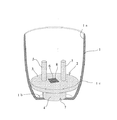
本考案の水分誘導体2は、図1及び図2に示すように、植木鉢1の中に使用するものである。
該植木鉢1は、ステンレス、プラスチック、ガラス、陶磁器などが使用でき、陶器製などの表面に水を含み濡れた状態となるような素材では内部表面1aに塗装などで非吸水性処理を施して、鉢からの吸水をしないようにしたものを使用する。
The
The
植木鉢1の中の水分誘導体2は、上記素材で底が16cm程度の径で底孔がなく、上部開口が約25cm径で高さ25cmの植木鉢1の内底1bに載置して用いる。
該水分誘導体2は、厚さ1cm程度に土を焼成して得たものであり、毛細管現象を引き起こす微細孔が全体に形成された陶器状を成すものを使用する。
該水分誘導体2は、水平な仕切盤3と、その上の棒状の放水突起5と、その下の台座4とを一体化して成る。
The
The
The
前記仕切盤3は、周囲が前記植木鉢1内の内底1bから6cm程度の低部中間高さ位置1cの水平断面形状に合致する形状に22cm径で形成する。これは、図5に示すように、前記植木鉢1の内面に嵌るように収納可能とするためである。
即ち、前記仕切盤3の周囲の形状は前記植木鉢1の形状が四角である場合には図3に示すように、その植木鉢1の大きさ及び形状を対応させて四角の形状にし、また楕円形の場合には図4に示すように、その植木鉢の大きさ及び形状を対応させて楕円の形状に形成し、前記植木鉢1の内部の低部に確実に嵌るようにする。
そして、前記仕切盤3の中央部には径が1cm程度の給水孔6を貫設する。この孔から水が前記仕切盤3下の空間に注入される。
The
That is, when the shape of the
And the
前記放水突起5は、図1に示すように、2本の径が1cm程度の棒状をなし、該仕切盤3の上面に形成され、前記植木鉢1の上部中間高さ位置に達する7cm程度の高さとし6cm程度の間隔を中央に置いて立設される。
前記放水突起5の長さ植木鉢1の深さにもよるが、3〜8cm程度が良い。
As shown in FIG. 1, the
Although depending on the length of the
前記台座4は、図1に示すように、該仕切盤3の下面に形成され、該仕切盤3を前記植木鉢1内の低部中間高さ位置1cに保持できるようにする。その高さは6cm程度が好ましい。
そして、図5に示すように、該仕切盤3下には貯水空間9を形成する。
As shown in FIG. 1, the
As shown in FIG. 5, a
以上の構成の水分誘導体2は、図5に示すように、前記貯水空間9にある水が毛細管現象で水分誘導体2内を通って吸い上げられ、前記仕切盤3及び放水突起5の表面から植木鉢1内に適度に放出されるので、前記植木鉢1内の土粒子10には適度な湿気が長期間保持可能となる。
As shown in FIG. 5, the
前記台座4の形状は、図1に示すように、その内部に中心部とその周囲の二つの貯水空間9a、9bを形成する直立円筒形にすることができる。この円筒形状の場合には、該台座4の下辺の一部を切欠して、前記両貯水空間9a、9bを繋ぐ通水切欠部7を形成し、前記給水孔6から入った水が中心部側の貯水空間9aから、その周囲の貯水空間9bへ速やかに移動できるようにする。
As shown in FIG. 1, the shape of the
次に上記水分誘導体2を内蔵した植木鉢1を説明する。
本考案の植木鉢1は、図5に示すように、底孔がなく且つ内部表面1aには非吸水性処理が施されたものを使用する。
内部表面1aを非吸水性とするのは、周囲の貯水空間9bの水が内部表面1a伝いに過剰に放出されるのを防ぎ、貯水されている水を土粒子には有効に使用して、土に使われないで放出される水の量を減らし、且つ土粒子10が過剰に濡れるのを防ぐためである。
Next, the
As shown in FIG. 5, the
The non-water absorption of the inner surface 1a prevents the water in the surrounding water storage space 9b from being excessively released along the inner surface 1a, and effectively uses the stored water for soil particles. This is to reduce the amount of water released without being used in the soil and to prevent the
この植木鉢1に中には、図2に示すように、内蔵した水分誘導体2の給水孔6の上に土落下防止網8を敷き、図5に示すように、該水分誘導体2の上に植物を植える培養土などの土粒子10を鉢内に7分目ほど入れる。
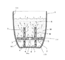
そして、使用する場合、図6に示すように、植物11を植えて、培養土などの土粒子10の上に水を撒く。この際、撒いた水が貯水空間9を満たし、その水の水位Lが前記仕切盤3の上面に達しない量に調節して水を管理する。
その際、過剰な給水を避けるため、仕切盤3の上面部位よりも僅か低い位置に水抜き孔(図省略)を設け、土粒子10の上から撒いた水の水位Lが前記仕切盤3の上面には達しない量に自動的に調節されるようにすることもできる。
In the
And when using, as shown in FIG. 6, the
At that time, in order to avoid excessive water supply, a water drain hole (not shown) is provided at a position slightly lower than the upper surface portion of the
前記植木鉢1の内部では、図6に示すように、植えた植物11の根12が前記貯水空間9から供給される水Wを求めて放水突起5を取り囲むように成長する。
そして、前記植木鉢1内の土粒子10には、粒子間の空間には水分誘導体2の上面と放水突起5とから放散される水蒸気が適度に供給される。このとき土粒子10が過剰保水の状態にならず、しかも乾き過ぎず、粒子間の空間に空気が保持された根に好ましい環境が形成される。
このため、貯水空間9に常時水が溜まっているにもかかわらず、土粒子に補給される水分量は水分誘導体2によって水蒸気などとして適度に調節されるので過剰に濡れることがなく根腐病などが起こらない。
In the
The
For this reason, although water always accumulates in the
しかし、水が仕切盤3の上面に被っていた場合には、仕切盤3の上に載っている土粒子10が直接その水を過剰に吸い上げてしまい、過剰に濡れた土で植物が根腐れ病などになりやすくなり、また植木鉢1内には過剰の水分が供給されてしまうので貯水空間9の水を短期間で放出してしまうので水遣りを頻繁に行わなければならなくなるなどの理由で好ましくはない。
そのため、前記植木鉢1の側面に、前記仕切盤3の上面より低い部位に排水孔(図省略)を備えれば、植木鉢を屋外に置いたときに、どんなに多い雨量でも、降った雨水による水位Lが仕切盤3の上面には達することがないので水位Lの調節を管理する手間がかからなくなる利点がある。
However, when water is covered on the upper surface of the
Therefore, if a drainage hole (not shown) is provided on the side surface of the
本考案の水分誘導体は、主として家庭用の植木鉢に使用するものであるが、事務所、店舗、ホテルなどの業務用の植木鉢に使用することも可能である。 The water derivative of the present invention is mainly used for a domestic flower pot, but can also be used for a business flower pot in an office, a store, a hotel or the like.
1 植木鉢
1a 植木鉢の内部表面
1b 植木鉢の内底
1c 植木鉢の低部中間高さ位置
2 水分誘導体
3 仕切盤
4 台座
4a 円筒状台座
5 放水突起
6 給水孔
7 通水切欠部
8 土落下防止網
9 貯水空間
9a 中心部の貯水空間
9b 外周部の貯水空間
10 土粒子
11 植物
12 根
S 水蒸気
W 水
L 水位
DESCRIPTION OF
S water vapor
W Water L Water level
Claims (4)
周囲が前記植木鉢内の低部中間高さ位置の水平断面形状に合致する形状に形成されると共に中央部に給水孔が貫設された水平な仕切盤と、
該仕切盤の上面に形成される、前記植木鉢の上部中間高さ位置に達する高さで立設された一本又は複数本の棒状の放水突起と、
該仕切盤の下面に形成される、該仕切盤を前記植木鉢内の低部中間高さ位置に保持して底部に貯水空間が形成される台座と、から成り、
前記植木鉢内の土粒子に適度な湿気を長期間保持可能としたことを特徴とする水分誘導体。 A pottery-like moisture derivative that is formed in a flower pot with an inner bottom without a bottom hole so that water can be stored and that has micropores that cause capillary action,
A horizontal partition having a periphery that is formed in a shape that matches the horizontal cross-sectional shape of the lower middle height position in the flowerpot and having a water supply hole penetrating in the center; and
One or a plurality of rod-like water discharge protrusions standing at a height reaching the upper middle height position of the flower pot, formed on the upper surface of the partition,
A pedestal formed on the lower surface of the partition plate, the partition plate being held at a low middle height position in the flowerpot and having a water storage space at the bottom,
A moisture derivative characterized in that moderate moisture can be maintained for a long period of time in the soil particles in the flower pot.
Priority Applications (1)
| Application Number | Priority Date | Filing Date | Title |
|---|---|---|---|
| JP2008004530U JP3144816U (en) | 2008-07-03 | 2008-07-03 | Moisture derivatives and flower pots using them |
Applications Claiming Priority (1)
| Application Number | Priority Date | Filing Date | Title |
|---|---|---|---|
| JP2008004530U JP3144816U (en) | 2008-07-03 | 2008-07-03 | Moisture derivatives and flower pots using them |
Publications (1)
| Publication Number | Publication Date |
|---|---|
| JP3144816U true JP3144816U (en) | 2008-09-11 |
Family
ID=43294647
Family Applications (1)
| Application Number | Title | Priority Date | Filing Date |
|---|---|---|---|
| JP2008004530U Expired - Fee Related JP3144816U (en) | 2008-07-03 | 2008-07-03 | Moisture derivatives and flower pots using them |
Country Status (1)
| Country | Link |
|---|---|
| JP (1) | JP3144816U (en) |
Cited By (1)
| Publication number | Priority date | Publication date | Assignee | Title |
|---|---|---|---|---|
| CN111213518A (en) * | 2020-01-16 | 2020-06-02 | 广州花生壳园艺科技有限公司 | Automatic change planting platform and commodity circulation frame and packing carton that operation flowerpot and flowerpot match |
-
2008
- 2008-07-03 JP JP2008004530U patent/JP3144816U/en not_active Expired - Fee Related
Cited By (1)
| Publication number | Priority date | Publication date | Assignee | Title |
|---|---|---|---|---|
| CN111213518A (en) * | 2020-01-16 | 2020-06-02 | 广州花生壳园艺科技有限公司 | Automatic change planting platform and commodity circulation frame and packing carton that operation flowerpot and flowerpot match |
Similar Documents
| Publication | Publication Date | Title |
|---|---|---|
| CN203608608U (en) | Water storage self-watering moisturizing flowerpot for planting scindapsus aureus | |
| JP3816444B2 (en) | Molded body for improving the cultivation state of plants | |
| CN200994310Y (en) | Flowerpot with water storage | |
| US8347552B1 (en) | Potted plant pot and saucer construction | |
| KR100933307B1 (en) | Artificial stone parts and artificial stone parts with water bag function | |
| US20050166455A1 (en) | Plant pot | |
| KR101037162B1 (en) | Flower-pot apparatus | |
| JP3144816U (en) | Moisture derivatives and flower pots using them | |
| JPS6125426A (en) | Plant watering device | |
| KR101031234B1 (en) | Flower-pot apparatus | |
| US20090119988A1 (en) | Aerial plant planter | |
| KR20160120123A (en) | Water supply device for flowerpot | |
| CN104956940A (en) | Greening facility and multi-layered building | |
| KR101638289B1 (en) | Automatic moisture control type convertible flowerpot being capable of vitalizing plants | |
| JP2003235360A (en) | Flower pot for supplying water from base having space on water surface | |
| GB2118415A (en) | Decorative flower pot | |
| JP3059615U (en) | flower pot | |
| CN206078227U (en) | Many function combination water storage flowerpot | |
| CN219877102U (en) | Moisture collecting structure | |
| KR200451153Y1 (en) | Flowerpot having storage space of water | |
| JPH0524275Y2 (en) | ||
| KR101194869B1 (en) | Flower port having function of automatically supplying water | |
| KR200491559Y1 (en) | Humidifier emitting cypress aroma | |
| CN2708637Y (en) | Automatic water supply flowerpot | |
| JP3205786U (en) | Bottom water supply type planter |
Legal Events
| Date | Code | Title | Description |
|---|---|---|---|
| R150 | Certificate of patent or registration of utility model |
Free format text: JAPANESE INTERMEDIATE CODE: R150 |
|
| FPAY | Renewal fee payment (event date is renewal date of database) |
Free format text: PAYMENT UNTIL: 20110820 Year of fee payment: 3 |
|
| FPAY | Renewal fee payment (event date is renewal date of database) |
Free format text: PAYMENT UNTIL: 20140820 Year of fee payment: 6 |
|
| LAPS | Cancellation because of no payment of annual fees |