JP3144601U - Load collapse prevention device - Google Patents

Load collapse prevention device Download PDF

Info

Publication number
JP3144601U
JP3144601U JP2008004271U JP2008004271U JP3144601U JP 3144601 U JP3144601 U JP 3144601U JP 2008004271 U JP2008004271 U JP 2008004271U JP 2008004271 U JP2008004271 U JP 2008004271U JP 3144601 U JP3144601 U JP 3144601U
Authority
JP
Japan
Prior art keywords
collapse prevention
load collapse
prevention device
leg piece
support
Prior art date
Legal status (The legal status is an assumption and is not a legal conclusion. Google has not performed a legal analysis and makes no representation as to the accuracy of the status listed.)
Expired - Fee Related
Application number
JP2008004271U
Other languages
Japanese (ja)
Inventor
廣幸 元辻
Original Assignee
廣幸 元辻
Priority date (The priority date is an assumption and is not a legal conclusion. Google has not performed a legal analysis and makes no representation as to the accuracy of the date listed.)
Filing date
Publication date
Application filed by 廣幸 元辻 filed Critical 廣幸 元辻
Priority to JP2008004271U priority Critical patent/JP3144601U/en
Application granted granted Critical
Publication of JP3144601U publication Critical patent/JP3144601U/en
Anticipated expiration legal-status Critical
Expired - Fee Related legal-status Critical Current

Links

Images

Landscapes

  • Pallets (AREA)

Abstract

【課題】取り扱いが容易で使用場所に関する制限が無く、しかも低コストな
荷崩れ防止装置を提供する。
【解決手段】パレットPに積載された物品Wに対してその外周に巻き付け可能とされる帯状のシート2と、このシート2の長手方向一端部に設けられた支柱3と、この支柱3の下端部に設けられてパレットPの外周部に係合可能とされた支持脚部材4と、シート2を物品Wまわりに巻回した状態で長手方向両端部を巻き締め保持可能にする巻き締め手段5とにより構成する。
【選択図】図1
An object of the present invention is to provide a load collapse prevention device that is easy to handle, has no restrictions on the place of use, and is low in cost.
SOLUTION: A belt-like sheet 2 that can be wound around an outer periphery of an article W loaded on a pallet P, a column 3 provided at one end in the longitudinal direction of the sheet 2, and a lower end of the column 3 A support leg member 4 that is provided on the pallet P and that can be engaged with the outer peripheral portion of the pallet P, and a winding means 5 that can hold the both ends in the longitudinal direction in a state where the sheet 2 is wound around the article W. It consists of.
[Selection] Figure 1

Description

本考案は、パレット上に積載された物品が荷崩れするのを防止できるようにした荷崩れ防止装置に関するものである。   The present invention relates to a load collapse prevention device that can prevent an article loaded on a pallet from collapsing.

パレット上に積載された物品が荷崩れするのを防止するため、物品をフィルムで包み込むようにする方法が多用されていたが、この方法ではフィルムの再利用ができないことから使い捨てとなり、高コストになるという問題や、フィルムの取り扱い(殊に物品の包装作業)が面倒であるという問題などがあった。
そこでこの問題を解消するため、物品のまわりへ包装材を巻き付けた後、この包装材をエアで膨らませて物品への巻き締め力(固定力)を高める方法及びこの方法に使用する包装材(物品包装固定具)が提案されるに至った(特許文献1参照)。この包装材は、物品の外周に巻き付ける方向を細かなピッチで区切って、同方向で縦長の気密室(エア室)が複数並ぶように形成させてあった。
In order to prevent the goods loaded on the pallet from collapsing, a method of wrapping the goods with a film has been widely used. And the problem that the handling of the film (especially the packaging operation of the article) is troublesome.
In order to solve this problem, after wrapping a packaging material around the article, the packaging material is inflated with air to increase the tightening force (fixing force) on the article, and the packaging material (article) used in this method Packaging fixtures) have been proposed (see Patent Document 1). This packaging material is formed so that a plurality of elongated airtight chambers (air chambers) are arranged in the same direction by dividing the winding direction around the outer periphery of the article with a fine pitch.

なお、包装材の下端部には、パレットへ引っ掛けるフック状の係止手段が取り付けられており、この係止手段によってパレット上での位置ズレを防止するようになっていた。
特開2004−99070号公報
Note that hook-shaped locking means for hooking onto the pallet is attached to the lower end portion of the packaging material, and position locking on the pallet is prevented by this locking means.
Japanese Patent Laid-Open No. 2004-99070

前記した従来公知の包装材(特許文献1のもの)は、エアを吹き込む前では腰の無い柔らかな状態(可撓性の豊富な状態)にあって、その意味で、布や樹脂シートと変わりのないものである。そのため、このような柔らかい包装材をパレット上の物品まわりに巻き付ける作業は非常に面倒であると共に、一人での作業では困難を極めるものとなっていた。
また、エアの吹き込みには当然に圧縮エアの供給源となる設備(コンプレッサーなど)が必要であり、使用場所が限定されてしまうという大きな問題があった。このことは、例えばパレット積みの状態のまま物品をトラック輸送する場合などにあって、トラックへの荷積み場所が限定されてしまうということである。
The above-described conventionally known packaging material (Patent Document 1) is in a soft state (a state of abundant flexibility) without air before blowing in air, and in that sense, is different from cloth or a resin sheet. There is nothing. For this reason, the operation of winding such a soft packaging material around the article on the pallet is very troublesome, and it is extremely difficult to carry out the work alone.
In addition, air blowing naturally requires equipment (such as a compressor) to be a supply source of compressed air, and there is a big problem that the place of use is limited. This means that, for example, when an article is transported by truck in a palletized state, the loading place on the truck is limited.

更に、包装材は、気密室を区画形成させるために(エアを貯められるように)表裏二重構造とする必要があり、それ自体がコスト高になっていると共に、重くて分厚くなる構造が取り扱い上の妨げになるという問題もあった。
また、この包装材は、パレット上に積載された物品への巻き始めとなる始端を一人の作業者が手でもって固定支持し、もう一人の作業者が包装材の他端側をもってパレット上の物品の回りを回ることで巻き付けし、締付具によって締付固定する必要があり、少なくとも、2人の作業者が必要となるという問題もあった。
Furthermore, the packaging material needs to have a double-sided structure (so that air can be stored) in order to form an airtight chamber, and the structure itself is expensive and heavy and thick. There was also a problem that hindered the above.
In addition, this packaging material is fixedly supported by one worker with the hand at the beginning of winding on an article loaded on the pallet, and the other worker holds the other end of the packaging material on the pallet. There is also a problem that it is necessary to wind around the article and fix it with a fastening tool, which requires at least two workers.

本考案は、上記事情に鑑みてなされたものであって、パレット上に積載された物品の荷崩れ防止に用いる荷崩れ防止装置において、1人で作業することができ、取り扱いが容易で使用場所に関する制限が無く、しかも低コストである荷崩れ防止装置を提供することを目的とする。   The present invention has been made in view of the above circumstances, and can be operated by one person in an unloading prevention apparatus used to prevent unloading of articles loaded on a pallet. It is an object of the present invention to provide a load collapse prevention device that is free of restrictions and has a low cost.

前記目的を達成するために、本考案は次の手段を講じた。
即ち、本考案に係る荷崩れ防止装置は、パレットに積載された物品に対してその外周に巻き付け可能とされる帯状のシートと、このシートの長手方向一端部に設けられた支柱と、この支柱の下端部に設けられてパレットの外周部に係合可能とされ且つこの係合状態で支柱を起立保持可能にする支持脚部材と、上記シートを物品まわりに巻回した状態で長手方向両端部を巻き締め保持可能にする巻き締め手段とを有したものである。
このような構成であると、支持脚部材をパレットに係合させることにより、パレットに対して支柱を自立状態で起立させることができる。そして、この支柱を始端としてパレット上に積載された物品のまわりへシートを巻き付けることができる。
In order to achieve the above object, the present invention has taken the following measures.
That is, the load collapse prevention device according to the present invention includes a belt-like sheet that can be wound around the outer periphery of an article loaded on a pallet, a support provided at one end in the longitudinal direction of the sheet, and the support. A support leg member which is provided at the lower end of the pallet and can be engaged with the outer peripheral part of the pallet and which can hold the column upright in this engaged state, and both ends in the longitudinal direction in a state where the sheet is wound around the article And a tightening means that makes it possible to hold the tightening.
With such a configuration, the support leg member can be engaged with the pallet, whereby the support column can be erected in an independent state with respect to the pallet. Then, the sheet can be wound around the article loaded on the pallet with the support column as a starting end.

すなわち、このようなことから、物品に対するシートの巻き付け作業を一人で行えるようになる。また、シートには1枚ものの通常のシート素材を使用可能であり、表裏二重構造のようなものは不要であるため、低コスト化も図れる。勿論、圧縮エアの供給源とするような設備も不要であるから、使用場所に関する制限もない。
支持脚部材は、パレットの側面に形成されたフォーク差込口へ挿入可能なように横突出状態で設けられており、この横突出状態で上側となる部分にフォーク差込口の内部上面と接触する上部係合面が形成され、この横突出状態で下側となる部分にフォーク差込口の内部下面と接触する下部係合面が形成されたものとすればよい。
That is, for this reason, the sheet can be wound around the article by one person. Moreover, since one sheet of normal sheet material can be used for the sheet, and a double-sided structure is not necessary, the cost can be reduced. Of course, since there is no need for a facility for supplying compressed air, there is no restriction on the place of use.
The support leg member is provided in a laterally projecting state so that it can be inserted into a fork insertion port formed on the side surface of the pallet, and the upper part of the lateral projection is in contact with the inner upper surface of the fork insertion port. An upper engagement surface is formed, and a lower engagement surface that is in contact with the inner lower surface of the fork insertion port may be formed on the lower portion in this lateral projecting state.

このようにパレットのフォーク差込口を利用して支持脚部材を係合させる構成であれば、パレット上の物品との接触干渉に影響されることがなく、パレットに対する支持脚部材の係合が可能になる。
支持脚部材は、前記上部係合面が上面に形成された上部脚片と前記下部係合面が下面に形成された下部脚片とを有していると共に、これら上部脚片と下部脚片との上下間で両片を相対的に上下離反方向へ弾性押圧する弾発部材を有したものとしてもよい。
このようにすることで、パレットのフォーク差込口に対する支持脚部材の係合が確実になる。また、パレットのフォーク差込口において、上下方向の開口寸法に多少のバラツキがあっても、弾発部材の弾性押圧力によって上部脚片と下部脚片との上下方向間隔が自動調整され、結果、パレットに対する支持脚部材の係合が可能になる。
If the support leg member is engaged using the fork insertion port of the pallet in this way, the contact of the support leg member with the pallet is not affected by contact interference with the article on the pallet. It becomes possible.
The support leg member has an upper leg piece with the upper engagement surface formed on the upper surface and a lower leg piece with the lower engagement surface formed on the lower surface, and these upper leg piece and lower leg piece. It is good also as what has the elastic member which elastically presses both pieces to the up-and-down-separation direction relatively between upper and lower.
By doing in this way, engagement of the support leg member with respect to the fork insertion port of a pallet is ensured. In addition, even if there is some variation in the vertical opening size at the fork insertion port of the pallet, the vertical distance between the upper leg piece and the lower leg piece is automatically adjusted by the elastic pressing force of the elastic member, and the result The support leg member can be engaged with the pallet.

支持脚部材は、前記上部係合面が上面に形成された上部脚片と前記下部係合面が下面に形成された下部脚片とを有しており、これら上下の脚片のうち少なくとも一方は上下移動自在に設けられ、且つ上下移動自在とされた脚片には移動後の高さ位置を固定する脚片固定手段が設けられたものとしてもよい。
このようにすることでも、パレットのフォーク差込口に対する支持脚部材の係合が確実になる。また、パレットのフォーク差込口において、上下方向の開口寸法に多少のバラツキがあっても、上部脚片と下部脚片との上下方向間隔を適宜調整後、脚片固定手段により固定すれば、パレットに対する支持脚部材の係合が可能になる。
The support leg member has an upper leg piece with the upper engagement surface formed on the upper surface and a lower leg piece with the lower engagement surface formed on the lower surface, and at least one of the upper and lower leg pieces. May be provided so as to be movable up and down, and a leg piece fixing means for fixing the height position after the movement may be provided on the leg piece that is movable up and down.
This also ensures the engagement of the support leg member with the fork insertion port of the pallet. In addition, even if there is some variation in the vertical opening size at the fork insertion port of the pallet, if the vertical distance between the upper leg piece and the lower leg piece is appropriately adjusted, and fixed by the leg piece fixing means, The support leg member can be engaged with the pallet.

シートには、前記支柱が設けられるのとは反対側となる長手方向端部に対してこの支柱と平行する状態で第2支柱が設けられたものとするのが好適である。
このようにすれば、第2支柱によってシートの帯幅(上下方向に広げた形状)が保持されるので、取り扱いが容易となり、また物品に対する巻き付け作業も容易となる。
第2支柱には、当該第2支柱を軸としてシートを巻取回収するときに第2支柱を回転させるためのハンドルが設けられたものとすればよい。
このようにすることで、シートを巻取回収するのが容易となる。
It is preferable that the sheet is provided with the second support column in a state parallel to the support column with respect to the end portion in the longitudinal direction on the opposite side to the support column.
In this way, the band width of the sheet (the shape expanded in the vertical direction) is held by the second support column, so that handling becomes easy and winding work on the article becomes easy.
The second support column may be provided with a handle for rotating the second support column when the sheet is wound and collected around the second support column.
By doing so, it becomes easy to wind up and collect the sheet.

本考案に係る荷崩れ防止装置は、1人で作業することができ、取り扱いが容易で使用場所に関する制限が無く、しかも低コストである。   The load collapse prevention device according to the present invention can be operated by one person, is easy to handle, has no restrictions on the place of use, and is low in cost.

以下、本考案の実施の形態を、図面に基づき説明する。
[第1実施形態]
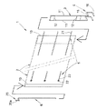
図1乃至図5は、本考案に係る荷崩れ防止装置1の第1実施形態を示している。この荷崩れ防止装置1は、帯状のシート2と、このシート2の長手方向一端部に設けられた支柱3と、この支柱3の下端部に設けられた支持脚部材4と、シート2に設けられた巻き締め手段5とを有している。またこの荷崩れ防止装置1は、シート2の他端部に設けられた第2支柱6を有している。
Hereinafter, embodiments of the present invention will be described with reference to the drawings.
[First Embodiment]
1 to 5 show a first embodiment of a load collapse prevention device 1 according to the present invention. The load collapse prevention device 1 is provided on a belt-like sheet 2, a support column 3 provided at one end portion in the longitudinal direction of the sheet 2, a support leg member 4 provided at a lower end portion of the support column 3, and the sheet 2. The tightening means 5 is provided. Further, the load collapse prevention device 1 has a second support column 6 provided at the other end of the seat 2.

シート2は、パレットPに積載された物品Wに対してその外周に巻き付け可能とされたもので、ビニールやPP等の樹脂シート、或いは布帛などにより形成することができる。耐久性や高強度性等はもとより、防水性や通気性、防かび性、耐候性、耐火性などに優れた材質を選択することも当然に、必要に応じて配慮すべき事項である。
このシート2の長手方向両端部には、支柱3や第2支柱6を保持させるため、上下に貫通する袋部10を縫製や接着などにより形成しておくと便利である。
なお、シート2の帯幅(使用時の高さ寸法:以下「高さ」と言う)や長さは、使用するパレットPや物品Wの大きさに応じて適宜決めればよい。例えば汎用的なパレットPは一辺が1000〜1100mm程度であるため、シート2の長さは4000〜4400mmなどとすればよい。また高さは1200〜1500mmなどとすればよい。
The sheet 2 can be wound around the outer periphery of the article W loaded on the pallet P, and can be formed of a resin sheet such as vinyl or PP, or a cloth. Of course, selecting materials that are superior in terms of durability, high strength, etc., as well as waterproofness, breathability, fungicidal properties, weather resistance, fire resistance, etc. is also a matter to be considered as necessary.
In order to hold the support column 3 and the second support column 6 at both longitudinal ends of the sheet 2, it is convenient to form a bag portion 10 penetrating vertically by sewing or bonding.
Note that the band width (height dimension during use: hereinafter referred to as “height”) and length of the sheet 2 may be appropriately determined according to the size of the pallet P or the article W to be used. For example, since the general pallet P has a side of about 1000 to 1100 mm, the length of the sheet 2 may be 4000 to 4400 mm. The height may be 1200 to 1500 mm.

勿論、パレットPや物品Wの大きさに合わせなければならないというものでもないので、多少の大小は許容されるものであるし、場合によっては幾つかのサイズに共通使用させるようなものとしてもよい。
支柱3は、パレットPの外周部に沿わせてシート2を起立させるときの芯(保形材)となる部分であって、シート2の高さに略相当する長さで形成されている。
本第1実施形態では、2本の丸棒素材11を平行させて、それらの長手方向適所を連結板12で連結させることによって製作してある。丸棒素材11は金属製としたり樹脂製としたりすればよい。場合によっては丸棒素材11を木製とすることも可能である。
Of course, since it does not have to match the size of the pallet P or the article W, some size is acceptable, and in some cases, it may be used in common for several sizes. .
The support column 3 is a portion that becomes a core (shape-retaining material) when the sheet 2 is erected along the outer peripheral portion of the pallet P, and is formed with a length substantially corresponding to the height of the sheet 2.
In the first embodiment, the two round bar materials 11 are made parallel to each other and connected at appropriate positions in the longitudinal direction by the connecting plate 12. The round bar material 11 may be made of metal or resin. In some cases, the round bar material 11 can be made of wood.

図4に示すように、支持脚部材4は、パレットPの外周部に係合可能とされたもので、支柱3の下端部から、パレットPの側面に形成されたフォーク差込口hへ向けて挿入可能なように横突出状態で設けられている。
支持脚部材4において、この横突出状態で上側となる部分は、フォーク差込口hの内部上面と接触する上部係合面15として形成されている。また、この横突出状態で下側となる部分は、フォーク差込口hの内部下面と接触する下部係合面16として形成されている。
As shown in FIG. 4, the support leg member 4 can be engaged with the outer peripheral portion of the pallet P, and is directed from the lower end portion of the support column 3 to the fork insertion port h formed on the side surface of the pallet P. So that it can be inserted.
In the support leg member 4, the upper portion in the laterally protruding state is formed as an upper engagement surface 15 that contacts the inner upper surface of the fork insertion port h. Further, the lower part in the lateral projecting state is formed as a lower engagement surface 16 that comes into contact with the inner lower surface of the fork insertion port h.

これら上部係合面15と下部係合面16とは、支持脚部材4をパレットPのフォーク差込口hに差し込んだとき、フォーク差込口hの内部上面と内部下面とに対して同時に接触し、且つ上下相反する方向へ押圧する状態となっている(上部係合面15は内部上面を上向きに押圧し下部係合面16は内部下面を下向きに押圧する)。
そのため、フォーク差込口h内で支持脚部材4はガタツキなく係合した状態が得られ、この支持脚部材4の上部で支柱3が起立した状態が保持されるようになっている。なお、意欲をもって支持脚部材4をフォーク差込口hから引き出すようにすれば、比較的容易に支持脚部材4を引き出せる程度の係合力となっている。
The upper engagement surface 15 and the lower engagement surface 16 contact the inner upper surface and the inner lower surface of the fork insertion port h at the same time when the support leg member 4 is inserted into the fork insertion port h of the pallet P. The upper engagement surface 15 presses the inner upper surface upward and the lower engagement surface 16 presses the inner lower surface downward.
For this reason, the support leg member 4 is engaged in the fork insertion port h without any backlash, and the support column 3 is held upright above the support leg member 4. If the support leg member 4 is pulled out from the fork insertion port h with motivation, the engagement force is such that the support leg member 4 can be pulled out relatively easily.

本第1実施形態において支持脚部材4は、支柱3を形成している丸棒素材11の下端部をコ字状に折曲させることで、支柱3と支持脚部材4とが一体形成されるようにしてある。また、パレットPのフォーク差込口hに対して挿入し易さを考慮して、横突出する先方ほど当該支持脚部材4の高さ寸法が若干小さくなるように、上部係合面15には下り傾斜を、また下部係合面16には上り傾斜を、それぞれ付してある。
第2支柱6は、シート2において、支柱3が設けられるのとは反対側となる長手方向端部に対してこの支柱3と平行する状態で設けられている。この第2支柱6によってもシート2の高さが保形されるようになるので、シート2の取り扱いが容易となり、またシート2を物品Wに対して巻き付けたり、その後、物品Wからシート2を取り除いたりする作業も容易に行えるようになる。
In the first embodiment, the support leg member 4 is formed integrally with the support column 3 and the support leg member 4 by bending the lower end portion of the round bar material 11 forming the support column 3 into a U shape. It is like that. In consideration of ease of insertion into the fork insertion port h of the pallet P, the upper engagement surface 15 has a lower height so that the height of the support leg member 4 is slightly smaller toward the tip protruding laterally. A downward inclination and an upward inclination are given to the lower engagement surface 16.
The second support column 6 is provided in a state parallel to the support column 3 with respect to the longitudinal end portion on the opposite side to the support column 3 in the seat 2. Since the height of the sheet 2 is also maintained by the second support column 6, the handling of the sheet 2 is facilitated, the sheet 2 is wound around the article W, and then the sheet 2 is removed from the article W. The removal work can be easily performed.

なお、この第2支柱6には上端部にハンドル20が設けられている。このハンドル20は上方へ突出する握り部20aを有したもので、この握り部20aは、第2支柱6に対してクランク状に折れ曲がった状態で配置されている(第2支柱6の軸心からズレた位置で上方突出している)。
そのため、第2支柱6の軸心を支点にして握り部20aを旋回させるようにすると、第2支柱6を軸としてそのまわりにシート2を巻き取らせることができる。すなわち、物品Wへ巻き付けたシート2をその後に取り除く際、ハンドル20を旋回操作しつつシート2を物品Wから剥がしてゆくようにすれば、シート2を第2支柱6まわりに巻取回収することができる。
Note that a handle 20 is provided at the upper end of the second support column 6. The handle 20 has a grip portion 20a that protrudes upward. The grip portion 20a is disposed in a state of being bent in a crank shape with respect to the second support column 6 (from the axis of the second support column 6). It protrudes upwards at a shifted position).
Therefore, when the grip 20a is turned around the axis of the second support column 6 as a fulcrum, the seat 2 can be wound around the second support column 6 as an axis. That is, when the sheet 2 wound around the article W is subsequently removed, if the sheet 2 is peeled off from the article W while turning the handle 20, the sheet 2 is wound around the second column 6 and collected. Can do.

そのため、物品Wから取り外したシート2をコンパクトにまとめることができ、その後の取り扱いが容易であると共に、シート2の再利用(物品Wへの巻き付け)も簡単に行えるようになる。勿論、これらの作業を一人で行える利点もある。
巻き締め手段5は、シート2を物品Wまわりに巻回したときに(図2参照)、このシート2の長手方向両端部を巻き締め保持させるためのものである。具体的な構造は特に限定されるものではないが、繰り返しの使用が可能であることが必要である。
本第1実施形態では、シート2の長手方向一端側に可撓性の紐状部材21を設け、シート2の長手方向他端側には、紐状部材21を通すリング部材22を設けて、これら紐状部材21とリング部材22とで連結離反可能にしてある。なお、図例ではこれら紐状部材21とリング部材22との組み合わせを、上下3箇所に設けてあるが、設置数や配置などは何ら限定されるものではない。
Therefore, the sheet 2 removed from the article W can be collected in a compact manner, the subsequent handling is easy, and the sheet 2 can be easily reused (wrapped around the article W). Of course, there is an advantage that these operations can be performed alone.
When the sheet 2 is wound around the article W (see FIG. 2), the winding means 5 is for holding the both ends of the sheet 2 in the longitudinal direction. The specific structure is not particularly limited, but it is necessary that the structure can be used repeatedly.
In the first embodiment, a flexible string-like member 21 is provided on one end side in the longitudinal direction of the sheet 2, and a ring member 22 through which the string-like member 21 is passed is provided on the other end side in the longitudinal direction of the sheet 2. The string-like member 21 and the ring member 22 can be connected and separated. In the example shown in the drawing, the combination of the string-like member 21 and the ring member 22 is provided at three positions in the upper and lower directions, but the number of installations and the arrangement are not limited at all.

紐状部材21はナイロン等の樹脂製ベルト等によって形成することができる。その他、布製や皮製、金属製(チェーン等)などとしてもよい。またリング部材22も、好ましくは樹脂ベルト23等を介してシート2に取り付けておくのがよい。
紐状部材21とリング部材22との連結は、図5に示すように、紐状部材21を2個のリング部材22へ挿し通して折り返した後、その折り返し端部を2個のリング部材のうちの一方を通して引き出すことにより緊締状態で係止保持させる構造などを採用可能である。
The string-like member 21 can be formed by a resin belt such as nylon. In addition, it may be made of cloth, leather, metal (such as a chain), or the like. The ring member 22 is also preferably attached to the seat 2 via a resin belt 23 or the like.
As shown in FIG. 5, the string-like member 21 and the ring member 22 are connected by inserting the string-like member 21 into the two ring members 22 and turning them back, and then turning the folded end portions of the two ring members. It is possible to adopt a structure in which it is locked and held in a tightened state by being pulled out through one of them.

なお、図示は省略するが、衣類(ズボン等)で多用されるようなベルトとベルト通しによる連結構造等を採用することも可能である。
以上、詳説したところから明かなように、上記構成を具備した本考案の荷崩れ防止装置1では、図3に示すように、シート2の長手方向一端部(広口の袋部10)へ支柱3を差し込むと共に、シート2の長手方向他端部(狭口の袋部10)へ第2支柱6を差し込んでおく。これら支柱3や第2支柱6は、各袋部10に差し込んだ状態で固定しておいてもよい。
In addition, although illustration is abbreviate | omitted, it is also possible to employ | adopt the connection structure etc. by the belt and belt loop which are often used with clothing (trousers etc.).
As is apparent from the above description, in the load collapse prevention device 1 of the present invention having the above-described configuration, as shown in FIG. 3, the column 3 is attached to one longitudinal end portion (the wide-mouthed bag portion 10) of the seat 2. And the second support column 6 is inserted into the other end in the longitudinal direction of the sheet 2 (narrow bag portion 10). You may fix these support | pillars 3 and the 2nd support | pillar 6 in the state inserted in each bag part 10. FIG.

そして、図1に示すように、物品Wを積載状態にあるパレットPに対し、そのフォーク差込口hのうちいずれかへ支持脚部材4を差し込み、係合させる。これにより、パレットPの外周部で支柱3を起立状態に保持させる。
次に、図2に示すように、支柱3を始点としてパレットP上の物品Wまわりへシート2を巻き付けてゆく。このとき、第2支柱6を把持するようにするとシート2を広げたまま巻き付け作業を進行できるため、作業が容易である。
支柱3の起立位置までシート2を巻き付けた状態で、巻き締め手段5を連結状態にする(図5参照)。このように、物品Wに対するシート2の巻き付け作業は一人で行える。
Then, as shown in FIG. 1, the support leg member 4 is inserted into and engaged with one of the fork insertion ports h with respect to the pallet P in which the articles W are loaded. Thereby, the support | pillar 3 is hold | maintained in the standing state in the outer peripheral part of the pallet P. FIG.
Next, as shown in FIG. 2, the sheet 2 is wound around the article W on the pallet P with the column 3 as a starting point. At this time, if the second support column 6 is gripped, the winding operation can be performed while the sheet 2 is expanded, so that the operation is easy.
In a state where the sheet 2 is wound up to the standing position of the support column 3, the winding fastening means 5 is brought into a connected state (see FIG. 5). Thus, the winding operation of the sheet 2 around the article W can be performed by one person.

以上のように、物品Wのまわりはシート2によって巻回され、固定されるので、搬送振動などで物品Wが荷崩れを起こすおそれはなくなる。
[第2実施形態]
図6及び図7は、本考案に係る荷崩れ防止装置1の第2実施形態を示している。本第2実施形態の荷崩れ防止装置1が第1実施形態と最も異なるところは、支柱3の下端部に設けられた支持脚部材4が上部脚片30と下部脚片31とを有し、且つこれら上部脚片30と下部脚片31との上下間に弾発部材32が設けられている点にある。
As described above, since the area around the article W is wound and fixed by the sheet 2, there is no possibility that the article W will collapse due to conveyance vibration or the like.
[Second Embodiment]
6 and 7 show a second embodiment of the load collapse prevention device 1 according to the present invention. The place where the load collapse prevention device 1 of the second embodiment is most different from the first embodiment is that the support leg member 4 provided at the lower end of the support column 3 has an upper leg piece 30 and a lower leg piece 31. In addition, a resilient member 32 is provided between the upper and lower leg pieces 30 and 31.

なお、支柱3は1本の角棒素材33により形成されたものとしている点も第1実施形態と異なるところである。
支持脚部材4において、上部脚片30及び下部脚片31は板材により形成されている。そのため、上部脚片30の上面に、フォーク差込口hの内部上面と接触する上部係合面15が形成され、下部脚片31の下面に、フォーク差込口hの内部下面と接触する下部係合面16が形成されることになる。
上部脚片30には支柱3をガタツキ無く挿通可能にする柱孔36が形成されており、この柱孔36内に支柱3が串刺し状に挿通されている。支柱3が角棒素材33により形成されているため、柱孔36は角穴になっている。すなわち、上部脚片30は支柱3とは固定されておらず、支柱3に沿って上下に移動自在となっている。
In addition, the point which the support | pillar 3 shall be formed with the one square bar raw material 33 is a place different from 1st Embodiment.
In the support leg member 4, the upper leg piece 30 and the lower leg piece 31 are formed of a plate material. Therefore, an upper engagement surface 15 that contacts the inner upper surface of the fork insertion port h is formed on the upper surface of the upper leg piece 30, and a lower portion that contacts the inner lower surface of the fork insertion port h on the lower surface of the lower leg piece 31. An engagement surface 16 is formed.
A column hole 36 is formed in the upper leg piece 30 so that the column 3 can be inserted without rattling. The column 3 is inserted into the column hole 36 like a skewer. Since the column 3 is formed of a square bar material 33, the column hole 36 is a square hole. That is, the upper leg piece 30 is not fixed to the support column 3 and is movable up and down along the support column 3.

また、上部脚片30にはこの柱孔36に近接する位置に背部鍔37が設けられている。この背部鍔37は、上部脚片30の上方又は下方へ折曲状に設けられたもので(図例では上方とした)、上部脚片30の剛性を高める作用もある。この背部鍔37には脚片固定手段38が設けられている。
この脚片固定手段38は、柱孔36内へ支柱3が挿通されたときに、この支柱3と合致する配置で設けられた雌ねじ孔39と、この雌ねじ孔39に螺合されたセットボルト40とを有している。
The upper leg piece 30 is provided with a back collar 37 at a position close to the column hole 36. The back barb 37 is provided in a bent shape above or below the upper leg piece 30 (in the example shown above), and also has an effect of increasing the rigidity of the upper leg piece 30. The back collar 37 is provided with leg piece fixing means 38.
The leg piece fixing means 38 includes a female screw hole 39 provided in an arrangement that matches the column 3 when the column 3 is inserted into the column hole 36, and a set bolt 40 screwed into the female screw hole 39. And have.

セットボルト40には蝶ボルトが用いられており、手で緩めたり締め込んだりの操作が可能となっている。すなわち、このセットボルト40を締め付けるとそのボルト先端が支柱3に当接してブレーキ力を発生し、支柱3に対する上部脚片30の位置決めが可能になる。またセットボルト40を緩めた状態では、支柱3に沿って上部脚片30の上下移動が自在となる。
背部鍔37には、その左右両側に側部鍔41が設けられている。これら左右の側部鍔41は、支持脚部材4をパレットPのフォーク差込口hへ差し込んだとき、支柱3と一緒にパレットPの側面に当接するようになっている(図7参照)。そのため、パレットPの側面に対して、支柱3を中心にしてその左右両側に左右の側部鍔41が当接した3点支持状態が得られることになる。従って、パレットPに対する支持脚部材4の係合状態の安定、ひいては支柱3の起立状態の安定が得られるという利点に繋がる。
A butterfly bolt is used for the set bolt 40 and can be loosened or tightened by hand. That is, when the set bolt 40 is tightened, the tip of the bolt abuts on the support 3 to generate a braking force, and the upper leg piece 30 can be positioned with respect to the support 3. Further, when the set bolt 40 is loosened, the upper leg piece 30 can be moved up and down along the column 3.
The back collar 37 is provided with side collars 41 on the left and right sides thereof. These left and right side rods 41 come into contact with the side surface of the pallet P together with the support column 3 when the support leg member 4 is inserted into the fork insertion port h of the pallet P (see FIG. 7). Therefore, a three-point support state in which the left and right side rods 41 are in contact with the left and right sides of the column 3 with respect to the side surface of the pallet P is obtained. Therefore, it leads to the advantage that the stability of the engagement state of the support leg member 4 with respect to the pallet P and the stability of the standing state of the column 3 can be obtained.

下部脚片31は、支柱3に対して溶接などにより固定された状態にある。
弾発部材32は、上部脚片30と下部脚片31を相対的に上下離反方向へ弾性押圧するためのものである。本第2実施形態では、上下のバネ板部32a,32bが側面視「く」字状に折曲形成された板バネを採用して弾発部材32を形成してある。この弾発部材32には上下のバネ板部32a,32bから後方へ突き出すようにして係合突起42が突設されている。
一方、支柱3には、上のバネ板部32aに設けられた係合突起42と係合可能な上部係合孔43が設けられていると共に、下のバネ板部32bに設けられた係合突起42と係合可能な下部係合孔44が設けられている。
The lower leg piece 31 is fixed to the support column 3 by welding or the like.
The resilient member 32 is for elastically pressing the upper leg piece 30 and the lower leg piece 31 relatively in the vertical direction. In the second embodiment, the elastic member 32 is formed by adopting a plate spring in which the upper and lower spring plate portions 32a and 32b are bent in a "<" shape when viewed from the side. Engaging protrusions 42 project from the elastic member 32 so as to protrude rearward from the upper and lower spring plate portions 32a and 32b.
On the other hand, the support 3 is provided with an upper engagement hole 43 that can be engaged with an engagement protrusion 42 provided in the upper spring plate portion 32a, and an engagement provided in the lower spring plate portion 32b. A lower engagement hole 44 that can be engaged with the protrusion 42 is provided.

このうち、上部係合孔43は上下に長い長孔とされ、下部係合孔44は上下に短い丸孔又は角穴とされている。
このような構成を具備して成る第2実施形態の荷崩れ防止装置1では、パレットPのフォーク差込口hにおいて、その上下方向の開口寸法に種々のサイズが存在するとき(例えば80mm〜100mmのものが一般に多く流通している)、或いは多少の寸法バラツキがあったときにも対応できる。
すなわち、予め、支持脚部材4に設けられたセットボルト40を緩めから上部脚片30と下部脚片31との上下間隔を弾発部材32の弾発力に抗しつつ、狭めるようにし、必要に応じてこの状態でセットボルト40を一旦、仮締めする。そして支持脚部材4をフォーク差込口hへ差し込んでからセットボルト40をもう一度、緩めるようにする。
Among these, the upper engagement hole 43 is a long hole that is long in the vertical direction, and the lower engagement hole 44 is a short round hole or a square hole in the vertical direction.
In the load collapse prevention device 1 according to the second embodiment having such a configuration, when there are various sizes of opening dimensions in the vertical direction at the fork insertion port h of the pallet P (for example, 80 mm to 100 mm). In general, many products are distributed), or when there is some dimensional variation.
That is, the set bolt 40 provided on the support leg member 4 is loosened in advance, and the vertical distance between the upper leg piece 30 and the lower leg piece 31 is narrowed against the elastic force of the elastic member 32. Accordingly, the set bolt 40 is temporarily tightened in this state. Then, after the support leg member 4 is inserted into the fork insertion port h, the set bolt 40 is once again loosened.

このようにすることで、上部脚片30と下部脚片31との上下間隔が弾発部材32の作用で広げられ、フォーク差込口hにおける上下方向の開口寸法に応じて自動的に調整されることになる。即ち、パレットPのフォーク差込口hに対する支持脚部材4の係合が確実に行えるようになる。その後、セットボルト40を締め込むようにすればよい。
[第3実施形態]
図8及び図9は、本考案に係る荷崩れ防止装置1の第3実施形態を示している。本第3実施形態の荷崩れ防止装置1は、上記した第2実施形態(図6及び図7参照)とほぼ同じで、支柱3の下端部に設けられた支持脚部材4が上部脚片30と下部脚片31とを有し、且つこれら上部脚片30と下部脚片31との上下間に弾発部材32が設けられている。
By doing so, the vertical distance between the upper leg piece 30 and the lower leg piece 31 is widened by the action of the elastic member 32, and is automatically adjusted according to the vertical opening size at the fork insertion port h. Will be. That is, the support leg member 4 can be reliably engaged with the fork insertion port h of the pallet P. Thereafter, the set bolt 40 may be tightened.
[Third Embodiment]
8 and 9 show a third embodiment of the load collapse prevention device 1 according to the present invention. The load collapse prevention device 1 of the third embodiment is substantially the same as the second embodiment described above (see FIGS. 6 and 7), and the support leg member 4 provided at the lower end portion of the support column 3 includes the upper leg piece 30. And a lower leg piece 31, and a resilient member 32 is provided between the upper leg piece 30 and the lower leg piece 31.

第2実施形態との違いは、弾発部材32としてコイルスプリングを採用している点にある。
弾発部材32がコイルスプリングであることから、上部脚片30の下面及び下部脚片31の上面には、コイルスプリングのリング内に嵌合可能な位置決めボス45,46が設けられている。
この他の構成、及び作用効果については第2実施形態と略同様であるため、ここでの詳説は省略する。
[第4実施形態]
図10及び図11は、本考案に係る荷崩れ防止装置1の第4実施形態を示している。本第4実施形態の荷崩れ防止装置1についても、上記した第2実施形態(図6及び図7参照)とほぼ同じで、支柱3の下端部に設けられた支持脚部材4が上部脚片30と下部脚片31とを有し、且つこれら上部脚片30と下部脚片31との上下間に弾発部材32が設けられている。
The difference from the second embodiment is that a coil spring is adopted as the elastic member 32.
Since the elastic member 32 is a coil spring, positioning bosses 45 and 46 that can be fitted into the ring of the coil spring are provided on the lower surface of the upper leg piece 30 and the upper surface of the lower leg piece 31.
Since other configurations and operational effects are substantially the same as those of the second embodiment, detailed description thereof is omitted here.
[Fourth Embodiment]
10 and 11 show a fourth embodiment of the load collapse prevention device 1 according to the present invention. The load collapse prevention device 1 of the fourth embodiment is also substantially the same as the second embodiment (see FIGS. 6 and 7), and the support leg member 4 provided at the lower end of the column 3 is an upper leg piece. 30 and a lower leg piece 31, and a resilient member 32 is provided between the upper leg piece 30 and the lower leg piece 31.

第2実施形態との違いは、弾発部材32としてコイルスプリングを採用し、更にこのコイルスプリングを上部脚片30と下部脚片31との上下間において支柱3に挿通させている点にある。
このため、上記第3実施形態(図8及び図9参照)とは異なり、上部脚片30の下面や下部脚片31の上面に位置決めボス45,46を設ける必要がなく、構造の簡潔化、低コスト化、軽量化などが図れる利点がある。
なお、本第4実施形態では、上部脚片30の背部鍔37に対し、後方へ張り出すような状態で後部鍔47が設けられている。この後部鍔47は、上部脚片30を下方へ押し下げる操作が容易に行えるようにするためのもので、作業者の足を掛けたり、又は手を掛けたりできるようになっている。
The difference from the second embodiment is that a coil spring is adopted as the elastic member 32 and this coil spring is inserted into the support column 3 between the upper leg piece 30 and the lower leg piece 31.
Therefore, unlike the third embodiment (see FIGS. 8 and 9), there is no need to provide positioning bosses 45 and 46 on the lower surface of the upper leg piece 30 and the upper surface of the lower leg piece 31, and the structure is simplified. There are advantages such as cost reduction and weight reduction.
In the fourth embodiment, the rear collar 47 is provided so as to protrude rearward from the back collar 37 of the upper leg piece 30. The rear rod 47 is for facilitating an operation of pushing down the upper leg piece 30 downward, and can be put on an operator's foot or a hand.

この他の構成、及び作用効果については第2、第3実施形態と略同様であるため、ここでの詳説は省略する。
[第5実施形態]
図12及び図13は、本考案に係る荷崩れ防止装置1の第5実施形態を示している。本第5実施形態の荷崩れ防止装置1は、上記した第2実施形態(図6及び図7参照)、第3実施形態(図8及び図9参照)、第4実施形態(図10及び図11参照)から弾発部材32を省略したのと略同じ構成である。
Since other configurations and operational effects are substantially the same as those of the second and third embodiments, detailed description thereof is omitted here.
[Fifth Embodiment]
12 and 13 show a fifth embodiment of the load collapse prevention device 1 according to the present invention. The load collapse prevention device 1 of the fifth embodiment includes the second embodiment (see FIGS. 6 and 7), the third embodiment (see FIGS. 8 and 9), and the fourth embodiment (see FIGS. 10 and 7). 11), and the elastic member 32 is substantially the same configuration.

すなわち、支柱3の下端部に設けられた支持脚部材4が上部脚片30と下部脚片31とを有したものである。また上部脚片30には脚片固定手段38が設けられている。
この他の構成、及び作用効果については、弾発部材32によるものを除いて第2〜第4実施形態と略同様であるため、ここでの詳説は省略する。
[第6実施形態]
図14は、本考案に係る荷崩れ防止装置1の第6実施形態を示している。本第6実施形態の荷崩れ防止装置1は、上記した第5実施形態(図12及び図13参照)とほぼ同じで、支持脚部材4が上部脚片30と下部脚片31とを有し、また上部脚片30に脚片固定手段38が設けられたものである。
That is, the support leg member 4 provided at the lower end portion of the column 3 has the upper leg piece 30 and the lower leg piece 31. The upper leg piece 30 is provided with leg piece fixing means 38.
Since other configurations and operational effects are substantially the same as those of the second to fourth embodiments except for those by the elastic member 32, detailed description thereof is omitted here.
[Sixth Embodiment]
FIG. 14 shows a sixth embodiment of the load collapse prevention device 1 according to the present invention. The load collapse prevention device 1 of the sixth embodiment is substantially the same as the fifth embodiment (see FIGS. 12 and 13), and the support leg member 4 has an upper leg piece 30 and a lower leg piece 31. The upper leg piece 30 is provided with leg piece fixing means 38.

第5実施形態との違いは、支柱3を形成する角棒素材33をL型に折曲することにより、この折曲部分で支持脚部材4の下部脚片31を形成させている点にある。すなわち、支柱3と下部脚片31とが一体形成されているため、部品点数が減少しており、構造の簡潔化、低コスト化、軽量化などが図れる利点がある。
この他の構成、及び作用効果については第5実施形態と略同様であるため、ここでの詳説は省略する。
[第7実施形態]
図15は、本考案に係る荷崩れ防止装置1の第7実施形態を示している。本第7実施形態の荷崩れ防止装置1が具備する支柱3は、上記した第1実施形態(図1乃至図5参照)で説明した支柱3と同様に、2本の丸棒素材11によって形成されたものである。
The difference from the fifth embodiment is that the lower leg piece 31 of the support leg member 4 is formed at the bent portion by bending the square bar material 33 forming the support column 3 into an L shape. . That is, since the column 3 and the lower leg piece 31 are integrally formed, the number of parts is reduced, and there is an advantage that the structure can be simplified, the cost can be reduced, and the weight can be reduced.
Since other configurations and operational effects are substantially the same as those of the fifth embodiment, detailed description thereof is omitted here.
[Seventh Embodiment]
FIG. 15 shows a seventh embodiment of the load collapse prevention device 1 according to the present invention. The support column 3 included in the load collapse prevention device 1 of the seventh embodiment is formed by two round bar materials 11 in the same manner as the support column 3 described in the first embodiment (see FIGS. 1 to 5). It has been done.

ただ第1実施形態と異なり、丸棒素材11の下端部をL型に折曲することで支持脚部材4の下部脚片31だけを形成させている。
そして、支持脚部材4の上部脚片30については別部材により形成させている。この上部脚片30には支柱3へ突き当てる方の端部に雌ねじ部50が形成されており、支柱3にはこの雌ねじ部50へ螺合するストッパボルト51を貫通させるためのボルト通孔52が形成されている。このボルト通孔52は、上下方向に長い長孔として形成されている。
このようなことから明かなように、本第7実施形態においては、支持脚部材4の上部脚片30の方が上下移動自在となっており、雌ねじ部50、ストッパボルト51、ボルト通孔52によって脚片固定手段38が構成されているものである。
However, unlike the first embodiment, only the lower leg piece 31 of the support leg member 4 is formed by bending the lower end portion of the round bar material 11 into an L shape.
The upper leg piece 30 of the support leg member 4 is formed by a separate member. The upper leg piece 30 is formed with a female threaded portion 50 at the end that abuts against the column 3, and the column 3 has a bolt through hole 52 through which a stopper bolt 51 screwed into the female threaded portion 50 is passed. Is formed. The bolt through hole 52 is formed as a long hole that is long in the vertical direction.
As is apparent from the above, in the seventh embodiment, the upper leg piece 30 of the support leg member 4 is movable up and down, and the internal thread portion 50, the stopper bolt 51, and the bolt through hole 52. Thus, the leg piece fixing means 38 is constituted.

この他の構成、及び作用効果については、支持脚部材4の上部脚片30を上下移動させる点を除いては第1実施形態と略同様であり、またこの上部脚片30を上下移動させる点に関しては第6実施形態と略同様であるため、ここでの詳説は省略する。
[その他]
図16は、支持脚部材4の別実施形態を示している。この図16に示した支持脚部材4は、例えば樹脂やゴムなどで一体的に形成された中空又は中実の塊状に形成されている。従って、その塊状の上面が上部係合面15として形成され、下面が下部係合面16として形成されたものであり、他実施形態で説明した「上部脚片30」や「下部脚片31」に該当するような独立部材は存在しない。
Other configurations and operational effects are substantially the same as those of the first embodiment except that the upper leg piece 30 of the support leg member 4 is moved up and down, and the upper leg piece 30 is moved up and down. Since this is substantially the same as that of the sixth embodiment, detailed description thereof is omitted here.
[Others]
FIG. 16 shows another embodiment of the support leg member 4. The support leg member 4 shown in FIG. 16 is formed in a hollow or solid lump formed integrally with, for example, resin or rubber. Accordingly, the upper surface of the lump is formed as the upper engagement surface 15 and the lower surface is formed as the lower engagement surface 16, and the “upper leg piece 30” and “lower leg piece 31” described in the other embodiments. There is no independent member that falls under.

図17は、支持脚部材4の更に別の実施形態を示している。この図17に示した支持脚部材4は、側面視形状が横倒した「V」字状を呈するように、上部バネ板部48aと下部バネ板部48bとを有した板バネで形成したものである。
当然に、上部バネ板部48aの上面が上部係合面15を形成し、下部バネ板部48bの下面が下部係合面16を形成するものとなる。このような支持脚部材4では、上部係合面15や下部係合面16自体が上下方向の弾発力を生ずるようになるので、これらが上記した第2実施形態(図6及び図7参照)、第3実施形態(図8及び図9参照)、第4実施形態(図10及び図11参照)の弾発部材32の代用としての作用することになる。
FIG. 17 shows still another embodiment of the support leg member 4. The support leg member 4 shown in FIG. 17 is formed of a leaf spring having an upper spring plate portion 48a and a lower spring plate portion 48b so that the shape of the supporting leg member 4 is a "V" shape whose side view is lying sideways. is there.
Naturally, the upper surface of the upper spring plate portion 48 a forms the upper engagement surface 15, and the lower surface of the lower spring plate portion 48 b forms the lower engagement surface 16. In such a support leg member 4, the upper engagement surface 15 and the lower engagement surface 16 themselves generate an elastic force in the vertical direction, which is the second embodiment described above (see FIGS. 6 and 7). ), Acting as a substitute for the resilient member 32 of the third embodiment (see FIGS. 8 and 9) and the fourth embodiment (see FIGS. 10 and 11).

すなわち、弾発部材32の省略が可能であり、部品点数を減少させられるので、構造の簡潔化、低コスト化、軽量化などが図れる利点がある。
図18は、第2支柱6に関する別実施形態を示している。この図18に示した第2支柱6は、ハンドル20を回転不能に支持するハンドル支え54に対し、その両側に2枚の細幅板材55を平行に設けたもので、細幅板材55の相互間には隙間56が形成されている。
このような第2支柱6であれば、シート2に対してわざわざ取付用の袋部10(図1や図3等参照)を設けておかなくても、2枚の細幅板材55でシート2を挟持させるようにすることで(隙間56へシート2を差し込むことで)、シート2への取り付けが可能になる。そのため、シート2として低コスト化が可能になるという利点がある。
That is, the elastic member 32 can be omitted, and the number of parts can be reduced, so that there is an advantage that the structure can be simplified, the cost can be reduced, and the weight can be reduced.
FIG. 18 shows another embodiment relating to the second support column 6. The second support column 6 shown in FIG. 18 has two narrow plate members 55 provided in parallel to both sides of a handle support 54 that supports the handle 20 in a non-rotatable manner. A gap 56 is formed between them.
In the case of such a second support column 6, the sheet 2 can be formed with two narrow plate members 55 even if the bag portion 10 (see FIG. 1, FIG. 3, etc.) is not provided for the sheet 2. Can be attached to the sheet 2 (by inserting the sheet 2 into the gap 56). Therefore, there is an advantage that the cost of the sheet 2 can be reduced.

また図19は、第2支柱6における更に別の実施形態を示している。この図19に示した第2支柱6は、1枚の細幅板材55によって形成されたもので、その上端部にはハンドル20の連結に用いる係合突起58が設けられている。この係合突起58は、平面視形状が円形以外(図例では正方形)を呈するように形成されている。
これに対してハンドル20には、下端部に上記係合突起58とガタツキ無く嵌合可能となる連結孔59が形成されている。この連結孔59の開口形状は、係合突起58と同様に円形以外(図例では正方形)を呈するように形成されている。
FIG. 19 shows still another embodiment of the second support column 6. The second column 6 shown in FIG. 19 is formed by a single narrow plate material 55, and an engagement protrusion 58 used for connecting the handle 20 is provided at the upper end portion thereof. The engaging protrusions 58 are formed so that the shape in plan view exhibits a shape other than a circle (a square in the illustrated example).
On the other hand, the handle 20 is formed with a connecting hole 59 at the lower end portion that can be fitted to the engaging protrusion 58 without rattling. The opening shape of the connection hole 59 is formed to have a shape other than a circle (square in the illustrated example) like the engagement protrusion 58.

このようなことから、ハンドル20と細幅板材55とを着脱自在とできるものであり、互いの連結時には第2支柱6を全体として(即ち、ハンドル20と細幅板材55)一体回転可能となっている。
本考案は、上記各実施形態に限定されるものではなく、実施の形態に応じて適宜変更可能である。
例えば、第2支柱6において、ハンドル20はクランク形状の一部又は全体を伸長させたり折り曲げたりできるような構造にすることも可能である。また、ハンドル20は、ダイヤル形状(丸ハンドル)等をしたものに変更することも可能である。
For this reason, the handle 20 and the narrow plate member 55 can be freely attached and detached, and the second support 6 can be rotated as a whole (that is, the handle 20 and the narrow plate member 55) when connected to each other. ing.
The present invention is not limited to the above-described embodiments, and can be appropriately changed according to the embodiments.
For example, in the second support column 6, the handle 20 can be structured such that a part or the whole of the crank shape can be extended or folded. The handle 20 can be changed to a dial shape (round handle) or the like.

シート2には網素材を採用することも可能である。
その他、支柱3や第2支柱6など、材質や細部形状などは何ら限定されるものではない。
It is also possible to employ a net material for the sheet 2.
In addition, the material, the detailed shape, and the like of the support column 3 and the second support column 6 are not limited at all.

本考案に係る荷崩れ防止装置の第1実施形態を示した斜視図である。It is the perspective view which showed 1st Embodiment of the load collapse prevention apparatus which concerns on this invention. 第1実施形態の荷崩れ防止装置において物品へ巻き付ける様子を示した斜視図である。It is the perspective view which showed a mode that it wound around articles | goods in the load collapse prevention apparatus of 1st Embodiment. 第1実施形態の荷崩れ防止装置を示した分解斜視図である。It is the disassembled perspective view which showed the load collapse prevention apparatus of 1st Embodiment. 第1実施形態の荷崩れ防止装置について支持脚部材をパレットのフォーク差込口へ差し込んだ状況を示した側断面図である。It is the sectional side view which showed the condition which inserted the support leg member into the fork insertion port of the pallet about the load collapse prevention apparatus of 1st Embodiment. 第1実施形態の荷崩れ防止装置が具備する巻き締め手段を示した斜視図である。It is the perspective view which showed the fastening means which the load collapse prevention apparatus of 1st Embodiment comprises. 本考案に係る荷崩れ防止装置の第2実施形態が具備する支柱及び支持脚部材を示した斜視図である。It is the perspective view which showed the support | pillar and support leg member which 2nd Embodiment of the load collapse prevention apparatus which concerns on this invention comprises. 第2実施形態の荷崩れ防止装置について支持脚部材をパレットのフォーク差込口へ差し込んだ状況を示した側断面図である。It is the sectional side view which showed the condition which inserted the support leg member into the fork insertion port of the pallet about the load collapse prevention apparatus of 2nd Embodiment. 本考案に係る荷崩れ防止装置の第3実施形態が具備する支柱及び支持脚部材を示した斜視図である。It is the perspective view which showed the support | pillar and support leg member which 3rd Embodiment of the load collapse prevention apparatus which concerns on this invention comprises. 第3実施形態の荷崩れ防止装置について支持脚部材をパレットのフォーク差込口へ差し込んだ状況を示した側断面図である。It is the sectional side view which showed the condition which inserted the support leg member into the fork insertion port of the pallet about the load collapse prevention apparatus of 3rd Embodiment. 本考案に係る荷崩れ防止装置の第4実施形態が具備する支柱及び支持脚部材を示した斜視図である。It is the perspective view which showed the support | pillar and support leg member which 4th Embodiment of the load collapse prevention apparatus which concerns on this invention comprises. 第4実施形態の荷崩れ防止装置について支持脚部材をパレットのフォーク差込口へ差し込んだ状況を示した側断面図である。It is the sectional side view which showed the condition which inserted the support leg member into the fork insertion port of the pallet about the load collapse prevention apparatus of 4th Embodiment. 本考案に係る荷崩れ防止装置の第5実施形態が具備する支柱及び支持脚部材を示した斜視図である。It is the perspective view which showed the support | pillar and support leg member which 5th Embodiment of the load collapse prevention apparatus which concerns on this invention comprises. 第5実施形態の荷崩れ防止装置について支持脚部材をパレットのフォーク差込口へ差し込んだ状況を示した側断面図である。It is the sectional side view which showed the condition which inserted the support leg member into the fork insertion port of the pallet about the load collapse prevention apparatus of 5th Embodiment. 本考案に係る荷崩れ防止装置の第6実施形態が具備する支柱及び支持脚部材を示した斜視図である。It is the perspective view which showed the support | pillar and support leg member which 6th Embodiment of the load collapse prevention apparatus which concerns on this invention comprises. 本考案に係る荷崩れ防止装置の第7実施形態が具備する支柱及び支持脚部材を示した斜視図である。It is the perspective view which showed the support | pillar and support leg member which 7th Embodiment of the load collapse prevention apparatus which concerns on this invention comprises. 支持脚部材の別実施形態を示した側断面図である。It is the sectional side view which showed another embodiment of the support leg member. 支持脚部材の更に別の実施形態を示した側断面図である。It is the sectional side view which showed another embodiment of the support leg member. 第2支柱の別実施形態を示した斜視図である。It is the perspective view which showed another embodiment of the 2nd support | pillar. 第2支柱における更に別の実施形態についてその一部(上端部)を示した分解斜視図である。It is the disassembled perspective view which showed the one part (upper end part) about another embodiment in a 2nd support | pillar.

符号の説明Explanation of symbols

1 荷崩れ防止装置
2 シート
3 支柱
4 支持脚部材
5 巻き締め手段
6 第2支柱
15 上部係合面
16 下部係合面
20 ハンドル
30 上部脚片
31 下部脚片
32 弾発部材
38 脚片固定手段
P パレット
W 物品
h フォーク差込口
DESCRIPTION OF SYMBOLS 1 Load collapse prevention apparatus 2 Sheet | seat 3 Support | pillar 4 Supporting leg member 5 Tightening means 6 2nd support | pillar 15 Upper engaging surface 16 Lower engaging surface 20 Handle 30 Upper leg piece 31 Lower leg piece 32 Elastic member 38 Leg piece fixing means P Pallet W Goods h Fork outlet

Claims (6)

パレット(P)に積載された物品(W)に対してその外周に巻き付け可能とされる帯状のシート(2)と、このシート(2)の長手方向一端部に設けられた支柱(3)と、この支柱(3)の下端部に設けられてパレット(P)の外周部に係合可能とされ且つこの係合状態で支柱(3)を起立保持可能にする支持脚部材(4)と、上記シート(2)を物品(W)まわりに巻回した状態で長手方向両端部を巻き締め保持可能にする巻き締め手段(5)とを有していることを特徴とする荷崩れ防止装置。   A strip-shaped sheet (2) that can be wound around the outer periphery of the article (W) loaded on the pallet (P), and a column (3) provided at one end in the longitudinal direction of the sheet (2). A support leg member (4) provided at the lower end of the support column (3) and capable of engaging with the outer periphery of the pallet (P) and enabling the support column (3) to stand upright in this engaged state; A load collapse prevention device comprising winding means (5) capable of holding the both ends in the longitudinal direction in a state where the sheet (2) is wound around the article (W). 前記支持脚部材(4)は、パレット(P)の側面に形成されたフォーク差込口(h)へ挿入可能なように横突出状態で設けられており、この横突出状態で上側となる部分にフォーク差込口(h)の内部上面と接触する上部係合面(15)が形成され、この横突出状態で下側となる部分にフォーク差込口(h)の内部下面と接触する下部係合面(16)が形成されていることを特徴とする請求項1記載の荷崩れ防止装置。   The support leg member (4) is provided in a laterally projecting state so as to be inserted into a fork insertion port (h) formed on a side surface of the pallet (P), and a portion that is an upper side in the lateral projecting state An upper engaging surface (15) that contacts the inner upper surface of the fork insertion port (h) is formed on the lower portion of the fork insertion port (h). The load collapse prevention device according to claim 1, wherein an engagement surface is formed. 前記支持脚部材(4)は、前記上部係合面(15)が上面に形成された上部脚片(30)と前記下部係合面(16)が下面に形成された下部脚片(31)とを有していると共に、これら上部脚片(30)と下部脚片(31)との上下間で両片を相対的に上下離反方向へ弾性押圧する弾発部材(32)を有していることを特徴とする請求項2記載の荷崩れ防止装置。   The support leg member (4) includes an upper leg piece (30) having the upper engagement surface (15) formed on the upper surface and a lower leg piece (31) having the lower engagement surface (16) formed on the lower surface. And a resilient member (32) that elastically presses both the upper and lower leg pieces (30) and the lower leg piece (31) relative to each other in the vertical direction. The load collapse prevention device according to claim 2, wherein the load collapse prevention device is provided. 前記支持脚部材(4)は、前記上部係合面(15)が上面に形成された上部脚片(30)と前記下部係合面(16)が下面に形成された下部脚片(31)とを有しており、これら上下の脚片のうち少なくとも一方は上下移動自在に設けられ、且つ上下移動自在とされた脚片には移動後の高さ位置を固定する脚片固定手段(38)が設けられていることを特徴とする請求項2記載の荷崩れ防止装置。   The support leg member (4) includes an upper leg piece (30) having the upper engagement surface (15) formed on the upper surface and a lower leg piece (31) having the lower engagement surface (16) formed on the lower surface. At least one of the upper and lower leg pieces is provided so as to be movable up and down, and the leg piece fixing means (38 for fixing the height position after the movement to the leg piece that is movable up and down. ) Is provided. The load collapse prevention device according to claim 2, wherein: 前記シート(2)には、前記支柱(3)が設けられるのとは反対側となる長手方向端部に対してこの支柱(3)と平行する状態で第2支柱(6)が設けられていることを特徴とする請求項1乃至請求項4のいずれか1項に記載の荷崩れ防止装置。   The seat (2) is provided with a second strut (6) in a state parallel to the strut (3) with respect to the end in the longitudinal direction opposite to the strut (3). The load collapse prevention device according to any one of claims 1 to 4, wherein the load collapse prevention device is provided. 前記第2支柱(6)には、当該第2支柱(6)を軸としてシート(2)を巻取回収するときに第2支柱(6)を回転させるためのハンドル(20)が設けられていることを特徴とする請求項5記載の荷崩れ防止装置。   The second strut (6) is provided with a handle (20) for rotating the second strut (6) when the sheet (2) is taken up and collected with the second strut (6) as an axis. The load collapse prevention device according to claim 5, wherein the load collapse prevention device is provided.
JP2008004271U 2008-06-24 2008-06-24 Load collapse prevention device Expired - Fee Related JP3144601U (en)

Priority Applications (1)

Application Number Priority Date Filing Date Title
JP2008004271U JP3144601U (en) 2008-06-24 2008-06-24 Load collapse prevention device

Applications Claiming Priority (1)

Application Number Priority Date Filing Date Title
JP2008004271U JP3144601U (en) 2008-06-24 2008-06-24 Load collapse prevention device

Publications (1)

Publication Number Publication Date
JP3144601U true JP3144601U (en) 2008-09-04

Family

ID=43294452

Family Applications (1)

Application Number Title Priority Date Filing Date
JP2008004271U Expired - Fee Related JP3144601U (en) 2008-06-24 2008-06-24 Load collapse prevention device

Country Status (1)

Country Link
JP (1) JP3144601U (en)

Cited By (1)

* Cited by examiner, † Cited by third party
Publication number Priority date Publication date Assignee Title
CN110388854A (en) * 2019-08-20 2019-10-29 长沙市晨来新材料科技有限公司 A kind of moisture-proof hay stacker of molding fireworks

Cited By (1)

* Cited by examiner, † Cited by third party
Publication number Priority date Publication date Assignee Title
CN110388854A (en) * 2019-08-20 2019-10-29 长沙市晨来新材料科技有限公司 A kind of moisture-proof hay stacker of molding fireworks

Similar Documents

Publication Publication Date Title
US10543773B2 (en) Cargo control cinch strap system
KR101227018B1 (en) Hand-held wrapping device
JP2004035088A (en) Article transporting and storage apparatus
US20090044494A1 (en) Wrapping apparatus
US6065916A (en) Portable base for anchoring and transporting unstrable articles
JP3144601U (en) Load collapse prevention device
JP2004099035A (en) Cargo binding system
KR101609339B1 (en) A bulk bag with stand type pulling up rings
JPH03657A (en) Apparatus for fixing airborne motorcycle
JP3141012U (en) Indicator for transporting long objects
JP3116414U (en) Band-shaped member for preventing load collapse
JP3144369U (en) Load fixing belt with fastening adjuster
JP2010089767A (en) Load slide prevention net for wheeled cart
CN106256397A (en) Description device for athletic ground
JP3615623B2 (en) Flexible container load collapse prevention sheet, sheet handling jig and flexible container load collapse prevention method
JP3121822U (en) Load collapse prevention device
JP3172486U (en) Load collapse prevention band
JP2019043560A (en) Lashing tool
JP2004338801A (en) Load collapse preventing sheet
EP2648981A1 (en) A method and a tool for manually bundling goods on a pallet
CN209192482U (en) A kind of supporting tool
JP4462584B2 (en) Goods transportation storage device
JP2009126521A (en) Two-wheeled vehicle fixing belt
US11260924B2 (en) Handlebar transport device
JP3930623B2 (en) belt

Legal Events

Date Code Title Description
A521 Written amendment

Free format text: JAPANESE INTERMEDIATE CODE: A821

Effective date: 20080624

R150 Certificate of patent or registration of utility model

Free format text: JAPANESE INTERMEDIATE CODE: R150

FPAY Renewal fee payment (event date is renewal date of database)

Free format text: PAYMENT UNTIL: 20110813

Year of fee payment: 3

FPAY Renewal fee payment (event date is renewal date of database)

Free format text: PAYMENT UNTIL: 20110813

Year of fee payment: 3

S531 Written request for registration of change of domicile

Free format text: JAPANESE INTERMEDIATE CODE: R323531

R350 Written notification of registration of transfer

Free format text: JAPANESE INTERMEDIATE CODE: R350

FPAY Renewal fee payment (event date is renewal date of database)

Free format text: PAYMENT UNTIL: 20120813

Year of fee payment: 4

LAPS Cancellation because of no payment of annual fees