JP3144435U - Toy motorcycle - Google Patents

Toy motorcycle Download PDF

Info

Publication number
JP3144435U
JP3144435U JP2008004114U JP2008004114U JP3144435U JP 3144435 U JP3144435 U JP 3144435U JP 2008004114 U JP2008004114 U JP 2008004114U JP 2008004114 U JP2008004114 U JP 2008004114U JP 3144435 U JP3144435 U JP 3144435U
Authority
JP
Japan
Prior art keywords
toy
windshield
toy motorcycle
control signal
main body
Prior art date
Legal status (The legal status is an assumption and is not a legal conclusion. Google has not performed a legal analysis and makes no representation as to the accuracy of the status listed.)
Expired - Fee Related
Application number
JP2008004114U
Other languages
Japanese (ja)
Inventor
義夫 水門
仁 中川
Current Assignee (The listed assignees may be inaccurate. Google has not performed a legal analysis and makes no representation or warranty as to the accuracy of the list.)
Tomy Co Ltd
Original Assignee
Tomy Co Ltd
Priority date (The priority date is an assumption and is not a legal conclusion. Google has not performed a legal analysis and makes no representation as to the accuracy of the date listed.)
Filing date
Publication date
Application filed by Tomy Co Ltd filed Critical Tomy Co Ltd
Priority to JP2008004114U priority Critical patent/JP3144435U/en
Application granted granted Critical
Publication of JP3144435U publication Critical patent/JP3144435U/en
Anticipated expiration legal-status Critical
Expired - Fee Related legal-status Critical Current

Links

Images

Landscapes

  • Toys (AREA)

Abstract

【課題】外部コントローラからの制御信号を広角で受信可能で、しかも、見栄えも良い玩具オートバイを提供する。
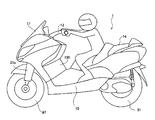
【解決手段】外部コントローラと、前記外部コントローラからの赤外線による制御信号を受信部1aで受信してその制御信号に基づいて遠隔制御される玩具本体とを備える玩具オートバイであって、前記玩具本体のハンドル12の前方には、赤外線を透過可能なウインドシールド11が設けられ、ウインドシールド11に被覆された部分に受信部1aが設けられていることを特徴とする。
【選択図】図2
A toy motorcycle capable of receiving a control signal from an external controller at a wide angle and having a good appearance is provided.
A toy motorcycle comprising an external controller and a toy main body that receives a control signal by infrared rays from the external controller at a receiving unit 1a and is remotely controlled based on the control signal. A windshield 11 capable of transmitting infrared rays is provided in front of the handle 12, and a receiving portion 1a is provided in a portion covered with the windshield 11.
[Selection] Figure 2

Description

本考案は、玩具オートバイに関するもので、さらに詳しくは、遠隔制御式の玩具オートバイにおける受信部の取付構造に関するものである。   The present invention relates to a toy motorcycle, and more particularly to a receiving unit mounting structure in a remotely controlled toy motorcycle.

遠隔制御式の玩具オートバイとしては、例えば、特許文献1に示すものがある。この特許文献1に開示されている玩具オートバイでは、コントローラからの制御信号を受信する受信部を荷台部の上に突出して設けている(例えば、特許文献1)。
特開2006−81814号公報(図12符号19参照)
As a remotely controlled toy motorcycle, for example, there is one shown in Patent Document 1. In the toy motorcycle disclosed in Patent Document 1, a receiving unit that receives a control signal from a controller is provided so as to protrude above the loading platform (for example, Patent Document 1).
Japanese Patent Laying-Open No. 2006-81814 (see reference numeral 19 in FIG. 12)

しかしながら、受信部を荷台部の上に突出して設けるとすれば、玩具オートバイが実物のオートバイとはかけ離れることになり、見栄えが悪いという問題がある。一方で、コントローラからの制御信号を広角で受信できる位置に受信部を設ける必要がある。   However, if the receiving unit is provided so as to protrude above the loading platform, there is a problem that the toy motorcycle is far from the real motorcycle and the appearance is poor. On the other hand, it is necessary to provide a receiving unit at a position where a control signal from the controller can be received at a wide angle.

本考案は、かかる問題点等に鑑みなされたもので、外部コントローラからの制御信号を広角で受信可能で、しかも、見栄えも良い玩具オートバイを提供することを目的とする。   The present invention has been made in view of such problems, and an object thereof is to provide a toy motorcycle that can receive a control signal from an external controller at a wide angle and has a good appearance.

請求項1の考案は、外部コントローラと、前記外部コントローラからの赤外線による制御信号を受信部で受信してその制御信号に基づいて遠隔制御される玩具本体とを備える玩具オートバイであって、前記玩具本体のハンドルの前方には、赤外線を透過可能なウインドシールドが設けられ、前記ウインドシールドに被覆された部分に前記受信部が設けられていることを特徴とする玩具オートバイである。
また、請求項2の考案は、請求項1に記載の玩具オートバイであって、前記ウインドシールドの内部又は内側に前記受信部が設けられていることを特徴とする。
また、請求項3の考案は、請求項1に記載の玩具オートバイであって、前記ウインドシールドによって前方及び上方を被覆された計器パネル相当部分に前記受信部が設けられていることを特徴とする。ここでの「計器パネル相当部分」とは、玩具オートバイにおける玩具本体は実物がモディファイされて計器パネルが省略されることも多いので、計器パネルが本来設けられる部分を指している。
The invention of claim 1 is a toy motorcycle comprising an external controller and a toy main body that receives a control signal by infrared rays from the external controller at a receiving unit and is remotely controlled based on the control signal. The toy motorcycle is characterized in that a windshield capable of transmitting infrared rays is provided in front of a handle of the main body, and the receiving portion is provided in a portion covered with the windshield.
The invention of claim 2 is the toy motorcycle according to claim 1, characterized in that the receiving section is provided inside or inside the windshield.
Further, the invention of claim 3 is the toy motorcycle according to claim 1, characterized in that the receiving portion is provided in a portion corresponding to an instrument panel covered forward and upward by the windshield. . The “instrument panel equivalent portion” here refers to a portion in which the instrument panel is originally provided because the toy body in the toy motorcycle is often modified and the instrument panel is omitted.

請求項4の考案は、請求項1又は3いずれか一項に記載の玩具用オートバイであって、前記ウインドシールドはスモークとなっていることを特徴とする。   The invention of claim 4 is the toy motorcycle according to claim 1, wherein the windshield is smoked.

請求項5の考案は、請求項1から4いずれか一項に記載の玩具オートバイであって、前記ハンドルの付け根部分とほぼ同一高さ位置に前記受信部が設けられていることを特徴とする。
また、請求項6の考案は、請求項1から4いずれか一項に記載の玩具オートバイであって、前記付け根部分よりも上方位置に前記受信部が設けられていることを特徴とする。
The invention of claim 5 is the toy motorcycle according to any one of claims 1 to 4, characterized in that the receiving portion is provided at substantially the same height as the base portion of the handle. .
A sixth aspect of the present invention is the toy motorcycle according to any one of the first to fourth aspects, wherein the receiving section is provided at a position higher than the base portion.

請求項7の考案は、請求項1から請求項6いずれか一項に記載の玩具用オートバイであって、前記玩具本体はスクータ型であることを特徴とする。   The invention of claim 7 is the toy motorcycle according to any one of claims 1 to 6, wherein the toy body is of a scooter type.

請求項1から7の考案によれば、受信部がウインドシールドによって被覆されているので、玩具本体の見栄えが悪くなることはない。特に、ウインドシールドの内部又は内側に受信部を設けるものでは受信部が外部から視認しにくいのでその効果は高い。また、計器パネル相当部分に受信部を設ける場合には、受信部を計器に見立てることができるので違和感が少ないものとなる。
また、請求項1から7の考案によれば、ウインドシールドは赤外線が透過可能となっているので、広角で制御信号が受信できることになる。
According to the first to seventh aspects of the present invention, since the receiving portion is covered with the windshield, the appearance of the toy body does not deteriorate. In particular, in the case where the receiving unit is provided inside or inside the windshield, the receiving unit is difficult to visually recognize from the outside, so that the effect is high. In addition, when the receiving unit is provided in a portion corresponding to the instrument panel, the receiving unit can be regarded as an instrument, so that a sense of incongruity is reduced.
According to the first to seventh aspects of the invention, since the windshield can transmit infrared rays, the control signal can be received at a wide angle.

請求項3の考案によれば、ウインドシールドがスモークとなっているので、外部から受信部がさらに視認しにくいものとなる。   According to the third aspect of the present invention, since the windshield is smoked, the receiving unit is more difficult to visually recognize from the outside.

請求項5及び請求項6の考案によれば、斜め上方からの制御信号がハンドルの付け根部分によって妨げられることが少なくなる。玩具本体は床面等のように外部コントローラよりも低い場所で走らせることが一般的であるからその効果は顕著である。   According to the invention of claim 5 and claim 6, it is less likely that the control signal from obliquely above is obstructed by the base portion of the handle. Since the toy body is generally run at a place lower than the external controller such as the floor surface, the effect is remarkable.

請求項7の考案によれば、スクータ型の玩具オートバイではクレードルが設けられるとともに、乗員(人形)と受信部とが比較的に離れることになるので、制御信号が特に受信しやすいものとなる。   According to the invention of claim 7, in the scooter type toy motorcycle, the cradle is provided and the occupant (doll) and the receiving unit are relatively separated from each other, so that the control signal is particularly easily received.

以下に、本考案に係る玩具オートバイを、図面を参照しながら説明する。
図1は、本考案に係る玩具本体を示した側面図、図2は、本考案に係る玩具本体の内部を概念的に示した側面図、図3は、操舵機構を示した斜視図、図4(A)〜(C)は、操舵機構の復帰動作を説明するための動作図、図5は、走行機構を示した概念的な断面図、図6はコントローラを示した斜視図である。
A toy motorcycle according to the present invention will be described below with reference to the drawings.
1 is a side view showing a toy main body according to the present invention, FIG. 2 is a side view conceptually showing the inside of the toy main body according to the present invention, and FIG. 3 is a perspective view showing a steering mechanism. 4 (A) to (C) are operation diagrams for explaining the return operation of the steering mechanism, FIG. 5 is a conceptual cross-sectional view showing the traveling mechanism, and FIG. 6 is a perspective view showing the controller.

玩具オートバイは、玩具本体1とコントローラ2(図6)とによって構成されている。そして、玩具本体1のボディ10には、操舵機構20(図3)及び走行機構30(図5)が搭載されている。   The toy motorcycle is composed of a toy body 1 and a controller 2 (FIG. 6). A steering mechanism 20 (FIG. 3) and a traveling mechanism 30 (FIG. 5) are mounted on the body 10 of the toy body 1.

ボディ10は、スクータを模擬的に形作るもので、透光性ウインドシールド11及びハンドル12等が取り付けられている前部10aと、乗員人形の脚部を受け入れるクレードル13が形成されている中間部10bと、シート14が形成されている後部10cとから構成されている。このボディ10は、左右に2分割され、内部に、操舵機構20(図3参照)及び走行機構30(図5参照)が収容される。   The body 10 simulates a scooter, and includes a front portion 10a to which a translucent windshield 11 and a handle 12 are attached, and an intermediate portion 10b in which a cradle 13 for receiving a leg portion of an occupant doll is formed. And a rear portion 10c on which the sheet 14 is formed. The body 10 is divided into left and right parts, and a steering mechanism 20 (see FIG. 3) and a traveling mechanism 30 (see FIG. 5) are housed inside.

操舵機構20は、図3に示すように、(1)後面に作動軸21aが取り付けられたフォーク支持部材21と、(2)ボディ10に一体的に係止され、作動軸21aが挿通される孔22aを有し、後面下部に突起22bが形成された作動軸支持部材22と、(3)作動軸21aに巻回される捩じりコイルスプリング23と、(4)作動軸21aの後端部がきつく嵌合される孔24aが一端に形成され、後面周縁にギヤ24bが形成され、前面に突起24cが形成されたセクタギヤ24と、(5)操舵用モータ25と、モータ軸に固設され、セレクタギヤ24のギヤ24bに噛合するピニオン26と、によって構成されている。これに操舵機構20はクレードル13の前方のフロントカウリング100に収納されている。   As shown in FIG. 3, the steering mechanism 20 includes (1) a fork support member 21 having an operating shaft 21a attached to the rear surface, and (2) an integral locking with the body 10, and the operating shaft 21a is inserted therethrough. An operating shaft support member 22 having a hole 22a and having a protrusion 22b formed at the lower part of the rear surface; (3) a torsion coil spring 23 wound around the operating shaft 21a; and (4) a rear end of the operating shaft 21a. A sector gear 24 having a hole 24a into which the portion is tightly fitted is formed at one end, a gear 24b is formed at the peripheral edge of the rear surface, and a projection 24c is formed on the front surface, (5) a steering motor 25, and a motor shaft The pinion 26 meshes with the gear 24b of the selector gear 24. The steering mechanism 20 is housed in the front cowling 100 in front of the cradle 13.

フォーク支持部材21には、図2及び図3に示すように、車体の前後方向に傾斜する軸線Aを持つ孔21bが形成され、該孔21bにフォーク21cのフォーク軸21dが軸線Aを中心に回動自在に支持されている。このフォーク21cの下端部には、前輪27が回転自在に支持されている。   2 and 3, the fork support member 21 is formed with a hole 21b having an axis A inclined in the front-rear direction of the vehicle body. The fork shaft 21d of the fork 21c is centered on the axis A in the hole 21b. It is supported rotatably. A front wheel 27 is rotatably supported at the lower end of the fork 21c.

作動軸21aは、図2及び図3に示すように、車体の前後方向に水平に延びる軸線Bを持つように設置されている。この作動軸21aは、作動軸支持部材22の孔22aに挿通され、作動軸支持部材22の後面から突出している。この作動軸21aの突出部分には、ねじりコイルスプリング23の巻回部が嵌合され、作動軸21aの後端部はセクタギヤ24の孔24aにきつく嵌合されている。   As shown in FIGS. 2 and 3, the operating shaft 21a is installed so as to have an axis B extending horizontally in the front-rear direction of the vehicle body. The operation shaft 21 a is inserted into the hole 22 a of the operation shaft support member 22 and protrudes from the rear surface of the operation shaft support member 22. A winding portion of the torsion coil spring 23 is fitted to the protruding portion of the operating shaft 21a, and the rear end portion of the operating shaft 21a is tightly fitted to the hole 24a of the sector gear 24.

操舵用モータ25は、正逆回転可能な直流モータである。この操舵用モータ25は、モータ軸が鉛直軸方向に延在するようにボディ10の中間部10bの下部に設置されている。   The steering motor 25 is a DC motor that can rotate forward and backward. The steering motor 25 is installed in the lower part of the intermediate portion 10b of the body 10 so that the motor shaft extends in the vertical axis direction.

このように構成された操舵機構20においては、操舵用モータ25の非作動時には、図4(A)に示すように、作動軸支持部材22の突起22bとセクタギヤ24の突起24cとが捩じりコイルスプリング23のアーム部23a,23bで挟持された状態にあり、セクタギア24は中立位置に保持される。この位置が請求項1に言う作動軸21aの「所定回動位置」である。   In the steering mechanism 20 configured as described above, when the steering motor 25 is not operated, the protrusion 22b of the operating shaft support member 22 and the protrusion 24c of the sector gear 24 are twisted as shown in FIG. The sector gear 24 is held between the arm portions 23a and 23b of the coil spring 23, and the sector gear 24 is held at the neutral position. This position is the “predetermined rotational position” of the operating shaft 21a according to claim 1.

この状態から、操舵用モータ25によってピニオン26が回転(回動)されると、図4(B)又は図4(C)に示すように、ピニオン26の回転(回動)方向に応じてセクタギヤ24が時計方向又は反時計方向に回動される。そして、このセクタギア24に追従して作動軸21aが回動され、その回動方向に応じてフォーク支持部材21が作動軸21aの軸線Bを中心に回動される。その結果、フォーク21cひいては前輪27が傾動し、その傾動方向に応じて前輪27が車体の左方向又は右方向に操舵される。   From this state, when the pinion 26 is rotated (turned) by the steering motor 25, as shown in FIG. 4B or FIG. 4C, the sector gear according to the rotation (turning) direction of the pinion 26. 24 is rotated clockwise or counterclockwise. Then, the operating shaft 21a is rotated following the sector gear 24, and the fork support member 21 is rotated around the axis B of the operating shaft 21a according to the rotating direction. As a result, the fork 21c and thus the front wheel 27 tilt, and the front wheel 27 is steered leftward or rightward of the vehicle body according to the tilting direction.

なお、操舵用モータ25の回転駆動され、セクタギヤ24が中立位置から偏倚すると、図4(B)又は図4(C)に示すように、突起22bによってコイルスプリング23のアーム部23a,23bの一方が係止された状態で、突起24cによってアーム部23a,23bの他方が捩じりコイルスプリング23の付勢力に抗して拡げられる。一方、操舵用モータ25の回転駆動が解除されると、捩じりコイルスプリング23の付勢力によって、セクタギヤ24は、元の状態(中立位置)に復帰され、それに伴って、前輪27も中立位置(真直ぐな状態)に戻される。   When the steering motor 25 is driven to rotate and the sector gear 24 deviates from the neutral position, as shown in FIG. 4B or 4C, one of the arm portions 23a and 23b of the coil spring 23 is caused by the projection 22b. Is locked, the other of the arm portions 23a and 23b is expanded against the urging force of the torsion coil spring 23 by the projection 24c. On the other hand, when the rotational drive of the steering motor 25 is released, the sector gear 24 is returned to the original state (neutral position) by the urging force of the torsion coil spring 23. Accordingly, the front wheel 27 is also in the neutral position. It is returned to (straight state).

走行機構30は、後輪31を駆動するためのものである。後輪31は、図2に示すように、ボディ10の後部10cの下部に回転可能に支持される。この後輪31は、図5に示すように、内部を中空にしたプラスチック製のホイール31aと、このホイール31aの外周に装着したタイヤ31bと、ホイール31aの回転中心部の左右外方へ突出して設けられた一対の中空のボス31c,31cとを有している。また、ホイール31aの内部には、フライホイール32が収容され、その回転中心には、軸32aが設けられている。そして、この軸32aの端部は、ボス31c,31cを貫通し、さらに、ボディ10の両サイドメンバ10d,10eに回転自在に挿嵌されている。
ここで、フライホイール32は、ジャイロ的作用により玩具オートバイ自体の走行姿勢を安定化させるものであり、後輪31の内部に収納し得る径と厚さを有する金属材から構成されている。
The traveling mechanism 30 is for driving the rear wheel 31. As shown in FIG. 2, the rear wheel 31 is rotatably supported by the lower portion of the rear portion 10 c of the body 10. As shown in FIG. 5, the rear wheel 31 protrudes left and right outward from a plastic wheel 31a having a hollow inside, a tire 31b attached to the outer periphery of the wheel 31a, and a rotation center portion of the wheel 31a. It has a pair of hollow bosses 31c, 31c provided. A flywheel 32 is housed inside the wheel 31a, and a shaft 32a is provided at the center of rotation. The end portion of the shaft 32a penetrates the bosses 31c and 31c, and is further rotatably inserted into both side members 10d and 10e of the body 10.
Here, the flywheel 32 stabilizes the running posture of the toy motorcycle itself by a gyroscopic action, and is made of a metal material having a diameter and a thickness that can be accommodated in the rear wheel 31.

この走行機構30は、ホイール31aを駆動させる機構と、フライホイール32を駆動させる機構とを含んで構成されている。そして、この走行機構30は、後輪31を走行に適した速度で回転駆動するとともにフライホイール32を後輪31の回転速度より十分に速い速度で回転駆動してジャイロ的効果を生じさせる。   The traveling mechanism 30 includes a mechanism that drives the wheel 31 a and a mechanism that drives the flywheel 32. The traveling mechanism 30 rotationally drives the rear wheel 31 at a speed suitable for traveling and rotationally drives the flywheel 32 at a speed sufficiently higher than the rotational speed of the rear wheel 31 to generate a gyro effect.

まず、フライホイール31aを駆動させる機構を説明すれば、この機構は、ボディ10の中間部10bに装着された走行用モータ33のモータ軸に固着されたピニオン34と、ボディ10のサイドメンバ10eに設けられた軸35に回転自在に支持されたアイドルギヤ36aである大径ギヤ36aと、アイドルギヤ36であり大径ギヤ36aと一体的に回転する小径ギヤ36bと、摩擦クラッチ板37を介してホイール31aに回転自在に添設された従動ギヤ38とから構成されている。   First, a mechanism for driving the flywheel 31 a will be described. This mechanism is connected to the pinion 34 fixed to the motor shaft of the traveling motor 33 attached to the intermediate portion 10 b of the body 10 and the side member 10 e of the body 10. A large-diameter gear 36 a that is an idle gear 36 a rotatably supported on a shaft 35 provided, a small-diameter gear 36 b that is an idle gear 36 and rotates integrally with the large-diameter gear 36 a, and a friction clutch plate 37. The driven gear 38 is rotatably attached to the wheel 31a.

次に、フライホイール32を駆動させる機構を説明すれば、この機構は、ピニオン34と、大径ギヤ36aと、小径ギヤ36aと、従動32bとから構成されている。
これにより、走行用モータ33から後輪31への動力伝達は、ピニオン34、大径ギヤ36a、小径ギヤ36b、従動ギヤ38及び摩擦クラッチ板37を介して行われ、走行モータ33からフライホイール32への動力伝達は、ピニオン34、大径ギヤ36a、小径ギヤ36a及び従動ギヤ32bを介して行われる。
Next, a mechanism for driving the flywheel 32 will be described. The mechanism includes a pinion 34, a large-diameter gear 36a, a small-diameter gear 36a, and a driven 32b.
Thus, power transmission from the traveling motor 33 to the rear wheel 31 is performed via the pinion 34, the large diameter gear 36a, the small diameter gear 36b, the driven gear 38, and the friction clutch plate 37, and from the traveling motor 33 to the flywheel 32. The power transmission to is performed through the pinion 34, the large diameter gear 36a, the small diameter gear 36a, and the driven gear 32b.

この玩具オートバイでは、図示しない電源スイッチが、玩具本体1に配設されており、電源スイッチが操作されると、走行用モータ33が駆動される。走行用モータ33が駆動されると、ピニオン34,アイドルギヤ36が回転される。そして、アイドルギヤ36が回転されると、大径ギヤ36a,従動ギヤ32bを介して軸32aが回転され、それによってフライホイール32が回転され、また、小径ギヤ36b,従動ギヤ38,クラッチ板37を介して後輪31が回転される。   In this toy motorcycle, a power switch (not shown) is disposed in the toy main body 1, and when the power switch is operated, the traveling motor 33 is driven. When the traveling motor 33 is driven, the pinion 34 and the idle gear 36 are rotated. When the idle gear 36 is rotated, the shaft 32a is rotated via the large diameter gear 36a and the driven gear 32b, whereby the flywheel 32 is rotated, and the small diameter gear 36b, the driven gear 38, and the clutch plate 37 are rotated. , The rear wheel 31 is rotated.

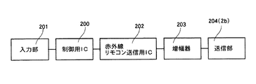
コントローラ2は、図6に示すように、操舵用モータ25の制御用ボタン2a、赤外線LED2b、電源ボタン2cを備えている。このコントローラ2には、制御用IC200,入力部201,赤外線リモコン送信用IC202,増幅器203及び送信部204(赤外線LED2b)を備えている(図7参照)。なお、図示していないが、コントローラ2には、電源である電池が組み込まれている。   As shown in FIG. 6, the controller 2 includes a control button 2a for the steering motor 25, an infrared LED 2b, and a power button 2c. The controller 2 includes a control IC 200, an input unit 201, an infrared remote control transmission IC 202, an amplifier 203, and a transmission unit 204 (infrared LED 2b) (see FIG. 7). Although not shown, the controller 2 incorporates a battery as a power source.

ここで、入力部201は、操舵用モータ25の制御ボタン2aによって構成されている。この制御ボタン2aは、矢印で示す周方向の一端部を押し込むことによって、操舵用モータ25を一方に回転させ、他端部を押し込むことによって、操舵用モータ25を他方に回転させる。
制御用IC200は、入力部201から入力された操作情報に基づいて制御データを生成する。赤外線リモコン送信用IC202は、制御用IC200で生成された制御データを一定の規則に従って符号化するとともに変調する。そして、増幅器203は赤外線リモコン送信用IC202で変調された制御データを増幅し、送信部204は増幅器で増幅された制御データを玩具本体1に向けて送信する。
Here, the input unit 201 is configured by a control button 2 a of the steering motor 25. The control button 2a rotates the steering motor 25 in one direction by pushing in one end portion in the circumferential direction indicated by an arrow, and rotates the steering motor 25 in the other direction by pushing in the other end portion.
The control IC 200 generates control data based on the operation information input from the input unit 201. The infrared remote control transmission IC 202 encodes and modulates the control data generated by the control IC 200 according to a certain rule. The amplifier 203 amplifies the control data modulated by the infrared remote control transmission IC 202, and the transmission unit 204 transmits the control data amplified by the amplifier toward the toy body 1.

一方、玩具本体1には、赤外線センサモジュール300a,赤外線リモコン受信用IC300b,制御用IC301,モータ駆動部302を備えている(図8参照)。
赤外線センサモジュール300aは、赤外線制御データを受信するフォトダイオード又はフォトトランジスタ等の赤外線受信部1aと、受信部で受信した赤外線制御データを増幅する増幅部と、増幅部で増幅された赤外線制御データを検波する検波部とを備える。赤外線センサモジュール300aは一つのチップで構成されていても良い。
この赤外線センサモジュール300aの赤外線受信部1aは、ウインドシールド11の内部においてハンドル12の付け根部分とほぼ同じ高さ位置に設けられている。この構造は、ウインドシールド11を左右又は前後で分割した二つのパーツで構成し、この二つのパーツを結合してできる中空部に赤外線センサモジュール300aを設置したり、ウインドシールド11に凹部を形成しておき、この凹部に赤外線センサモジュール300aを設置した後、その凹部開口を赤外線が透過可能な部材で閉塞することなどによって実現される。
なお、ウインドシールド11によって前方及び上方を被覆された計器パネル相当部分が存在する場合には、赤外線センサモジュール300aの赤外線受信部1aをその計器パネル相当部分に設けることもできる。
赤外線リモコン受信用IC300bは、検波部で検波された赤外線制御データを一時的に格納するレジスタと、制御クロックを発生するクロック発生部と、一定の方式に従って符号化されたデータ(エンコードされたデータ)を復元する復調するデコーダとを備えている。
制御用IC301は、玩具本体1の中間部下部に設置された基板1cに搭載され、図示しないCPU,ROM及びRAMを含んで構成されている。そして、制御用IC301は、コントローラ2の送信部204から受信した制御データをRAMに格納し、ROMのプログラムに応じて玩具本体1の操舵用モータ25を制御する。モータ駆動部302は制御用IC301の指令に従って操舵用モータ25の正逆転駆動を行う。なお、基板1cの下方には、蓄電池等の電源1dが設置されている。
On the other hand, the toy body 1 includes an infrared sensor module 300a, an infrared remote control receiving IC 300b, a control IC 301, and a motor driving unit 302 (see FIG. 8).
The infrared sensor module 300a includes an infrared receiver 1a such as a photodiode or phototransistor that receives infrared control data, an amplifier that amplifies infrared control data received by the receiver, and infrared control data amplified by the amplifier. And a detection unit for detecting. The infrared sensor module 300a may be composed of a single chip.
The infrared receiver 1a of the infrared sensor module 300a is provided in the windshield 11 at substantially the same height as the base portion of the handle 12. In this structure, the windshield 11 is composed of two parts divided into left and right or front and rear, and the infrared sensor module 300a is installed in a hollow part formed by joining these two parts, or a recess is formed in the windshield 11. In addition, after the infrared sensor module 300a is installed in the recess, the opening of the recess is closed with a member that can transmit infrared rays.
In addition, when there exists an instrument panel equivalent part covered front and upper by the windshield 11, the infrared receiving part 1a of the infrared sensor module 300a can also be provided in the instrument panel equivalent part.
The infrared remote control receiving IC 300b includes a register that temporarily stores infrared control data detected by the detection unit, a clock generation unit that generates a control clock, and data encoded according to a certain method (encoded data). And a decoder for demodulating the signal.
The control IC 301 is mounted on a substrate 1c installed at the lower part of the middle part of the toy body 1, and includes a CPU, a ROM, and a RAM (not shown). The control IC 301 stores the control data received from the transmission unit 204 of the controller 2 in the RAM, and controls the steering motor 25 of the toy main body 1 according to the program in the ROM. The motor driving unit 302 performs forward / reverse driving of the steering motor 25 in accordance with a command from the control IC 301. A power source 1d such as a storage battery is installed below the substrate 1c.

このように構成された玩具オートバイでは、玩具本体1の図示しない電源を入れると、走行用モータ33が作動され、後輪31及びフライホイール32が回転される。
そこで、玩具本体1を床等に置くと、該玩具本体1は直進する。
ここで、コントローラ2の制御ボタン2aを操作すると、玩具本体1の操舵用モータ25が駆動され、それによって、前輪27が左又は右に旋回される。そして、制御ボタン2aの操作を止めると、操舵用モータ25は停止し、それに伴って、捩じりコイルスプリング23の付勢力によって、前輪27が中立位置に復帰される。
In the toy motorcycle configured as described above, when the toy main body 1 is turned on (not shown), the traveling motor 33 is operated, and the rear wheel 31 and the flywheel 32 are rotated.
Therefore, when the toy body 1 is placed on the floor or the like, the toy body 1 goes straight.
Here, when the control button 2a of the controller 2 is operated, the steering motor 25 of the toy body 1 is driven, whereby the front wheel 27 is turned left or right. When the operation of the control button 2 a is stopped, the steering motor 25 is stopped, and accordingly, the front wheel 27 is returned to the neutral position by the urging force of the torsion coil spring 23.

本考案に係る玩具本体を示した側面図である。It is the side view which showed the toy main body which concerns on this invention. 本考案に係る玩具本体の内部を概念的に示した側面図である。It is the side view which showed notionally the inside of the toy main body concerning this invention. 操舵機構を示した斜視図である。It is the perspective view which showed the steering mechanism. (A)〜(C)は、操舵機構の復帰動作を説明するための動作図である。(A)-(C) is an operation figure for explaining return operation of a steering mechanism. 走行機構を示した概念的な断面図である。It is a conceptual sectional view showing a traveling mechanism. コントローラを示した斜視図である。It is the perspective view which showed the controller. コントローラの回路構成を示すブロック図である。It is a block diagram which shows the circuit structure of a controller. 玩具本体の回路構成を示すブロック図である。It is a block diagram which shows the circuit structure of a toy main body.

符号の説明Explanation of symbols

1 玩具本体
1a 赤外線受信部
2 コントローラ
10 ボディ
11 ウインドシールド
12 ハンドル
DESCRIPTION OF SYMBOLS 1 Toy main body 1a Infrared receiver 2 Controller 10 Body 11 Windshield 12 Handle

Claims (7)

外部コントローラと、前記外部コントローラからの赤外線による制御信号を受信部で受信してその制御信号に基づいて遠隔制御される玩具本体とを備える玩具オートバイであって、前記玩具本体のハンドルの前方には、赤外線を透過可能なウインドシールドが設けられ、前記ウインドシールドに被覆された部分に前記受信部が設けられていることを特徴とする玩具オートバイ。   A toy motorcycle comprising an external controller and a toy main body that receives a control signal by infrared rays from the external controller and is remotely controlled based on the control signal, in front of the handle of the toy main body A toy motorcycle characterized in that a windshield capable of transmitting infrared rays is provided, and the receiving portion is provided in a portion covered by the windshield. 前記ウインドシールドの内部又は内側に前記受信部が設けられていることを特徴とする請求項1に記載の玩具オートバイ。   The toy motorcycle according to claim 1, wherein the receiving unit is provided inside or inside the windshield. 前記ウインドシールドによって前方及び上方を被覆された計器パネル相当部分に前記受信部が設けられていることを特徴とする請求項1に記載の玩具オートバイ。   2. The toy motorcycle according to claim 1, wherein the receiving portion is provided in a portion corresponding to an instrument panel covered forward and upward by the windshield. 前記ウインドシールドはスモークとなっていることを特徴とする請求項1から3いずれか一項に記載の玩具オートバイ。   The toy motorcycle according to any one of claims 1 to 3, wherein the windshield is smoked. 前記ハンドルの付け根部分とほぼ同一高さ位置に前記受信部が設けられていることを特徴とする請求項1から4いずれか一項に記載の玩具オートバイ。   The toy motorcycle according to any one of claims 1 to 4, wherein the receiving unit is provided at a height position substantially the same as a base portion of the handle. 前記付け根部分よりも上方位置に前記受信部が設けられていることを特徴とする請求項1から4いずれか一項に記載の玩具オートバイ。   The toy motorcycle according to any one of claims 1 to 4, wherein the receiving unit is provided at a position above the base portion. 前記玩具本体はスクータ型であることを特徴とする請求項1から請求項6いずれか一項に記載の玩具オートバイ。   The toy motorcycle according to any one of claims 1 to 6, wherein the toy main body is of a scooter type.
JP2008004114U 2008-06-18 2008-06-18 Toy motorcycle Expired - Fee Related JP3144435U (en)

Priority Applications (1)

Application Number Priority Date Filing Date Title
JP2008004114U JP3144435U (en) 2008-06-18 2008-06-18 Toy motorcycle

Applications Claiming Priority (1)

Application Number Priority Date Filing Date Title
JP2008004114U JP3144435U (en) 2008-06-18 2008-06-18 Toy motorcycle

Publications (1)

Publication Number Publication Date
JP3144435U true JP3144435U (en) 2008-08-28

Family

ID=43294296

Family Applications (1)

Application Number Title Priority Date Filing Date
JP2008004114U Expired - Fee Related JP3144435U (en) 2008-06-18 2008-06-18 Toy motorcycle

Country Status (1)

Country Link
JP (1) JP3144435U (en)

Similar Documents

Publication Publication Date Title
JP3005204B2 (en) Bicycle motor control device
TW449559B (en) Magnetically operated bicycle antitheft device
JP3231006B2 (en) Gear change control device for bicycle
JP5721256B2 (en) Control device for electric vehicle
JP5070367B2 (en) Electric bicycle
JP2005239124A (en) Speed reduction gear device for bicycle
TW200410858A (en) Bicycle computer control arrangement and method
JPH11239674A (en) Controller for game machine
US20170184194A1 (en) Vehicle shift system
JP2009101127A (en) Control device for steering running toy and running toy
KR20140046282A (en) Pedal storage device for vehicle
JP3144435U (en) Toy motorcycle
JP3144434U (en) Toy motorcycle
JP6249339B2 (en) Wind-up toy
JP2942512B2 (en) Bicycle anti-theft device, internal transmission, and transmission system
JP4969394B2 (en) Car toy
JP2009261592A (en) Running toy
ATE356743T1 (en) BICYCLE HUB WITH ANTI-THEFT MECHANISM
JP7490393B2 (en) Propulsion system for human-powered vehicle and control device for human-powered vehicle
JP4997094B2 (en) Riding simulator
JP2003320943A (en) Transmission ratio variable steering apparatus
JP2006335284A (en) Steering device for vehicle
JP3305681B2 (en) Bicycle anti-theft control device, key and anti-theft system
KR101810401B1 (en) Locking Device for Electric Bicycle
WO2016136809A1 (en) Electric one-wheel motorcycle

Legal Events

Date Code Title Description
R150 Certificate of patent or registration of utility model

Free format text: JAPANESE INTERMEDIATE CODE: R150

FPAY Renewal fee payment (event date is renewal date of database)

Free format text: PAYMENT UNTIL: 20110806

Year of fee payment: 3

A624 Registrability report (other person)

Free format text: JAPANESE INTERMEDIATE CODE: A624

Effective date: 20090319

LAPS Cancellation because of no payment of annual fees