JP3140639U - Reflector for lighting device - Google Patents
Reflector for lighting device Download PDFInfo
- Publication number
- JP3140639U JP3140639U JP2008000288U JP2008000288U JP3140639U JP 3140639 U JP3140639 U JP 3140639U JP 2008000288 U JP2008000288 U JP 2008000288U JP 2008000288 U JP2008000288 U JP 2008000288U JP 3140639 U JP3140639 U JP 3140639U
- Authority
- JP
- Japan
- Prior art keywords
- reflector
- lighting device
- light source
- parabolic
- parabolic column
- Prior art date
- Legal status (The legal status is an assumption and is not a legal conclusion. Google has not performed a legal analysis and makes no representation as to the accuracy of the status listed.)
- Expired - Fee Related
Links
Images


Landscapes
- Optical Elements Other Than Lenses (AREA)
- Planar Illumination Modules (AREA)
Abstract
【課題】陰極管等の線光源からの発光を、求められた方向に効率よく反射し、且つ優れた製造コストを有する照明装置用反射体および該照明装置用反射体を備えた照明装置を提供することを目的とする。
【解決手段】発泡プラスチック製の反射体に溝を形成し、溝の壁面の形状を放物柱面として、該放物柱面の壁面の焦点の位置に冷陰極線管、外部電極式放電管等の線光源を設置すると、光源から放射された光は放物柱壁面に反射して効率的な反射光線となるような照明装置用反射体および、該反射体を備えた照明装置を構成する。
【選択図】図1
Provided are a reflector for a lighting device that efficiently reflects light emitted from a line light source such as a cathode tube in a required direction and has an excellent manufacturing cost, and a lighting device including the reflector for a lighting device. The purpose is to do.
A groove is formed in a reflector made of foamed plastic, the shape of the wall surface of the groove is a parabolic column surface, and a cold cathode ray tube, an external electrode type discharge tube or the like is located at the focal point of the wall surface of the parabolic column surface. When the linear light source is installed, the light emitted from the light source is reflected on the parabolic column wall surface and becomes an efficient reflected light beam, and an illumination device including the reflector is configured.
[Selection] Figure 1
Description
本考案は、照明装置に使用される反射体と該反射体を備えた照明装置に関する。 The present invention relates to a reflector used in a lighting device and a lighting device including the reflector.
近年、地球上の資源を有効に使用するために、機器の省電力化が求められている。特に照明装置においては、発光効率が問題となる。光源に関しては蛍光灯、陰極線菅、外部電極式放電管等のように発光効率の優れたものが開発されている。 In recent years, in order to effectively use resources on the earth, power saving of devices has been demanded. Particularly in a lighting device, the luminous efficiency becomes a problem. As the light source, a light source having excellent luminous efficiency such as a fluorescent lamp, a cathode ray tube, an external electrode type discharge tube has been developed.
しかし、光源の発光効率が優れていても、発光された光を有効に利用できないと、全体として省資源、高効率化を実現できない。具体的には、同じ発光効率を有する光源を使用しても、反射効率が悪い反射体や、反射光を求められる方向に反射することが困難な反射体を用いると、照明装置全体としての照明効率を向上させることができない。特に、光源として冷陰極線管、外部電極式放電管のような線光源を複数並列に配置した所謂面光源の照明装置において、反射光を有効に制御し得る反射体であって、安価な材料で製造できるものは見当たらない。 However, even if the light emission efficiency of the light source is excellent, resource saving and high efficiency cannot be realized as a whole unless the emitted light can be used effectively. Specifically, when a light source having the same luminous efficiency is used and a reflector with poor reflection efficiency or a reflector that is difficult to reflect reflected light in the required direction is used, the illumination device as a whole is illuminated. The efficiency cannot be improved. In particular, in a so-called surface light source illuminating device in which a plurality of linear light sources such as cold cathode ray tubes and external electrode type discharge tubes are arranged in parallel as a light source, it is a reflector that can effectively control reflected light, and is made of an inexpensive material. I can't find anything that can be manufactured.
考案者らは、発泡プラスチックに放物線状の溝を設けて、その焦点付近に細い線状の発光光源を配置すると、予想以上に優れた平行光線が得られることを発見した。当初は、発泡プラスチックの表面には凹凸があり、このように優れた平行光線は得られないだろうという先入観があった。しかし、実際には、予想以上の高品質の平行光線が得られた。 The inventors have found that if a parabolic groove is provided in a foamed plastic, and a thin linear light-emitting light source is arranged near the focal point, a parallel beam superior to that expected can be obtained. Initially, there was a preconception that the surface of the foamed plastic had irregularities, and such an excellent parallel beam could not be obtained. In practice, however, a higher quality parallel beam than expected was obtained.
そこで、本考案は、光源からの光を、求められた方向に効率よく反射し、且つ優れた製造コストを有する照明装置用反射体および該反射体を備えた照明装置を提供することを目的とする。 Therefore, the present invention aims to provide a reflector for a lighting device that efficiently reflects light from a light source in a required direction and has an excellent manufacturing cost, and a lighting device including the reflector. To do.
請求項1に記載の考案は、照明装置に用いる照明装置用反射体であって、
壁面の形状が放物柱面となる溝(以下「放物柱面溝」ともいう)を有して、前記形状が放物柱面の壁面(以下「放物柱壁面」ともいう)の焦点の位置に線光源を設置すると、前記線光源からの発光は前記放物柱壁面に反射して平行光線となることを特徴とする。
The device according to claim 1 is a reflector for a lighting device used in a lighting device,
The focal point of the wall whose surface is a parabolic column surface (hereinafter also referred to as “parabolic column surface groove”) and whose shape is a parabolic column surface (hereinafter also referred to as “parabolic column wall”). When a line light source is installed at the position of, light emitted from the line light source is reflected on the parabolic column wall surface to become parallel rays.
請求項2に記載の考案は、請求項1に記載の照明装置用反射体に係り、
照明装置用反射体の材料は発泡プラスチックであることを特徴とする。
The device according to claim 2 relates to the reflector for lighting device according to claim 1,
The material for the reflector for the lighting device is a foamed plastic.
発泡プラスチックは軽量であり、低コスト、軽量という長所を持ちながら無表面処理でも実用に耐える反射効率がある。 Foamed plastic is lightweight and has the advantages of low cost and light weight, yet has a reflection efficiency that can withstand practical use even without surface treatment.
請求項3に記載の考案は、請求項1に記載の照明装置用反射体に係り、
前記放物柱面溝は、金属板またはプラスチック板を湾曲させて製造することを特徴とする。
The device according to claim 3 relates to the reflector for lighting device according to claim 1,
The parabolic column surface groove is manufactured by curving a metal plate or a plastic plate.
請求項4に記載の考案は、請求項1乃至3のいずれかに記載の照明装置用反射体に係り、
前記溝は複数並列に設置されていることを特徴とする。
The device according to claim 4 relates to the reflector for lighting device according to any one of claims 1 to 3,
A plurality of the grooves are arranged in parallel.
請求項5に記載の考案は、請求項1乃至4のいずれかに記載の照明装置用反射体に係り、
前記線光源は小径の冷陰極線管または外部電極式放電管であることを特徴とする。
The device according to claim 5 relates to the reflector for lighting device according to any one of claims 1 to 4,
The line light source is a small-diameter cold cathode ray tube or an external electrode type discharge tube.
請求項6に記載の考案は、照明装置であって、
請求項1乃至5のいずれかに記載の照明装置用反射体を備えていることを特徴とする。
The invention according to claim 6 is a lighting device,
It has the reflector for lighting devices in any one of Claims 1 thru | or 5, It is characterized by the above-mentioned.
本照明装置用反射体を備えることにより、薄型でありながら面全体に渡って均一な光の照射を効率よく行える照明装置を製造できる。 By including the reflector for the illumination device, it is possible to manufacture an illumination device that can efficiently irradiate uniform light over the entire surface while being thin.
請求項7に記載の考案は、液晶表示装置のバックライト装置であって、
請求項1乃至5のいずれかに記載の照明装置用反射体を備えていることを特徴とする。
The device according to claim 7 is a backlight device of a liquid crystal display device,
It has the reflector for lighting devices in any one of Claims 1 thru | or 5, It is characterized by the above-mentioned.
本照明装置用反射体を備えることにより、薄型でありながら面全体に渡って均一な光の照射を効率よく行える液晶表示装置のバックライト装置を製造できる。 By providing the reflector for the illumination device, it is possible to manufacture a backlight device for a liquid crystal display device that is thin and can efficiently irradiate uniform light over the entire surface.
本考案にかかる照明装置用反射体によれば、光源からの光を所望の方向へ均一な平行光線として、反射させることができ、効率的な照明装置を実現できる。また特に、発泡プラスチックは非常に軽量であり、加えて加工も容易であることにより、広範囲な応用ができる。多数の本考案にかかる照明装置用反射体を並列配置とすることにより、面全体に均一な照射を行える。理想的な放物線形状を実現できるので反射効率を高くできる。 According to the reflector for an illumination device according to the present invention, the light from the light source can be reflected as a uniform parallel light beam in a desired direction, and an efficient illumination device can be realized. In particular, foamed plastics are very lightweight and can be easily processed, so that they can be used in a wide range of applications. By arranging a large number of reflectors for an illumination device according to the present invention in parallel, uniform irradiation can be performed on the entire surface. Since an ideal parabolic shape can be realized, the reflection efficiency can be increased.
以下、図を参照しつつ、本考案を実施するための形態につき説明する。
(実施の形態1)
Hereinafter, embodiments for carrying out the present invention will be described with reference to the drawings.
(Embodiment 1)
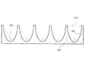
図1は本考案の実施の形態1に係る照明装置用反射体の構成の概略を示す側面図である。 FIG. 1 is a side view showing an outline of the configuration of a reflector for an illumination device according to Embodiment 1 of the present invention.
図1において、103は照明装置用反射体であり、115は放物柱面溝であり、105は放物柱壁面である。また114は放物柱壁面105の焦点の位置であり、光源を設置する位置である。照明装置用反射体103は発泡プラスチックにより形成する。発泡プラスチックは安価であるとともに、加工が容易であり、放物柱面の形状を有する溝105を低コストで作成できる。照明装置用反射体103には切断面が放物線となる前記放物柱面溝105が1個以上形成されている。これら複数の放物柱面溝は目的に応じて配置ピッチを
変えたり、放物線の広がり形状を変えたりしてもよい。
In FIG. 1, 103 is a reflector for a lighting device, 115 is a parabolic column surface groove, and 105 is a parabolic column wall surface.
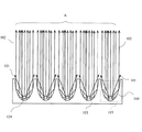
図2は図1の放物柱壁面105の焦点の位置114に、線光源を設置した場合の光線の方向の概略を示す側面図である。
FIG. 2 is a side view showing an outline of the direction of light rays when a line light source is installed at the
図2において、124は焦点の位置114に設置された線光源である。102は線光源124からの発光した光のうち照明装置用反射体に反射してお互いに平行な方向へ反射された光線である。101は線光源124からの発光した光のうち照明装置用反射体に反射しないで、放射される光線である。放物柱壁面105は形状が放物線形状であるので、線光源124が放物線の焦点の位置に設置されると、線光源124から照射され、放物面105に入射した反射光はお互いに平行な光線102となる。Aは平行光線102の集合である。
発泡プラスチックの表面は平坦ではないので、効率的に反射光線を得ることは困難であるとの先入観があったが、実際には実用に耐える反射光線を得ることができた。
In FIG. 2, a
Since the surface of the foamed plastic was not flat, there was a preconception that it was difficult to obtain reflected light efficiently, but in practice, a reflected light that could withstand practical use could be obtained.
また、発泡プラスチックは重量が小さいので、発泡プラスチックを材料とする照明装置用反射体を照明装置に使用すると軽量な照明装置を作成できる。さらに、照明装置は天井等に吊るす場合が多いので軽量であることは重要である。
(実施の形態2)
図3は本考案の実施の形態2に係る照明装置用反射体の構成の概略を示す側面図である。
In addition, since the foamed plastic has a small weight, when a reflector for a lighting device made of foamed plastic is used for the lighting device, a lightweight lighting device can be created. Furthermore, since the lighting device is often hung on the ceiling or the like, it is important that the lighting device is lightweight.
(Embodiment 2)
FIG. 3 is a side view showing an outline of the configuration of the reflector for an illumination device according to the second embodiment of the present invention.
本考案の実施の形態2に係る照明装置用反射体の場合には前記放物柱面溝は、金属板、プラスチック板を湾曲させて製造したものである。製造は、例えばプレス加工や成型加工による。 In the case of the reflector for lighting device according to the second embodiment of the present invention, the parabolic column groove is manufactured by curving a metal plate or a plastic plate. Manufacture is performed by, for example, pressing or molding.
図3において、303は実施の形態2に係る照明装置用反射体であり、315は放物柱面溝であり、105は放物柱壁面である。また114は放物柱壁面105の焦点の位置であり、光源を設置する位置である。照明装置用反射体303は例えば金属板により構成する。
In FIG. 3, 303 is the reflector for lighting devices which concerns on
図4は図3の放物柱壁面105の焦点の位置114に線光源を設置した場合の光線の方向の概略を示す側面図である。
FIG. 4 is a side view showing an outline of the direction of light rays when a line light source is installed at the
図4において、102は線光源124から発光された光線のうち、照明装置用反射体に反射してお互いに平行な方向へ反射される光線である。101は線光源124から発光された光線のうち照明装置用反射体に反射しないで、放射される光線である。放物柱壁面105は形状が放物線形状であるので、線光源124が放物線の焦点の位置に設置されると、線光源124から照射され、放物面105に入射した反射光はお互いに平行な光線102となる。Aは平行光線102の集合である。
In FIG. 4,
図5は実施の形態1に係る照明装置用反射体の斜視図である。 FIG. 5 is a perspective view of the reflector for lighting device according to the first embodiment.
図6は実施の形態2に係る照明装置用反射体の斜視図である。
なお、直径の小さい冷陰極線管または外部電極式放電管を使用することにより、より高効率の反射光線を得ることができる。
6 is a perspective view of a reflector for a lighting device according to Embodiment 2. FIG.
In addition, a highly efficient reflected light beam can be obtained by using a cold cathode ray tube or an external electrode type discharge tube with a small diameter.
103 照明装置用反射体
105 放物柱壁面
114 放物柱壁面105の焦点の位置
115 放物柱面溝
DESCRIPTION OF
Claims (7)
The backlight apparatus of the liquid crystal display device provided with the reflector for illumination devices in any one of Claims 1 thru | or 5.
Priority Applications (2)
| Application Number | Priority Date | Filing Date | Title |
|---|---|---|---|
| JP2008000288U JP3140639U (en) | 2008-01-22 | 2008-01-22 | Reflector for lighting device |
| CN2009200027352U CN201434337Y (en) | 2008-01-22 | 2009-01-20 | A reflector for a lighting device |
Applications Claiming Priority (1)
| Application Number | Priority Date | Filing Date | Title |
|---|---|---|---|
| JP2008000288U JP3140639U (en) | 2008-01-22 | 2008-01-22 | Reflector for lighting device |
Publications (1)
| Publication Number | Publication Date |
|---|---|
| JP3140639U true JP3140639U (en) | 2008-04-03 |
Family
ID=42136109
Family Applications (1)
| Application Number | Title | Priority Date | Filing Date |
|---|---|---|---|
| JP2008000288U Expired - Fee Related JP3140639U (en) | 2008-01-22 | 2008-01-22 | Reflector for lighting device |
Country Status (2)
| Country | Link |
|---|---|
| JP (1) | JP3140639U (en) |
| CN (1) | CN201434337Y (en) |
Cited By (4)
| Publication number | Priority date | Publication date | Assignee | Title |
|---|---|---|---|---|
| JP2010136717A (en) * | 2008-11-14 | 2010-06-24 | Toshiro Ito | Lighting device and lighting system using the same |
| JP2010251318A (en) * | 2009-04-15 | 2010-11-04 | Sharp Corp | Irradiation device using reflector, lighting system, and condenser |
| WO2013018560A1 (en) * | 2011-07-29 | 2013-02-07 | ソニー株式会社 | Illumination device and display device |
| JP2016091823A (en) * | 2014-11-05 | 2016-05-23 | 株式会社ルミカ | Chemiluminescence unit |
Families Citing this family (1)
| Publication number | Priority date | Publication date | Assignee | Title |
|---|---|---|---|---|
| CN108292033A (en) * | 2015-10-20 | 2018-07-17 | 飞利浦照明控股有限公司 | Optical system, methods and applications |
-
2008
- 2008-01-22 JP JP2008000288U patent/JP3140639U/en not_active Expired - Fee Related
-
2009
- 2009-01-20 CN CN2009200027352U patent/CN201434337Y/en not_active Expired - Fee Related
Cited By (7)
| Publication number | Priority date | Publication date | Assignee | Title |
|---|---|---|---|---|
| JP2010136717A (en) * | 2008-11-14 | 2010-06-24 | Toshiro Ito | Lighting device and lighting system using the same |
| JP2012139245A (en) * | 2008-11-14 | 2012-07-26 | Toshiro Ito | Lighting device and lighting system using the same |
| JP2010251318A (en) * | 2009-04-15 | 2010-11-04 | Sharp Corp | Irradiation device using reflector, lighting system, and condenser |
| US8162504B2 (en) | 2009-04-15 | 2012-04-24 | Sharp Kabushiki Kaisha | Reflector and system |
| WO2013018560A1 (en) * | 2011-07-29 | 2013-02-07 | ソニー株式会社 | Illumination device and display device |
| JP2016091823A (en) * | 2014-11-05 | 2016-05-23 | 株式会社ルミカ | Chemiluminescence unit |
| US9772070B2 (en) | 2014-11-05 | 2017-09-26 | Lumica Corporation | Chemical illuminant |
Also Published As
| Publication number | Publication date |
|---|---|
| CN201434337Y (en) | 2010-03-31 |
Similar Documents
| Publication | Publication Date | Title |
|---|---|---|
| JP5927674B2 (en) | Illumination device and lens suitable for such illumination device | |
| JP3151501U (en) | Structure of light-emitting diode lamp tube | |
| CN101424384B (en) | Light shield and illuminating apparatus employing the light shield | |
| JP2012501001A (en) | Directional circular reflector with equilateral triangular prism and disk-shaped light having the same | |
| JP3140639U (en) | Reflector for lighting device | |
| JP2013149589A (en) | Straight-tube led lamp | |
| US10795071B2 (en) | Luminaire module having a light guide with a redirecting end-face | |
| US7470054B2 (en) | Light-guide board | |
| JP2012182117A (en) | Tubular lighting fixture, casing for tubular lighting fixture and both-side inner illumination-type signboard | |
| CN101922634A (en) | LED (Light Emitting Diode) illumination device | |
| JP2009081131A (en) | Energy-saving lamp shade having uniform optical distribution | |
| JP3151273U (en) | Columnar reflection lens | |
| JP2012501002A (en) | Reflector, flat light having the same, and flat light fixture | |
| WO2010146664A1 (en) | Led illuminator, and thin, surface light-emitting device | |
| JP3165829U (en) | Light-emitting diode lamp optical structure | |
| JP2009230856A (en) | Luminaire, cylinder of luminaire, and manufacturing method of luminaire | |
| WO2012093734A1 (en) | Illumination device | |
| WO2017092604A1 (en) | Led lamp | |
| CN203273435U (en) | Lamp | |
| JP2012204214A (en) | Illumination device and illumination instrument equipped with the same | |
| JP2016143667A (en) | Projection optic lamp with reflector configuration | |
| TWI386592B (en) | Led fluorescent lamp | |
| CN202040632U (en) | LED plane light source device | |
| KR20090007570U (en) | Reflector for lighting apparatus | |
| CN203797378U (en) | Frame-free LED panel light |
Legal Events
| Date | Code | Title | Description |
|---|---|---|---|
| R150 | Certificate of patent or registration of utility model |
Free format text: JAPANESE INTERMEDIATE CODE: R150 |
|
| FPAY | Renewal fee payment (event date is renewal date of database) |
Free format text: PAYMENT UNTIL: 20110312 Year of fee payment: 3 |
|
| FPAY | Renewal fee payment (event date is renewal date of database) |
Free format text: PAYMENT UNTIL: 20120312 Year of fee payment: 4 |
|
| LAPS | Cancellation because of no payment of annual fees |