JP3135734U - Steel pipe pile tip extension structure - Google Patents
Steel pipe pile tip extension structure Download PDFInfo
- Publication number
- JP3135734U JP3135734U JP2007005414U JP2007005414U JP3135734U JP 3135734 U JP3135734 U JP 3135734U JP 2007005414 U JP2007005414 U JP 2007005414U JP 2007005414 U JP2007005414 U JP 2007005414U JP 3135734 U JP3135734 U JP 3135734U
- Authority
- JP
- Japan
- Prior art keywords
- steel pipe
- tip
- press
- pipe pile
- driving
- Prior art date
- Legal status (The legal status is an assumption and is not a legal conclusion. Google has not performed a legal analysis and makes no representation as to the accuracy of the status listed.)
- Expired - Lifetime
Links
Images


Landscapes
- Piles And Underground Anchors (AREA)
- Placing Or Removing Of Piles Or Sheet Piles, Or Accessories Thereof (AREA)
Abstract
【課題】深く且つ任意の深さ位置に安定して施工することのできる鋼管杭の先端拡張構造を提供する。
【解決手段】先端に円錐若しくは角錐状の無垢の尖頭部材1を付けた鋼管2の先端外径部に、先端に切刃が形成された筒体2を嵌着し、該筒体を嵌着した鋼管2内に、V字立上がり角度で立上がらせて斜め下方向放射状に複数の爪刃4,4,・・・を形成した拡張部材5と圧入部材6を内蔵してなり、該拡張部材のV字立上がり角度に圧入部材6を圧入して開拡することにより拡張部材の爪刃4,4,・・・を筒体3の外へ斜め下方向放射状に拡張させるようにした鋼管杭の先端拡張構造であり、該先端拡張構造の鋼管の上端に、定尺に切断された同径の鋼管を継ぎ足しながら打込み、所定の打込み深さで前記拡張部材5の爪刃4,4,・・・を拡張させて施工する。打込み部材7は、打込むための一実施形態である。
【選択図】図1A tip extended structure of a steel pipe pile that can be constructed deeply and stably at an arbitrary depth position is provided.
A cylindrical body 2 having a cutting edge formed at the tip is fitted to the outer diameter portion of a steel pipe 2 having a solid conical or pyramidal pointed tip 1 attached to the tip, and the cylindrical body is fitted. In the attached steel pipe 2, an expansion member 5 and a press-fitting member 6 which are formed with a plurality of claw blades 4, 4,... A steel pipe pile in which the press-fitting member 6 is press-fitted at the V-shaped rising angle of the member and expanded so that the claw blades 4, 4,. The steel pipe having the same diameter is cut into the upper end of the steel pipe of the tip extended structure while adding the same diameter, and the claw blades 4, 4,.・ Expand construction. The driving member 7 is an embodiment for driving.
[Selection] Figure 1
Description
本考案は、建物や土木構築物等の不同沈下を防止するための鋼管杭の先端拡張構造に関するものである。 The present invention relates to a steel pipe pile tip extension structure for preventing uneven settlement of buildings and civil engineering structures.
建物や土木構築物等の重心位置や軟弱地盤の層厚等の違いにより建物や土木構築物が不同沈下することがある。建物や土木構築物の不同沈下を防止する方策としては、従来、杭を地下の硬い地盤まで打ち込み、杭により支持する施工が行われてきている。不同沈下で用いられる杭は、鋼管杭が一般的であり、その鋼管杭は先端形状が素管かテーパー管、若しくは螺旋翼管であって、その施工方法は建物や土木構築物本体の自重を反力とした油圧ジャッキでの圧入若しくは旋回させながらの圧入方法が採用されている。 The buildings and civil engineering structures may sink differently due to differences in the position of the center of gravity of the buildings and civil engineering structures and the layer thickness of the soft ground. Conventionally, as a measure for preventing the uneven settlement of buildings and civil engineering structures, a construction in which a pile is driven to a hard ground underground and supported by the pile has been performed. Steel pipe piles are generally used for non-settled subsidence, and the steel pipe piles have a tip, a bare tube, a tapered tube, or a spiral wing tube, and the construction method counteracts the weight of the building or civil engineering structure itself. A press-fitting method using a hydraulic jack with force or swiveling is adopted.
又、打込杭や管状杭の先端に尖頭部を有し、該尖頭部の案内面に押し付けてガイドさせることにより複数の脚や補強部材を放射状に拡げて支持力を増大させ、安定した支持の打込杭や管状杭を得る技術も開示され、公知となっている。(例えば、特許文献1,特許文献2参照) In addition, it has a pointed head at the tip of the driven pile or tubular pile, and by pushing against the guide surface of the pointed head and guiding it, the legs and reinforcing members are spread radially to increase the support force and stabilize Techniques for obtaining the supported piles and tubular piles are also disclosed and publicly known. (For example, see Patent Document 1 and Patent Document 2)
しかしながら、上記先端形状が素管かテーパー管の場合、打込み時に先端が潰れたり、不同沈下防止の施工後に再沈下すること、及び打込み到達深さが比較的浅い場合や軟弱地盤の場合は良いが、打込み到達深さが深かったり、硬い地盤に打込む場合は、建物や土木構築物本体が油圧ジャッキの圧入により持ち上げられるなどの問題点があり、先端形状が螺旋翼管の場合は、旋回による打込み効果と摩擦効果による安定した支持は得られるが、周辺地盤を乱してしまう問題点がある。 However, when the tip shape is a bare tube or a tapered tube, the tip may be crushed when driven, or it may be re-sinked after construction to prevent uneven settlement, and if the driving depth is relatively shallow or soft ground, When the driving depth is deep or when driving into hard ground, there is a problem that the main body of the building or civil engineering structure is lifted by press-fitting a hydraulic jack, and when the tip shape is a spiral blade, driving by turning Stable support by the effect and friction effect can be obtained, but there is a problem that the surrounding ground is disturbed.
又、上記特許文献1、特許文献2に技術は、不同沈下を防止するには有効であるが、安定した状態で深く且つ任意の深さ位置に施工するには適用し難い問題点がある。
本考案は、以上記述したような問題点に鑑みてなされた鋼管杭の先端拡張構造及び鋼管杭の先端拡張施工方法を提供することを課題とするものである。
In addition, the techniques described in Patent Document 1 and
An object of the present invention is to provide a steel pipe pile tip extension structure and a steel pipe pile tip extension construction method made in view of the problems described above.
上記課題を達成するため、以下に記載するような手段を講じてなる鋼管杭の先端拡張構造及び鋼管杭の先端拡張施工方法とするものである。すなわち、
(1)先端に円錐若しくは角錐状の無垢の尖頭部材を付けた鋼管の先端外径部に、先端に切刃が形成された筒体を嵌着固定し、該筒体を嵌着固定した鋼管内に、V字立上がり角度で立上がらせて斜め下方向放射状に複数の爪刃が形成された拡張部材と圧入部材を内蔵してなり、拡張部材のV字立上がり角度を圧入部材で開拡することにより、前記複数の爪刃を前記筒体外へ斜め下方向放射状に拡張させる構造にしてなることを特徴とする鋼管杭の先端拡張構造。
(2)無垢の尖頭部材を付けた鋼管内に、複数の爪刃の位置に合わせて割出し形成された楔状の圧入部材が嵌入されていることを特徴とする前項(1)記載の鋼管杭の先端拡張構造。
(3)無垢の尖頭部材を付けた鋼管内に、尖頭部材の背面を打撃して打込むための打込み部材が、拡張部材の爪刃と爪刃の間隙に脚立てして嵌入されてなることを特徴とする前項(1)又は(2)記載の鋼管杭の先端拡張構造。
In order to achieve the above-mentioned subject, it is set as the tip extension structure of a steel pipe pile and the tip extension construction method of a steel pipe pile which take the means as described below. That is,
(1) A cylindrical body having a cutting edge formed at the tip thereof is fitted and fixed to the outer diameter portion of the steel pipe having a solid conical or pyramidal pointed tip at the tip, and the cylindrical body is fitted and fixed. The steel pipe incorporates an expansion member and a press-fitting member, each of which has a plurality of claw blades formed in a slanting downward radial direction with a V-shaped rising angle. The V-shaped rising angle of the expansion member is expanded by the press-fitting member. By doing so, it is set as the structure which expands the said several nail | claw blade radially diagonally downward to the said cylinder body, The tip expansion structure of the steel pipe pile characterized by the above-mentioned.
(2) The steel pipe according to (1) above, wherein a wedge-shaped press-fitting member indexed to fit the positions of the plurality of claw blades is fitted in a steel pipe with a solid pointed member. Pile tip extension structure.
(3) In a steel pipe with a solid pointed member, a driving member for striking and driving the back of the pointed member is inserted into the gap between the nail blade and the nail blade of the expansion member. The tip expanded structure of a steel pipe pile according to the preceding item (1) or (2), characterized in that
上記手段を講じた本考案によれば、以下に記載するような効果を奏する。すなわち、
(1)鋼管杭の先端が、無垢の円錐状若しくは角錐状の尖頭部材で、外径部に切刃を有する筒体を嵌着したものであるから、鋼管杭が位置ずれすることなく安定した打込みができると共に、先端が潰れたりするのを防止するのに効果を奏する。
(2)尖頭部材の背面に脚立てした鋼管内の打込み部材に、錘(モンケン錘)を落下させて打撃し、打込む構造であり、鋼管の座屈が防止されて深く打込むのに効果を奏する。
(3)錘(モンケン錘)を落下させて、鋼管内の拡張部材のV字立上がり角度を開拡させ、拡張部材の爪刃を拡張させる構造であり、任意の深さ位置での先端拡張施工を行うのに効果を奏する。
(4)定尺に切断した同径の鋼管を継ぎ足しながら打込んで施工する構造であり、、任意の深さ位置に打込むのに効果を奏すると共に、定尺に切断することにより鋼管の取扱いがやりやすくなる。
(5)鋼管内に砕石を挿填し、挿填された砕石に上方から加圧することも可能であり、建物や土木構築物等の基礎下面に鋼管杭の上端部をサポートして、油圧ジャッキ等により任意の深さ位置での先端拡張施工が行える。
According to the present invention in which the above means are taken, the following effects can be obtained. That is,
(1) The tip of the steel pipe pile is a solid conical or pyramid-shaped pointed member, and a cylindrical body having a cutting edge is fitted to the outer diameter portion, so that the steel pipe pile is stable without being displaced. This is effective in preventing the tip from being crushed.
(2) A structure in which a weight (monken weight) is dropped and struck to a driving member in a steel pipe that is stepped on the back of a pointed member, and the steel pipe is prevented from buckling and is driven deeply. There is an effect.
(3) A structure in which the weight (monken weight) is dropped, the V-shaped rising angle of the expansion member in the steel pipe is expanded, and the claw blade of the expansion member is expanded. It is effective to do.
(4) It is a structure in which steel pipes of the same diameter cut to a standard length are driven in while being added, and it is effective for driving to an arbitrary depth position. Is easier to do.
(5) It is also possible to insert crushed stone into the steel pipe and pressurize the inserted crushed stone from above, supporting the upper end of the steel pipe pile on the lower surface of the foundation of buildings, civil engineering structures, etc., hydraulic jack etc. The tip can be extended at any depth.
本考案を実施するための最良の形態を、以下に記載する実施例にて、実施例を示す図面を参照して詳細に説明する。なお、実施例を示す図面は、本考案を実施するための最良の形態であるが、本考案は必ずしもこれに限定されるものではない。 BEST MODE FOR CARRYING OUT THE INVENTION The best mode for carrying out the present invention will be described in detail in the following embodiments with reference to the drawings showing the embodiments. The drawings showing the embodiments are the best mode for carrying out the present invention, but the present invention is not necessarily limited thereto.
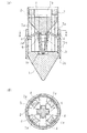
図1は、本考案に係る鋼管杭の先端拡張構造の実施例を示す図面で、(A)はその縦断面図であり、(B)は(A)のA−A矢視平面図である。図示するように、本考案に係る鋼管杭の先端拡張構造は、先端に円錐若しくは角錐状の無垢の尖頭部材1を付けた鋼管2の先端外径部に、先端に切刃が形成された筒体3を嵌着し、該筒体を嵌着した鋼管2内に、V字立上がり角度で立上がらせて斜め下方向放射状に複数の爪刃4,4,・・・を形成した拡張部材5圧入部材6が内蔵してあり、拡張部材5のV字立上がり角度Tを圧入部材6の圧入で開拡することにより、図2に示すように前記複数の爪刃4,4,・・・を筒体3の外へ斜め下方向放射状に拡張させる構造になっている。
FIG. 1 is a drawing showing an embodiment of a tip extension structure for a steel pipe pile according to the present invention, wherein (A) is a longitudinal sectional view thereof, and (B) is a plan view taken along line AA of (A). . As shown in the figure, the steel pipe pile tip extension structure according to the present invention has a cutting edge formed at the tip outer diameter portion of a
鋼管2の先端に付けた尖頭部材1は、鋼管2が丸鋼管の場合は、円錐状に先を尖らせ、鋼管2が角鋼管の場は角錐状に先を尖らせて鋼管2の先端に溶接等で付けてあり、その先端外径部に筒体3が嵌着されて溶接等で固着されている。尖頭部材1の背面には拡張部材5のV字立上がり部の下端を中心部で支持するための凹穴1aが設けられ、鋼管2と筒体3には拡張部材5の爪刃4,・・・が筒体3の外へ斜め下方向放射状に突き出して拡張するための窓口3aが設けてあり、筒体3の先端には切刃3bを設けて、位置ずれなく安定した状態で打ち込めるようにしてある。
When the
前記尖頭部材1は、比較的に硬い鋼材を使用して無垢に加工すると共に、先端の尖り部は丸みをつけて形成することにより潰れを防止し、筒体3も比較的硬い鋼管等により、先端に尖りエッジの切刃3bを形成するのが望ましく、拡張部材5は、折れにくく靱性のある鋼材で加工して形成されるのが望ましい。
The pointed member 1 is processed innocently using a relatively hard steel material, and the tip end is rounded to prevent crushing, and the
前記拡張部材5は、図3に示すような形状を呈し、爪刃4,4,・・・は、本実施例では、4方向の斜め下方向放射状に等分に割り出されて形成されたものであるが、これに限定されるものではない。おおむね3〜8方向の斜め下方向放射状に割り出されたものが好適に使用される。
The
圧入部入部材6は、前記放射状に割り出された複数の爪刃4,4,・・・の位置に合わせて形成された楔状の圧入部材であり、例えば本実施例のように複数の爪刃4,4,・・・が4方向に等分に割り出されて放射状に形成された拡張部材5(図3図示)を開拡して拡張させる圧入部材6は、図4に示すような十字状に割り出された楔状6a,6a,・・・を有する形状となる。
The press-fitting
前記拡張部材5の爪刃と爪刃の間、及び前記圧入部材6の楔部と楔部の間の間隙部には、脚7a,7a,・・・により脚立てされた打込み部材7が嵌入され、前記尖頭部材1の背面を打撃して尖頭部材1を打ち込むことにより、筒体3及び鋼管2が打ち込まれるようになっている。打込み部材7は、図5に示すような脚7a,7a,・・・を有し、内径穴7bを有する形状であり、内径穴7bにモンケン錘等の先端部を小径にして通し、圧入部材6に打撃を加えて押圧し、拡張部材5を開拡して、爪刃4,4,・・・を斜め下方向放射状に拡張させる。
なお、前記圧入部材6は、前記モンケン錘等により打撃する以外に砕石等を鋼管2内に挿填し、該挿填された砕石等に上方から油圧ジャッキ等で加圧して圧入部材6を押圧し、拡張部材を開拡して爪刃4,4,・・・を放射状に拡張させるやり方も行われる。この場合、前記打込み部材7は鋼管2内から取り外しておく必要がある。
.. Are inserted between the claw blades of the
The press-fitting
図6は、モンケンウィンチ8により、ワイヤー9で吊り下げられた棒状のモンケン錘10を鋼管内に落下させて、定尺に切断された鋼管を継ぎ足しながら打ち込む鋼管杭の打込み例であり、図7は所定の位置まで打ち込んだ鋼管杭の先端拡張例である。
FIG. 6 shows an example of driving a steel pipe pile in which a rod-shaped
図6において、ワイヤー9で吊り下げられたモンケン錘10を落下させると、打込み部材7の上端面が打撃され、打込み部材7の脚7a,7a,・・・で尖頭部材1の背面が打撃されて尖頭部材1が地中に打ち込まれると共に、筒体3の切刃3bが打ち込まれて鋼管2が下方へ下がって行く。筒体3の切刃3bが打ち込まれることにより位置ずれが防止され、真直ぐに安定した打ち込みができる。
In FIG. 6, when the
打ち込まれて下方へ下がった鋼管の上端に同径の鋼管2Aを溶接2a,2a,・・・で継ぎ足しながら、繰返しモンケン錘10を落下させて所定の深さまで打ち込む、継ぎ足す鋼管2Aは、おおむね1〜3m程度に切断された定尺材であり、モンケンウィンチ等で吊り下げたモンケン錘10の落下による打込みの場合、2〜3m程度の長い定尺材を使用するのが良い。
While the
前記図6に示すようにして所定の深さまで打ち込んだ後、図7に示すように、モンケン錘10の先端に、先端部材10aを取付け、該先端部材の打撃径部が前記打込み部材7の内径穴7bを通過するように小径にして圧入部材6の上面に打撃を加えることにより押圧し、拡張部材5の爪刃4,4,・・・が筒体3の外へ斜め下方向放射状に拡張される。
圧入部材6の上面に打撃を加えて押圧することにより沈下する場合は、鋼管の上端をサポートして行う。
After driving to a predetermined depth as shown in FIG. 6, a
When the upper surface of the press-fitting
前記拡張部材5の爪刃4,4,・・・が拡張した状態で、ワイヤー9で吊り下げられたモンケン錘10及び先端部材10aをモンケンウィンチ等で巻き上げて取り出す。
圧入部材6と打込み部材7は、そのまま鋼管2内に内蔵しても良いが、図8に示すように、モンケン錘10の先端に取付けた先端部材10aに磁石10bを取付けて、圧入部材6の上面を吸着し、モンケン錘10を引き上げることにより、打込み部材7の頭部下面が、圧入部材6の上面外周部に掛かって、圧入部材6と打込み部材7を同時に引き上げて取り出すこともできる。
In the state where the
The press-fitting
上記のようにして、拡張部材5の爪刃4,4,・・・が筒体3の外へ斜め下方向放射状に拡張された状態で鋼管内にコンクリートを流し、窓口3a,3aから筒体の外へ流して爪刃4,4,・・・をコンクリートで固めることにより、軟弱地盤等の場合など強固な支持が得られる。鋼管2A,・・・の上端は、建物や土木構築物等の基礎下面にサポート支柱(図示せず)等を介して固定する。
As described above, the concrete is poured into the steel pipe in a state where the
図9は、建物等の基礎下面に油圧ジャッキを設置して打ち込む場合の鋼管杭の打込み例であり、図10は、油圧ジャッキで所定の位置まで打ち込んだ鋼管杭の先端拡張例である。
図9に示すように、建物等の基礎11の下面に油圧ジャッキ12を設置し、油圧ジャッキ12のプッシュロッド端に取付けられた加圧プレート13で、継ぎ足した鋼管2Aの上端を加圧しながら打ち込む、継ぎ足す鋼管2Aは、鋼管2と同径で前記施工例1の場合と較べて比較的に短い方が望ましく、おおむね1〜1.5m程度の定尺材とするのが良い。
FIG. 9 is an example of driving a steel pipe pile when a hydraulic jack is installed and driven on the lower surface of a foundation such as a building, and FIG. 10 is an example of a tip extension of the steel pipe pile driven to a predetermined position with a hydraulic jack.
As shown in FIG. 9, a
前記図9のようにして所定の深さまで打ち込んだ後、図10に示すように鋼管内に砕石14,・・・を挿填して、継ぎ足して打ち込んだ鋼管2Aの上端をサポート支柱枠体15で支持して基礎11の下面に固定した状態で、油圧ジャッキ12のプッシュロッド端に取付けられた加圧プレート13aにより、挿填された砕石14の上端部を加圧することにより圧入部材6を押圧し、拡張部材5の爪刃4,4,・・・を筒体3の外へ斜め下方向放射状に拡張させる。
After driving into a predetermined depth as shown in FIG. 9, the crushed stones 14,... Are inserted into the steel pipe as shown in FIG. The press-fitting
以上のように施工されることにより、深く真直ぐに安定した鋼管杭の打ち込みが可能であると共に、任意の深さ位置における鋼管杭の先端拡張施工が可能となる By being constructed as described above, it is possible to drive steel pipe piles that are deep and straight and stable, and it is possible to extend the tip of steel pipe piles at any depth position.
1 尖頭部材
1a 凹穴
2,2A 鋼管
3 筒体
3a 窓口
3b 切刃
4 爪刃
5 拡張部材
6 圧入部材
6a 楔部
7 打込み部材
7a 脚
7b 内径穴
8 モンケンウィンチ
9 ワイヤー
10 モンケン錘
10a 先端部材
10b 磁石
11 基礎
12 油圧ジャッキ
13,13a 加圧プレート
14 砕石
15 サポート支柱枠体
DESCRIPTION OF SYMBOLS 1
Claims (3)
Priority Applications (1)
| Application Number | Priority Date | Filing Date | Title |
|---|---|---|---|
| JP2007005414U JP3135734U (en) | 2007-07-13 | 2007-07-13 | Steel pipe pile tip extension structure |
Applications Claiming Priority (1)
| Application Number | Priority Date | Filing Date | Title |
|---|---|---|---|
| JP2007005414U JP3135734U (en) | 2007-07-13 | 2007-07-13 | Steel pipe pile tip extension structure |
Publications (2)
| Publication Number | Publication Date |
|---|---|
| JP3135734U true JP3135734U (en) | 2007-09-27 |
| JP3135734U7 JP3135734U7 (en) | 2010-07-08 |
Family
ID=43286215
Family Applications (1)
| Application Number | Title | Priority Date | Filing Date |
|---|---|---|---|
| JP2007005414U Expired - Lifetime JP3135734U (en) | 2007-07-13 | 2007-07-13 | Steel pipe pile tip extension structure |
Country Status (1)
| Country | Link |
|---|---|
| JP (1) | JP3135734U (en) |
Cited By (2)
| Publication number | Priority date | Publication date | Assignee | Title |
|---|---|---|---|---|
| JP2009019448A (en) * | 2007-07-13 | 2009-01-29 | Eto Construction Industry Co Ltd | Tip widening structure of steel pipe pile, and tip widening method of steel pipe pile |
| CN106759302A (en) * | 2017-01-17 | 2017-05-31 | 上海智富建设工程有限公司 | One kind expansion uplift pile and its construction machinery and construction technology |
-
2007
- 2007-07-13 JP JP2007005414U patent/JP3135734U/en not_active Expired - Lifetime
Cited By (3)
| Publication number | Priority date | Publication date | Assignee | Title |
|---|---|---|---|---|
| JP2009019448A (en) * | 2007-07-13 | 2009-01-29 | Eto Construction Industry Co Ltd | Tip widening structure of steel pipe pile, and tip widening method of steel pipe pile |
| CN106759302A (en) * | 2017-01-17 | 2017-05-31 | 上海智富建设工程有限公司 | One kind expansion uplift pile and its construction machinery and construction technology |
| CN106759302B (en) * | 2017-01-17 | 2023-07-11 | 上海智富建设工程有限公司 | Expansion anti-floating pile, construction machine and construction process thereof |
Similar Documents
| Publication | Publication Date | Title |
|---|---|---|
| JP5067931B2 (en) | Steel pipe pile tip extension structure and steel pipe pile tip extension construction method | |
| KR100780088B1 (en) | Internal fixer for anchor having releasable tensioning steel wire | |
| EP2141286A1 (en) | Spiral steel pipe pile | |
| KR20130069169A (en) | Construction method for soft removable ground anchor using extension wing attached inner lower body | |
| JP4099199B2 (en) | Open-ended type ready-made pile and excavation head used therefor | |
| JP3135734U (en) | Steel pipe pile tip extension structure | |
| JP3139588U (en) | Dail pile | |
| JP6696232B2 (en) | Construction method of rotary press-in steel pipe pile | |
| JP6954811B2 (en) | Anchor pile | |
| KR101714610B1 (en) | Steel pipe pile construction method of sacrificial steel pipe casing partial pullout | |
| JP2007247308A (en) | Pulling-out bearing strength reinforcing for pile group comprised of inclined piles and structure constructed according to the same | |
| KR101623377B1 (en) | Reinforcing structure for pipe head | |
| JP4366597B2 (en) | Cutting and removing existing piles | |
| KR20140067787A (en) | Removable tendon cable type anchor | |
| US6641333B2 (en) | Method of forming enlarged pile heads | |
| JP2016151120A (en) | Penetration pile and method for penetrating penetration pile | |
| RU83780U1 (en) | ITS DRIVING AND DEVICE FOR ITS DIVING | |
| KR101991262B1 (en) | intensively expandable anchor apparatus with expandable wings | |
| JP5894421B2 (en) | Composite pile and composite pile construction method | |
| KR101398910B1 (en) | Extended pile | |
| KR102485680B1 (en) | Complex underground anchor with removal function | |
| KR20190032173A (en) | Rotational penetration pile unit | |
| KR101618801B1 (en) | Driven steel pile and construction method thereof | |
| GB2426777A (en) | A pile sleeve | |
| JP4049373B2 (en) | Pile placing method, pile supporting method, and plug member used in these methods |
Legal Events
| Date | Code | Title | Description |
|---|---|---|---|
| R150 | Certificate of patent or registration of utility model |
Free format text: JAPANESE INTERMEDIATE CODE: R150 |
|
| FPAY | Renewal fee payment (event date is renewal date of database) |
Free format text: PAYMENT UNTIL: 20100905 Year of fee payment: 3 |
|
| A623 | Registrability report |
Free format text: JAPANESE INTERMEDIATE CODE: A623 Effective date: 20100202 |
|
| FPAY | Renewal fee payment (event date is renewal date of database) |
Free format text: PAYMENT UNTIL: 20100905 Year of fee payment: 3 |
|
| FPAY | Renewal fee payment (event date is renewal date of database) |
Free format text: PAYMENT UNTIL: 20100905 Year of fee payment: 3 |
|
| FPAY | Renewal fee payment (event date is renewal date of database) |
Free format text: PAYMENT UNTIL: 20130905 Year of fee payment: 6 |
|
| FPAY | Renewal fee payment (event date is renewal date of database) |
Free format text: PAYMENT UNTIL: 20130905 Year of fee payment: 6 |
|
| R230 | Written correction (deletion of claims) |
Free format text: JAPANESE INTERMEDIATE CODE: R230 |
|
| R250 | Receipt of annual fees |
Free format text: JAPANESE INTERMEDIATE CODE: R250 |
|
| EXPY | Cancellation because of completion of term |