JP3134635U - Pile connection jig - Google Patents
Pile connection jig Download PDFInfo
- Publication number
- JP3134635U JP3134635U JP2007003339U JP2007003339U JP3134635U JP 3134635 U JP3134635 U JP 3134635U JP 2007003339 U JP2007003339 U JP 2007003339U JP 2007003339 U JP2007003339 U JP 2007003339U JP 3134635 U JP3134635 U JP 3134635U
- Authority
- JP
- Japan
- Prior art keywords
- pile
- piles
- jig
- main body
- connection jig
- Prior art date
- Legal status (The legal status is an assumption and is not a legal conclusion. Google has not performed a legal analysis and makes no representation as to the accuracy of the status listed.)
- Expired - Lifetime
Links
Images

Landscapes
- Piles And Underground Anchors (AREA)
Abstract
【課題】 本考案は、杭の接続作業を簡易かつ確実に行うことができる杭接続冶具を提供することを目的とする。
【解決手段】 本考案によれば、長尺管状の杭21,22を互いに接続するための杭接続冶具1であって、前記杭21、22内に収まる外径に形成された管形状の杭本体11の外周に、前記杭21、22の端部を係止する鍔部12を備えている。杭21、22は、杭接続治部1によって位置決めされ、かつ鍔部12を含む凹部において溶接される。
【選択図】 図3PROBLEM TO BE SOLVED: To provide a pile connecting jig capable of easily and surely connecting a pile.
According to the present invention, a pile connection jig 1 for connecting long tubular piles 21 and 22 to each other, and a pipe-shaped pile formed to have an outer diameter that fits in the piles 21 and 22. On the outer periphery of the main body 11, a flange portion 12 that locks the ends of the piles 21 and 22 is provided. The piles 21 and 22 are positioned by the pile connection treatment part 1 and are welded in the concave part including the flange part 12.
[Selection] Figure 3
Description
本考案は、家屋、ビル等の建造物を地上に建設する際に、地中に打ち込まれる杭同士を接続するための杭接続冶具(ジョイント)に関する。特に、作業現場において作業効率を向上できる杭接続冶具に関する。 The present invention relates to a pile connection jig (joint) for connecting piles driven into the ground when a building such as a house or a building is built on the ground. In particular, the present invention relates to a pile connecting jig capable of improving work efficiency at a work site.
建造物を地上に建設する際には、基礎を安定に形成してから組立て作業を開始することが必要である。しかし、例えば山の斜面にある土地や、以前は沼地或いは田畑であった土地等に、建造物を建設することが必要となる場合もある。このような土地は一般に地盤が脆弱である。このような土地を地均ししただけで建造物を建てると、後に地盤沈下が発生して建造物が傾く、外壁にヒビ割れが発生する等の問題が発生する。
そこで、従来から、比較的小さな建造物である住宅の建設をする場合でも、地盤が脆弱であると判断した場合には、適宜、杭を地中に打込んで基礎固めが行われている。住宅等の比較的小さな建造物の建設にあたり、地盤補強のため一般的に行われる杭打ちでは、直径100〜400mm程度の鋼製の管材が杭として地中に打込まれる。
When building a building on the ground, it is necessary to start assembling work after a stable foundation is formed. However, it may be necessary to construct a building on, for example, a land on a mountain slope or a land that was previously a swamp or a field. Such land is generally vulnerable to ground. If a building is built simply by leveling such land, problems such as ground subsidence will occur later, the building will tilt, and cracks will occur on the outer wall.
Therefore, conventionally, even when constructing a house, which is a relatively small building, if it is determined that the ground is weak, the piles are appropriately driven into the ground to solidify the foundation. In the construction of a relatively small structure such as a house, in a pile driving generally performed for ground reinforcement, a steel pipe having a diameter of about 100 to 400 mm is driven into the ground as a pile.
従来の杭打ち作業では、一つの建設地に複数の杭を打込むことが必要であり、その各々箇所で、4m〜30m程度の長さの杭が地中に打込まれる。現場に持込まれるのは通常1本当たり10m以下の杭を打込む能力を有する杭打ち機である。
よって、例えば1本1.5mから10mを越える長さの杭を打込むことが必要となったときには、先に打込んだ杭の後端部(垂直方向で上端)に他の杭の前端部(垂直方向で下端)を接続(溶接)して必要な長さを確保するようにしている。
In conventional pile driving work, it is necessary to drive a plurality of piles into one construction site, and a pile having a length of about 4 m to 30 m is driven into the ground at each location. What is usually brought to the site is a pile driver that has the ability to drive piles of 10 m or less per piece.
Therefore, for example, when it becomes necessary to drive a pile having a length exceeding 1.5 m to 10 m, for example, the front end portion of another pile is placed on the rear end portion (upper end in the vertical direction) of the pile driven first. (The lower end in the vertical direction) is connected (welded) to ensure the required length.
実際の杭打ち現場では、1本目の杭を打込んで地上に残る長さが所定となったときに打込み作業を中断する。そして、2本目の杭を1本目の杭の上に吊り上げて、1本目の杭の後端と2本目の杭の前端とを位置合わせしながら、溶接して両者を一体化させる。その後に、打込み作業を再開して所望長さの杭を打込むようにしている。
しかしながら、前述したように杭は、直径100〜400mm程度で、長さが1本10mもある鋼管であるため、相当な重量である。これを吊り下げた状態で、下の杭との位置合わせをしながら溶接するので、複数人が協力して作業を行うことが必要となる。
In an actual pile driving site, the driving operation is interrupted when the first pile is driven and the length remaining on the ground becomes a predetermined length. Then, the second pile is lifted on the first pile, and the two ends are welded together while aligning the rear end of the first pile and the front end of the second pile. After that, the driving operation is resumed and a pile having a desired length is driven.
However, as described above, since the pile is a steel pipe having a diameter of about 100 to 400 mm and a length of 10 m, the weight is considerable. Since it is welded while being aligned with the lower pile in a state where it is suspended, it is necessary for a plurality of people to work together.
ところが、上記杭の切り口端部は真っ直ぐ横に切断された状態にあるので、端部同士を突き合わせても動き易く、位置決めしてもズレが生じ易い。よって、位置決めして、溶接するという作業が極めて困難となっている。また、溶接が完了するまでその位置決め状態を保持することが必要であるので、上側の2本目の杭が動かないように作業者が支え続けなければいけない。
さらには、横切断されている鋼管の端部を突き合わせた状態で、その外周を溶接することになるため、管の内側まで十分に溶かして溶接を行うことが困難であり、溶接強度を十分に確保できないという問題もある。
However, since the cut end portion of the pile is in a state of being cut straight sideways, it is easy to move even if the end portions are brought into contact with each other, and deviation is likely to occur even if positioning is performed. Therefore, the operations of positioning and welding are extremely difficult. Moreover, since it is necessary to hold | maintain the positioning state until welding is completed, an operator must continue supporting so that an upper 2nd pile may not move.
Furthermore, since the outer periphery of the steel pipe that has been cut transversely is welded, the outer periphery of the pipe is welded. There is also a problem that it cannot be secured.
以上のように、従来の杭打ちにおける杭の接続作業は非常に煩瑣であり、非効率であった。また、仮に杭同士を接続できたとしても、その位置合わせや溶接が精度よく実行されていなければ、接続作業のやり直し等の原因ともなり、打込み作業がさらに遅れることにもなった。
したがって、本考案の主な目的は、杭の接続作業を簡易かつ確実に行うことができる杭接続冶具およびそれを用いた接続方法を提供することである。
As mentioned above, the connection work of the pile in the conventional pile driving was very troublesome and inefficient. Even if the piles can be connected to each other, if the positioning and welding are not performed accurately, the connection work may be re-executed and the driving work will be further delayed.
Accordingly, a main object of the present invention is to provide a pile connecting jig and a connecting method using the same, which can easily and reliably perform a pile connecting operation.
上記目的は請求項1に記載の如く、長尺管状の杭を互いに接続するための冶具であって、
前記杭内に収まる外径に形成された管形状の本体外周に、前記杭の端部に係止する鍔部を備えている杭接続冶具により達成される。
請求項1記載の考案によれば、一方の杭内に本体を嵌め込み、さらに他方の杭も同本体を収納するように嵌め込むことで、鍔部の前後に2つの杭を位置決めできる。よって、簡易に2つの杭を位置決めすることができる。しかも、従来のように平坦な2つの端部を突き合わせるのではなく、大きな管(杭)を小さな管(杭接続冶具の本体)を収納するように嵌め込むので、一度位置決めした2つの杭は位置ずれを生じない。
このような状態で接続作業を行うことができるので、作業効率が飛躍的に向上する。
The object is a jig for connecting long tubular piles to each other as described in
This is achieved by a pile connecting jig provided with a collar portion that engages with an end portion of the pile on the outer periphery of a tubular shape formed in an outer diameter that fits in the pile.
According to the first aspect of the present invention, the two piles can be positioned before and after the buttock by fitting the main body into one pile and further fitting the other pile so as to accommodate the main body. Therefore, two piles can be positioned easily. Moreover, instead of abutting two flat ends as in the past, a large pipe (pile) is fitted to accommodate a small pipe (main body of the pile connection jig), so the two piles once positioned are Misalignment does not occur.
Since connection work can be performed in such a state, work efficiency is dramatically improved.
なお、前記鍔部は、前記本体外周に連続するリング状に、或いは前記本体外周に不連続なリング状に形成してもよい。鍔部は少なくとも杭を係止させておくことができればよいので、完全な環状(リング状)である必要はなく、実質的に杭の端部を止めることができればよい。よって、不連続な突起がリング状に配置された状態でもよい。
また、前記鍔部は、前記本体を外周に打ち出して一体に形成してもよいし、鍔部用に別体の金属等の部材を溶接等によって付加してもよい。別体とするときには、本体と同じ部材を採用することが望ましい。さらに、鍔部は、スリーブ状の鋼管を削り出すことによって形成することもできる。この場合、ある程度肉厚のスリーブを用意し、鍔部を残すようにその他の部分を削り出し、鍔部を形成する。
また、前記鍔部の半径方向での厚みが、前記杭の肉厚よりも薄く設定されていると、溶接棒等による溶接材との接触面積が増加するのでより確実に杭接続冶具と杭、或いは杭同士を接続することができる。
また、本杭接続冶具は、前記杭と同質の金属製材料で形成されていることが望ましい。杭と同質の材料とすることで溶接等により杭と冶具をより確実に接続できる。すなわち、杭が鋼材である場合には鋼材、アルミニウム材である場合にはアルミニウム材とするのが望ましい。
The flange portion may be formed in a ring shape that is continuous with the outer periphery of the main body or a discontinuous ring shape on the outer periphery of the main body. Since it is sufficient that the heel portion can hold at least the pile, it is not necessary to have a complete ring shape (ring shape), and it is only necessary to substantially stop the end portion of the pile. Therefore, the discontinuous protrusion may be arranged in a ring shape.
Moreover, the said collar part may drive out the said main body to the outer periphery, and may form it integrally, and members, such as another metal for a collar part, may be added by welding. When using a separate body, it is desirable to employ the same member as the main body. Further, the flange portion can be formed by cutting out a sleeve-shaped steel pipe. In this case, a sleeve having a certain thickness is prepared, and other parts are cut out so as to leave the collar part, thereby forming the collar part.
In addition, when the thickness of the flange portion in the radial direction is set to be thinner than the thickness of the pile, the contact area with the welding material such as a welding rod increases, so the pile connection jig and the pile are more reliably attached. Or piles can be connected.
Moreover, it is desirable that the present pile connection jig is formed of a metal material having the same quality as the pile. By using the same material as the pile, the pile and jig can be more reliably connected by welding or the like. That is, it is desirable to use a steel material when the pile is a steel material, and an aluminum material when the pile is an aluminum material.
さらには、前記鍔部の前記杭の軸方向での厚みは、前記杭との溶接に用いる溶接材の幅より広くなるように設定されていることが望ましい。
このように設計しておくとことで、溶接材を杭間に挿入できるので溶接により十分に肉付けできるので、より確実に杭と本杭接続冶具とを接続できる。
そして、前述した杭接続冶具が端部に接続されている杭を予め準備して、この杭接続冶具に他の杭を接続するようにしてもよい。
さらに、本杭接続冶具が色々な杭の接続に有用である。よって、杭が短いような場合には、本杭接続冶具を用いて予め杭を接続して現場に持込むようにしてもよい。
Furthermore, it is desirable that the thickness of the flange portion in the axial direction of the pile is set to be wider than the width of the welding material used for welding with the pile.
By designing in this way, the welding material can be inserted between the piles, so that the welding can be sufficiently performed, so that the pile and the pile connecting jig can be more reliably connected.
And the pile in which the pile connection jig mentioned above is connected to the edge part may be prepared beforehand, and you may make it connect another pile to this pile connection jig.
Furthermore, this pile connection jig is useful for connecting various piles. Therefore, when a pile is short, you may make it connect a pile beforehand using this pile connection jig and bring it into the field.
以上、詳述したところから明らかなように、本考案によれば、杭同士を簡易かつ確実に位置決めしながら接続できるので、作業効率を向上させることができる。また、杭接続冶具の本体に設ける鍔部の形状(外表面から突出する量)を接続する杭の肉厚よりも小さくすることで、溶接材との接触面積が増加するのでより確実に杭接続冶具と杭、或いは杭同士を接続することができる。
さらに、杭接続冶具の本体に設ける鍔部の形状を杭の軸方向での厚みを、杭の溶接に用いる溶接材の幅より広くすることにより、十分に肉付けできるのでより確実に杭と本杭接続冶具とを接続できる。
As described above, as apparent from the detailed description, according to the present invention, the piles can be connected while being positioned easily and reliably, so that the work efficiency can be improved. In addition, by making the shape of the heel part (the amount protruding from the outer surface) provided on the main body of the pile connection jig smaller than the thickness of the pile to be connected, the contact area with the welding material increases, so the pile connection is more reliable. A jig and a pile, or piles can be connected.
Furthermore, by making the shape of the heel part provided in the main body of the pile connection jig wider than the width of the welding material used for welding the pile, the pile and the main pile can be surely secured. Connection jig can be connected.
以下、図面に基づいて本考案の実施例を説明する。
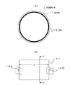
図1は、第1実施例の杭接続冶具1を示した図である。図1(A)は杭接続冶具1の平面、図1(B)は同正面を示した図である。
本杭接続冶具(ジョイント)1の杭本体11はほぼ管形状を成している。この本体11の外径Dは接続しようとする長尺の杭(ここでは図示せず)の内径より僅かに小さくなるように設計されており、使用時には本体11は杭内部に収納される状態となる。しかし、杭本体11の外周には環状の鍔部12が突出した状態に形成されており、この鍔部12は杭の端部(開口端)に係止するようになっている。
すなわち、本杭接続冶具1が杭の接続に使用されるときには、本体11は杭内に収納されるが鍔部12が杭の端部に突き当たって係止するような形態に設計されている。
Embodiments of the present invention will be described below with reference to the drawings.
The
That is, when the present
本杭接続冶具1の材質は、接続しようとする杭と同質の材料を用いることが好ましい。具体的には、杭が鋼材、アルミニウム材であるときには、これらと同様の材料を採用することで、溶接により本杭接続冶具1と杭を確実に接続できる。
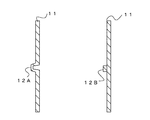
図2は、図1におけるY−Yでの断面を示した図である。図2では、杭本体11外周に形成される鍔部12を2つ例示している。
図2(A)では杭本体11をそのまま打ち出して鍔部12Aを形成している。この場合には、鍔部12Aを形成するための材料を準備することなく本杭接続冶具1を形成できる。また、鍔部12Aが杭本体11の一部であるので、溶接等を行うことなく、本体11の外周上に鍔部12Aを形成できる。
図2(B)は、杭本体11の外周に別体のリング状の材料を溶接等で付加して鍔部12Bとした場合について示している。この場合は、打出しをせずに本体11の外周上により簡易に鍔部12Bを形成できる。図2(A)、(B)どちらの構成で鍔部12を成してもよい。
As the material of the
FIG. 2 is a view showing a cross section taken along line YY in FIG. In FIG. 2, the two
In FIG. 2 (A), the pile
FIG. 2 (B) shows a case where a separate ring-shaped material is added to the outer periphery of the
さらに、図3を参照して実際に本杭接続冶具1を用いて杭同士を接続する場合について説明を加えることで、その特徴を明らかにする。
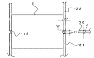
図3は、本杭接続冶具1を用いて、下側の杭21と上側の杭22とが接続される様子を示した図である。作業現場で下側の杭21を地中に打込み、例えば地上に残る長さが1m程度となったときに、本杭接続冶具1を杭21の上端部に嵌め込む。前述した所から明らかなように、接続冶具1の杭本体11は杭21内に収まるが、鍔部12は杭21の端部に係止した状態となる。このときは、鍔部12より上方にある本体11が杭21上に乗った状態となる。
続いて、上側の杭22を被せる様にして杭本体11に嵌め込めば簡単に、下側の杭21に対して杭22を位置決めできる。このとき、杭22の下端部は鍔部12に係止した状態となる。
Furthermore, the characteristic is clarified by adding description about the case where piles are actually connected using this pile connection jig |
FIG. 3 is a diagram showing a state in which the lower pile 21 and the
Subsequently, the
ところで、本実施例の鍔部12に関して好ましい条件がある。この点について説明する。鍔部12の杭本体11の外径Dによって規定される外表面から半径方向に突出する突出量Wが、杭21、22の肉厚PWより小さくなるように設定されることが望ましい。言い換えれば、杭本体11の鍔部12の外径が、杭21、22の外径よりも小さいということである。また、鍔部12の杭21、22の軸方向(図において上下方向)での厚みHは、接続する際に用いる溶接棒30の幅dより広く設定されていることが望ましい。
上記のように、鍔部12が本体1の外表面から突出する量Wが杭の肉厚PWより小さくなることで、接続部分に凹部が形成され、杭21、22の端部の一部が露出される。よって、溶接棒30を用いてアーク溶接等すると、杭の肉厚方向での溶解を確保できるのでより確実な溶接が実現できる。すなわち、端部が平坦である2つの杭を突き合わせた状態で溶接する従来の場合と比較して、凹部において溶接される面積が増加するのでより確実に溶接ができ、溶接による肉付きも多くすることができるので十分な溶接強度を確保できるようになる。また、鍔部12の軸方向での厚みHを接続する際に用いる溶接棒30の幅dより広く設定することで、溶接棒30を杭21、22の端部間に挿入できる。よって、溶接により杭21、22の端部及び鍔部12に十分肉付けできる。
By the way, there is a preferable condition for the
As described above, the amount W of the
以上のように本実施例の杭接続冶具1を用いると、一方の杭21に他方の杭22を簡単に位置決めできる。位置決めは、杭21、22の内部に杭接続冶具1の本体11が収納された状態で実現される。よって、従来のように一度、位置決め後において位置がずれないように保持するという動作が必要なくなるので、作業を簡素化して効率が向上する。また、前述したように鍔部12の寸法を所定の範囲に設定することにより、溶接による効果を確実にして、杭21、22の端部及び鍔部12に十分肉付けできる。
As described above, when the
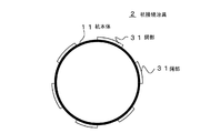
図4は、第2実施例の杭接続冶具2について示した図である。本杭接続冶具2では本体11の外周に、鍔部31が不連続なリング状に形成されている。すなわち、前述した第1実施例の鍔部12が連続したリング状に形成されていたので、この点が異なっている。
しかし、本実施例の様に鍔部を不連続に形成しても前述したと同様に2つの杭を簡易に接続することができる。なお、不連続に存在する鍔部31の数、各々の長さ、間隔等を適宜調整することで必要な強度を得ることができる。鍔部31を形成する場合も、第1実施例の場合と同様に、本体11を打ち出すことにより形成してもよいし、別体の金属等の部材を溶接等によって付加するようにしてもよい。
FIG. 4 is a view showing the
However, even if the heel portion is formed discontinuously as in this embodiment, the two piles can be easily connected as described above. In addition, required intensity | strength can be obtained by adjusting the number of the
図5は、第3の実施例に係る杭接続治部の要部断面図である。本例は、杭本体11の鍔部12Cを削り出しによって形成したものである。ある程度の肉厚のスリーブ状の鋼管を用意し、鍔部12Cに相当する部分を除きスリーブを削り出し鍔部(フランジ部)12Cを形成する。こうすると、鍔部12Cの肉厚は、上記第1および第2実施例の鍔部よりも厚くなり、鍔部12Cの強度、ひいては杭接続治具としての強度をさらに向上させることができる。削り出しされる鍔部12Cの表面からの突出量Wは、上述したように接続される杭の肉厚よりも小さくなるようにされることが望ましい。
FIG. 5: is principal part sectional drawing of the pile connection healing part which concerns on a 3rd Example. In this example, the flange 12C of the
以上、本考案の好ましい実施例について詳述したが、本考案は係る特定の実施形態に限定されるものではなく、実用新案登録請求の範囲に記載された本考案の要旨の範囲内において、種々の変形・変更が可能である。 The preferred embodiments of the present invention have been described in detail above, but the present invention is not limited to such specific embodiments, and various modifications can be made within the scope of the present invention described in the claims for utility model registration. Can be modified or changed.
上記実施例で説明した杭接続冶具1、2を予め杭21、22の一方に溶接して杭打ち現場に持込むようにしてもよい。また、杭打ち現場で用いる以外にも、本杭接続冶具が短い杭を所望の長さに接続する際に有効であることは言うまでもない。よって、本杭接続冶具で接続済みである杭を現場に持込むようにしてもよい。さらには、本杭接続冶具を2つ以上用いて、2本以上の杭を接続してもよいことは、言うまでもない。
The
1、2 杭接続冶具
11 杭接続冶具の本体
12、12A、12B、12C、31 鍔部
W 鍔部の半径方向での厚さ(本体表面からの突出量)
PW 杭の肉厚
H 鍔部の軸方向での厚さ
d 溶接棒の幅
21 下側の杭
22 上側の杭
1, 2
Thickness of PW pile H Thickness in axial direction of heel part d Width of welding rod 21
Claims (5)
平坦な端部を有し前記下側および上側の杭内に収まる一様な外径を持つ管形状の本体と、当該本体の外周に形成され前記下側および上側の杭の平坦な端部を係止する鍔部とを有し、
前記鍔部は、前記本体の外径によって規定される外表面から半径方向に突出量Wで突出する連続するリング状であり、当該突出量Wは、前記下側の杭および上側の杭のそれぞれの肉厚よりも小さく、
前記鍔部の軸方向の厚さHは、前記下側の杭および上側の杭との溶接に用いる溶接材の幅より広く、
前記本体を前記下側の杭および前記上側の杭内に挿入したとき、前記本体により前記下側の杭に対して前記上側の杭が位置決めされ、前記下側の杭の平坦な端部の一部、前記上側の杭の平坦な端部の一部、および前記鍔部の一部によって囲まれた凹部が前記下側の杭と前記上側の杭との間に形成されることを特徴とする杭接続冶具。 A jig for connecting the lower and upper piles of a long tubular shape to each other,
A tubular body having a flat end and a uniform outer diameter that fits within the lower and upper piles, and the flat ends of the lower and upper piles formed on the outer periphery of the body. Having a hook part to be locked,
The flange portion is a continuous ring shape that protrudes in the radial direction from the outer surface defined by the outer diameter of the main body, and the protrusion amount W corresponds to each of the lower pile and the upper pile. Smaller than the wall thickness of
The thickness H in the axial direction of the flange is wider than the width of the welding material used for welding with the lower pile and the upper pile,
When the main body is inserted into the lower pile and the upper pile, the upper pile is positioned with respect to the lower pile by the main body, and one flat end of the lower pile is positioned. A concave portion surrounded by a part, a part of a flat end of the upper pile, and a part of the heel part is formed between the lower pile and the upper pile. Pile connection jig.
前記鍔部は、前記本体を外周に打ち出して一体に形成されている、ことを特徴とする杭接続冶具。 In the pile connection jig according to claim 1,
The pile connecting jig, wherein the flange is integrally formed by punching the main body to the outer periphery.
前記鍔部は、前記本体とは別体の部材が外周に付加されて形成されている、ことを特徴とする杭接続冶具。 In the pile connection jig according to claim 1,
The hook connecting jig, wherein the flange is formed by adding a member separate from the main body to the outer periphery.
該杭接続冶具は、前記杭と同質の金属製材料で形成されている、ことを特徴とする杭接続冶具。 In the pile connection jig according to any one of claims 1 to 3,
The pile connection jig is formed of a metal material having the same quality as the pile.
Priority Applications (1)
| Application Number | Priority Date | Filing Date | Title |
|---|---|---|---|
| JP2007003339U JP3134635U (en) | 2007-05-10 | 2007-05-10 | Pile connection jig |
Applications Claiming Priority (1)
| Application Number | Priority Date | Filing Date | Title |
|---|---|---|---|
| JP2007003339U JP3134635U (en) | 2007-05-10 | 2007-05-10 | Pile connection jig |
Related Parent Applications (1)
| Application Number | Title | Priority Date | Filing Date |
|---|---|---|---|
| JP2002171106A Continuation JP2004019107A (en) | 2002-06-12 | 2002-06-12 | Pile connection tool and connection method using it |
Publications (1)
| Publication Number | Publication Date |
|---|---|
| JP3134635U true JP3134635U (en) | 2007-08-23 |
Family
ID=43285199
Family Applications (1)
| Application Number | Title | Priority Date | Filing Date |
|---|---|---|---|
| JP2007003339U Expired - Lifetime JP3134635U (en) | 2007-05-10 | 2007-05-10 | Pile connection jig |
Country Status (1)
| Country | Link |
|---|---|
| JP (1) | JP3134635U (en) |
-
2007
- 2007-05-10 JP JP2007003339U patent/JP3134635U/en not_active Expired - Lifetime
Similar Documents
| Publication | Publication Date | Title |
|---|---|---|
| JP3134635U (en) | Pile connection jig | |
| JP4545470B2 (en) | Joint structure of steel column and steel pipe pile | |
| JPH08284159A (en) | Pile head joint structure | |
| JP5343020B2 (en) | Beam through hole reinforcement method | |
| JP2019143346A (en) | Construction method of foundation structure | |
| JP5775750B2 (en) | Steel pipe concrete composite pile | |
| JP3062909B2 (en) | Construction method of composite underground wall using soil cement column wall | |
| JP4750414B2 (en) | Fixing jig for tack welding | |
| JP2009102818A (en) | Connection structure between pillar and steel pipe pile | |
| JP2004019107A (en) | Pile connection tool and connection method using it | |
| JP5873704B2 (en) | Joining jig and joining method | |
| JP2023102994A (en) | Tilt suppressor and method for suppressing tilt of pile | |
| JP2011252301A (en) | Pile and penetration apparatus | |
| JP4561051B2 (en) | Connection structure of steel members and steel pipe concrete | |
| JP2008303696A (en) | Guard pipe unit | |
| JP2018059294A (en) | Foundation construction method of building and foundation structure of building | |
| JP2009287338A (en) | Ground improvement method and cap member used therefor | |
| JP4781573B2 (en) | Pile head structure of foundation pile and pile head construction method of foundation pile | |
| JP2013087593A (en) | Concrete pile with outer shell steel pipe and method of manufacturing the same | |
| JP3615083B2 (en) | Steel pipe pile head connection method | |
| KR20040011722A (en) | Apparatus for connecting steel-pipe piles | |
| JP2002275888A (en) | Pile joint structure | |
| JP5054449B2 (en) | Rehabilitation method of pile foundation structure | |
| JP2001317048A (en) | Columns and column joints | |
| WO2010137294A1 (en) | Steel pipe joining structure, steel pipe joining method, and joint members |
Legal Events
| Date | Code | Title | Description |
|---|---|---|---|
| A521 | Request for written amendment filed |
Free format text: JAPANESE INTERMEDIATE CODE: A523 Effective date: 20070625 |
|
| A711 | Notification of change in applicant |
Free format text: JAPANESE INTERMEDIATE CODE: A711 Effective date: 20070625 |
|
| A521 | Request for written amendment filed |
Free format text: JAPANESE INTERMEDIATE CODE: A821 Effective date: 20070625 |
|
| R150 | Certificate of patent or registration of utility model |
Free format text: JAPANESE INTERMEDIATE CODE: R150 |
|
| FPAY | Renewal fee payment (event date is renewal date of database) |
Free format text: PAYMENT UNTIL: 20080801 Year of fee payment: 1 |
|
| EXPY | Cancellation because of completion of term |